DOI 10.1393/ncc/i2020-20054-y Colloquia: IFAE 2019
Assembly of the SM1 MicroMegas chambers for the muon
spectrometer upgrade of the ATLAS experiment at LHC
C. Arcangeletti
INFN Laboratori Nazionali di Frascati - Frascati, Italy received 8 June 2020
Summary. — MicroMegas (MICRO MEsh GAseous Structure) detectors have been chosen as new precision tracking detectors for the upgrade of the forward muon spectrometer of the ATLAS experiment, composing the New Small Wheel (NSW), for their high efficiency (better than 95%), high spatial resolution and they are able to cope with high particle fluxes. The National Institute of Nuclear Physics (INFN) has been committed to built 32 micromegas chambers for the small sector of the NSW (SM1). The SM1 modules have 2 m2 surface area and they are composed
of four gaps, each one made of a catodic plane, a metallic micromesh and an anodic plane with the readout strips to reconstruct the precision coordinate and the second coordinate stereo. The panels construction and the assembly procedure of the SM1 modules are presented.
1. – Introduction
An upgrade programme of the LHC is planned, aimed to reach peak luminosity of 5–7 times the initial design values and a final integrated luminosity of about 3000 fb−1in a dozen years after the upgrade. Due to the increase of the particle rate in the detectors the ATLAS experiment has planned several upgrades to stay operative. Then during the two long shutdown periods (2019–2020 LS2 and 2024–2026 LS3) ATLAS will undergo major upgrades: Phase I [1] and Phase II [2].
The most important upgrade project during Phase I is the new small wheel project [3], consisting of the replacement of the innermost muon station in the end-caps, the small wheels, with a completely new detectors technology, the MicroMegas detectors (MM) [4, 5], and the small Thin Gas Chamber (sTGC) detectors [6].
2. – New small wheel upgrade project and the micromegas detector
The New Small Wheel (NSW) upgrade of the ATLAS experiment consists in the replacements of all the detectors currently installed in the innermost muon station in Creative Commons Attribution 4.0 License (http://creativecommons.org/licenses/by/4.0) 1
• Ability to cope with high particle fluxes to reject fake triggers.
The NSW structure consists of 8 large sectors and 8 small sectors, with 2 modules per sector and 4 MM quadruplets. MM chambers are therefore produced in 4 different shapes: LM1, LM2, SM1, SM2 (fig. 1).
The production is distributed in institutes in different countries: Germany (SM2), France (LM1), Russia-Greece-CERN (LM2) and Italy (SM1). The INFN has been com-mitted to built 32 quadruplets.
MicroMegas chambers is an abbreviation for MICRO MEsh GASeous Structure and it is an innovative design concept for Micro-Pattern Gaseous Detectors first introduced by Charpak and Giomataris during the 1990s [4]. Large-area chambers based on the micromegas technology have been chosen as new precision tracking detectors, for the upgrade of the forward muon spectrometer of the ATLAS experiment at the Large Hadron Collider (LHC) during the second long shutdown of the LHC [5].
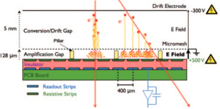
MicroMegas are gas detectors in which a 5 mm gap between two parallel electrodes is filled with a 93 : 7 Ar : CO2 gas mixture and a thin metallic micromesh is placed
between the two electrodes, held by pillars with a pitch of few millimetres and a height of about 128 μm (fig. 2). In this way two different regions are defined: a drift region defined by the drift electrode, with a −300 V voltage applied, and the grounded mesh; and an amplification region between the mesh and the anode that is done with resistive strips kept at 570 V. In the drift region the primary ionisation takes place and the low electric field (∼600 V/cm) leads the produced electrons towards the mesh. Following the field lines they enter the very thin amplification region, in which the avalanche takes place due to the very high electric field (40–50 kV/cm), with a gain of the order of 104.
Fig. 1. – The NSW subdivision in small (S) and large (L) sectors and the division of the sector readout planes into 8 anode PCBs grouped in two modules (5 PCBs + 3 PCBs).
Fig. 2. – Schematic view of the micromegas detector and the principles of operation.
Furthermore the thin amplification gap allows a fast ions evacuation, which occurs in about 100 ns, and allows MM to operate in highly irradiated environments. Finally the produced signal is then read by the readout strips capacitively coupled to the resistive ones (pitch of about 400 μm) in order to reduce the performance degradation due to discharges in the detector.
3. – SM1 module construction
A MicroMegas module for the NSW is made of four gas gap (Quadruplet ) and it consists of 5 panels: two outer drift panels, one central drift panel and two readout panels, the Eta (with vertical strip to measure the η coordinate) and the Stereo (with strip tilted at±1.5◦to allow also the measurement of the second φ coordinate).
The INFN Italian production for the SM1 chambers is summarized as shown in fig. 3 [7].
The meshes are prepared in parallel at Roma-3. The mesh lays on the stretching table and it is held with 28 clamps that is gradually moved away until a tension of∼10 N/m is reached. The drift panel is finalised in Cosenza and then at LNF, where a frame 5 mm thick is fixed on the bare drift panel to build the ionization gap and the stretched mesh is glued over this frame. The mesh tension is checked during this steps, and finally the high voltage and the gas tightness tests are performed to ensure the operation of the drift panel. Some pictures of the drift panels construction phases are shown in fig. 4 together with the planarity measurements and the mesh tension maps.
3.2. Readout panel . – The two readout panels of the SM1 modules are prepared in Pavia in the clean room using the stiff-back technique [9] (fig. 5 top, left). A readout panel has 5 PCBs for each side, and these PCBs are made of a layer of copper strip, the insulator layer and the layer of resistive strips. The assembly starts placing the first PCB skin on the granite table, precisely positioned using reference pins, and sucked on this with a vacuum pump, and the second skin is placed on the stiff-back. Then the frames and the honeycomb are glued over the first PCB skin and after the stiff-back is rotated upside-down and moved over the table to put the second skin on top of the assembled panel. As for the drift panels, the planarity of the readout panels is lower that 37 μm.
An important step of the readout panel construction is the test of the readout strips alignment. This measurement is performed with custom-made tools (based on the Rasnik system [10]) able to read the coded masks placed on the PCB external side through contact-CCDs (fig. 5 top, right). These tools perform measurement both of the mis-alignments and rotations of the strips PCB-to-PCB and of the strip alignment
Fig. 4. – Left (clockwise): the vacuum bag technique, a final drift panel and the mesh on the stretching table. Center: measurement of the thickness and planarity for a drift panel. Right: measurement of the mesh tension map.
Fig. 5. – Top, left: the stiff-back technique scheme. Top, right: contact-CCD to measure the alignment of the readout strips. Bottom: final readout panel.
layer-to-layer. The tolerance for the absolute alignment is Δη < 40 μm, instead for the relative alignment between the two sides of the panel it is Δη < 60 μm.
3.3. Cleaning procedure. – During the panels and the board production it is possible that some organic residuals remain on the surfaces, compromising the high voltage sta-bility of the chambers. A great improvement came from the development of a cleaning procedure of the panels, using specific micropolishig detergents, demineralised water and an oven to dry the panels before the assembly.
3.4. Module assembly. – At the LNF an assembly procedure of the chambers to guar-antee the alignment of the readout strips has been developed, together with a validation
Fig. 6. – Left: closure of the first gap with the panel positioned on the vertical tools. Right: the assembled quadruplet positioned on the supports ready for the validation measurements in clean room.
high voltage test is done on each gap. Figure 6 shows the closure of the first quadruplet gap and a finalised module.
4. – Conclusions
The micromegas chambers will be used for the precision tracking detectors in the New Small Wheel of ATLAS. These detectors show a very good performance in highly irradiated environment. INFN is deeply involved in the production of the SM1 modules. It consists in three drift panels and two readout ones, built and tested independently and finally assembled at LNF. Up to now 2 prototypes and 14 production chambers have been done, and the first module is already installed in the first double-wedges of the NSW together with the SM2 module.
REFERENCES
[1] ATLAS Collaboration, Letter of Intent for the Phase-I Upgrade of the ATLAS Experiment, Technical Report CERN-LHCC-2011-012. LHCC-I-020, CERN, Geneva, Nov. 2011.
[2] ATLAS Collaboration, Letter of Intent for the Phase-II Upgrade of the ATLAS Experiment, Technical Report CERN-LHCC-2012-022. LHCC-I-023, CERN, Geneva, Dec. 2012.
[3] Kawamoto T. et al., New Small Wheel Technical Design Report, CERN-LHCC-2013-006, ATLAS-TDR-020.
[4] Giomataris Y., Rebourgeard P., Robert J. P. and Charpak G., Nucl. Instrum. Methods A, 376 (1996) 29.
[5] ATLAS Muon Collaboration (Iodice M.), JINST, 10 (2015) C02026.
[6] Majewski S., Charpak G., Breskin A. and Mikenberg G., Nucl. Instrum. Methods, 217 (1983) 265.
[7] Alexopoulos T., Alviggi M., Antonelli M. et al., Nucl. Instrum Methods Phys. Res. A, 955 (2020) 162086.
[8] The Roma1 MM Group, The vacuum bag technique for the MicroMega panel construction, ATL-COM-MUON-2014-024.
[9] Iengo P. et al., PoS, TIPP2014 (2014) 058. [10] Beker M. et al., JINST, 14 (2019) P08010.