Alma Mater Studiorum – Università di Bologna
in cotutela con
Ecole Nationale Supérieure de Chimie de Montpellier
DOTTORATO DI RICERCA IN
CHIMICA
Ciclo XXIX
Settore Concorsuale di afferenza: 03/C2 Settore Scientifico disciplinare: CHIM/04
CHEMICAL-LOOP APPROACH IN BIO-ALCOHOLS
REFORMING
Presentata da: Olena Vozniuk
Coordinatore Dottorato
Relatore
Chiar.mo Prof. Aldo Roda
Prof. Fabrizio Cavani
Relatore
Prof. Francesco Di Renzo
3
Chemical-Loop Reforming
Water Splitting
Hydrogen production
Spinel oxides
Mössbauer spectroscopy
Magnetic measurements
TPR/O
in-situ XPS
in-situ DRIFTS
5
TABLE OF CONTENTS
1. INTRODUCTION ... 24 1.1. Hydrogen applications ... 24 1.1.1. Fuel cells ... 25 1.2. Hydrogen production ... 27 1.2.1. Common feedstocks ... 271.2.2. Common processes for H2 production ... 27
1.2.3. Hydrogen via Reforming Processes ... 28
1.2.4. Hydrogen via Chemical-Loop (CL) processes ... 32
1.3. Spinel oxides: AB2O4 ... 38
Structure of AB2O4 oxides ... 39
1.4. Aim of the research project ... 41
2. CHARACTERIZATION TECHNIQUES AND SET-UP OF LABORATORY PLANT ... 43
2.1. X-ray diffraction (XRD) ... 43
2.2. Raman Spectroscopy ... 45
2.3. Mössbauer Spectroscopy ... 45
2.4. Surface area measurements... 47
2.5. SEM/TEM-EDX analysis ... 48
2.6. Temperature programmed reduction/oxidation (TPR1/O/R2) ... 48
2.7. Carbon content measurements (CHNS) ... 49
2.8. Magnetic measurements ... 49
2.9. In-situ X-ray Photoelectron Spectroscopy (XPS) experiments ... 49
2.10. Diffuse-Reflectance Infrared FT spectroscopy (DRIFTS) experiments ... 51
2.11. Reactivity experiments: Chemical-Loop Reforming (CLR) process ... 55
3. MATERIALS PREPARATION ... 61
4. RESULTS AND DISCUSSION, PART I: TYPE I SPINELS (MFe2O4) ... 63
Bulk characterization of fresh materials ... 63
4.1. Energy dispersive spectroscopy (EDX) ... 63
4.2. XRD and N2 adsorption ... 64
4.3. Raman Spectroscopy ... 66
4.4. Temperature programmed reduction/oxidation (TPR1/O/R2) ... 67
4.5. Ex-situ XRD study of MFe2O4 ferrites ... 79
4.6. Ex-situ Mössbauer study ... 89
6
4.8. Characterization of cycled looping materials: 3 steps CLR - 1 complete cycle (20 min red/20
min re-ox/30 min air) ... 115
4.9. 2 steps CLR vs 3 steps CLR: cycling of looping materials (3 cycles∙20 min) ... 118
4.10. Conclusions on the study of MFe2O4 ferrospinels ... 124
5. RESULTS AND DISCUSSION, PART II: TYPE II SPINELS (M0.6Fe2.4Oy) ... 126
5.1. Energy dispersive spectroscopy (EDX) ... 126
5.2. XRD and N2 adsorption ... 127
5.3. Raman Spectroscopy ... 128
5.4. Temperature programmed reduction (TPR) ... 131
5.5. Ferrospinels TYPE II: study of Co0.6-xMnxFe2.4Oy system ... 136
5.6. Surface characterization: in-situ DRIFTS experiments ... 137
5.7. Surface characterization: in-situ XPS study ... 142
5.8. Reactivity tests: Co0.6-xMnxFe2.4Oy system ... 150
5.9. Conclusions on the study of Co0.6-xMnxFe2.4Oy ferrospinels ... 160
5.10. Ferrospinels TYPE II: study of Cu0.6-xMnxFe2.4Oy system ... 161
5.11. Mössbauer spectroscopy ... 162
5.12. Magnetic measurements... 166
5.13. Temperature programmed reduction (TPR) study ... 170
5.14. Surface characterization: in-situ DRIFTS experiments ... 173
5.15. Ex-situ XRD study of the reduced samples ... 176
5.16. Mössbauer study of the reduced samples ... 181
5.17. Reactivity tests: Cu0.6-xMnxFe2.4Oy system ... 185
5.18. Conclusions on the study of Cu0.6-xMnxFe2.4Oy system ... 194
6. CHEMICAL-LOOP REFORMING: REACTIVITY TESTS M0.6Fe2.4Oy ... 197
6.1. 1st step: reduction with ethanol at T-450oC ... 198
6.2. Ex-situ XRD study over cycled materials after 4 cyc∙20 min+1 red ... 203
6.3. 2nd step: re-oxidation with water at T-450oC ... 206
6.4. Ex-situ XRD study over cycled materials after 5 cyc∙20 min ... 208
6.5. Raman spectroscopy over cycled materials ... 212
6.6. Conclusions on the study of M0.6-xFe2.4Oy ferrospinels ... 214
7. TYPE I vs. TYPE II FERROSPINELS ... 215
7.1. Conclusions: TYPE I vs. TYPE II ferrospinels ... 219
LITERATURE ... 220
ABSTRACT 7 ABSTRACT
Nowadays, hydrogen production is mainly based on the reforming of natural gas or naphtha. Less energy intensive and more sustainable processes for hydrogen production are appealing for both industry and consumer applications. Chemical-loop steam reforming is one of the possible ways to produce H2 starting from
either conventional or renewable sources. Differently from classical reforming, separation costs can be avoided by splitting the process into two alternated steps in order to detach H2 and COx streams. One of the
advantages of this technology relates to its feedstock flexibility.
This PhD project deals with an investigation of a new process, named as Chemical-Loop Reforming (CLR) process, aimed to produce “clean H2” with an inherent COx separation. The main principle of the CLR process is
that an oxygen-storage material is first reduced by an ethanol stream (T-450oC) and then re-oxidized by water (T-450oC) to produce hydrogen and to restore the original oxidation state of the looping-material. The choice of ethanol as a reducing agent has several advantages: its renewable origin together with the possibility to decompose at a relatively lower temperature with a formation of the hydrogen-rich mixture.
Different M-modified spinel-type mixed oxides: TYPE I – MFe2O4 and TYPE II – M0.6Fe2.4Oy viz. modified
ferrospinels (where M=Cu, Co, Mn, Mg, Ca and Cu/Co, Cu/Mn, Co/Mn), as potentially attractive ionic oxygen and electron carrier looping materials, were prepared via co-precipitation method and tested in terms of both redox properties and catalytic activity to generate hydrogen by oxidation with steam, after a reductive step carried out with ethanol. Particularly, the focus on the reactivity behavior of binary/ternary materials explained by their ability to form thermodynamically stable spinel oxides which allow us to re-obtain the initial spinel phase upon cycling and in turn increase a stability of the looping material itself. In addition, the research includes in-situ DRIFTS and in-situ XPS studies that allowed to extract information at a molecular level and to follow surface changes within the reduction/re-oxidation processes during ethanol chemical-loop reforming. Bulk characterizations have been done using XRD, TPR/O, TEM/SEM/EDX, Magnetic measurements and Raman/Mössbauer spectroscopic techniques. Moreover, a modification of the conventional CLR process with an addition of the 3rd regeneration step (carried out with air) was done to increase the stability of the looping material and to overcome the deactivation problems, such as: a coke deposition/accumulation and an incomplete re-oxidation of M0 during the 2nd step; the obtained results are compared to a conventional 2 steps CLR process.
RÉSUMÉ 9 RÉSUMÉ
Aujourd’hui, la production d’hydrogène est basée essentiellement sur le reformage du gaz naturel ou des essences légères. Des procédés moins énergivores et plus durables pour la production d’hydrogène sont intéressants tant pour des applications industrielles que pour des produits pour grand public. Le reformage à la vapeur par cycle redox est une des voies possibles pour produire de l’H2 à partir de sources traditionnelles
comme de sources. A différence du reformage classique, les coûts de séparation peuvent être évités en séparant le procédé en en deux étapes alternées pour isoler les débits d’H2 et COx. L’un des avantages de
cette technologie est lié à sa flexibilité envers les matières premières utilisées.
Le sujet de thèse est l’étude exploratoire d’un nouveau procédé de reformage par cycle redox (CLR : Chemical-Loop Reforming) avec séparation intrinsèque des COx, visant la production d’“H2 propre. Le principe essentiel
du procédé CLR est basé sur le cycle redox d’un matériau de stockage d’oxygène, qui est d’abord réduit par un flux d’éthanol (T-450oC) et ensuite réoxydé par de la vapeur d’eau (T-450oC) pour produire de l’hydrogène et rétablir l’état d’oxydation initial du matériau à cycle redox. Le choix de l’éthanol comme agent réducteur présente plusieurs avantages, de son origine renouvelable à sa propriété de décomposition à une température relativement basse avec la formation d’un mélange riche en hydrogène.
Les oxydes mixtes de structure spinelle (ferrospinelles modifiées) sont des matériaux potentiellement intéressants pour le cyclage redox d’ions oxygènes et porteurs d’électrons. Plusieurs de ces spinelles M-modifiée de TYPE I – MFe2O4 et TYPE II – M0.6Fe2.4Oy M-modifiée de TYPE I – MFe2O4 et TYPE II – M0.6Fe2.4Oy
avec M=Cu, Co, Mn, Mg, Ca et Cu/Co, Cu/Mn, Co/Mn) ont été préparées par une méthode de coprécipitation et elles ont été évaluées soit de par leurs propriétés redox et leur activité catalytique dans la production d’hydrogène par oxydation par la vapeur d’eau après une étape de réduction à l’éthanol. En particulier, l’attention a été portée sur la réactivité des matériaux binaires/ternaires à cause de leur propriété de former des spinelles thermodynamiquement stables, ce qui nous a permis de réobtenir la phase spinelle initiale après cyclage redox tout en augmentant la stabilité du matériau de cyclage. De plus, l’activité de recherché a inclut des études in-situ, DRIFTS et XPS, qui ont permis d’obtenir des informations au niveau moléculaire et de suivre les modifications de surface du matériau au cours des étapes de réduction et réoxydation pendant le reformage de l’éthanol par cyclage redox. Les matériaux ont été caractérisés par DRX, TPR/O, MET/MEB/EDX, mesures magnétiques et techniques spectroscopiques Raman/Mössbauer. De plus, une modification du procédé CLR conventionnel avec l’addition d’une troisième étape de régénération à l’air a permis d’augmenter la stabilité du matériau de cyclage redox et de surmonter les problèmes de désactivation, tels que le dépôt/accumulation de coke et la réoxydation incomplète de M0 pendant l’étape de réoxydation à la vapeur d’eau. Les résultats obtenus ont été comparées à un procédé CLR conventionnel à deux étapes.
RÉSUMÉ 10
OBJECTIFS DU PROJET DE RECHERCHE
Le travail de recherché présenté ici est étude sur un nouveau procédé de reformage par cyclage redox (Chemical-Loop Reforming: CLR) pour produire de l’“H2 propre” avec une séparation
intrinsèque des COx. Le principe de base du procédé CLR est le cyclage d’un matériau de stockage
d’oxygène, qui est d’abord réduit par un flux d’éthanol (T-450oC) et ensuite réoxydé par de la vapeur d’eau (T-450oC) pour produire de l’hydrogène et rétablir l’état d’oxydation initial du matériau de
cyclage (Figure 1).
Figure 1. Reformage par cyclage redox de l’éthanol sur ferrospinelles modifiées
Le choix de l’éthanol comme agent réducteur présente plusieurs:
- L’éthanol peut être obtenu à partir de biomasse, ce qui peut contribuer à développer la production d’hydrogène à partir de matières premières différentes des combustibles fossiles;
- L’éthanol est un liquide non toxique, facile à transporter et manipuler, assez stable à température ambiante, bien adapté pour des usages dans des produits pour le grand public; - L’utilisation de bioalcohol en reformage par cycle redox a jusqu’à présent attiré peu
d’attention dans la littérature;
La tâche initiale du projet a été la définition des conditions et matériaux adaptés pour l’obtention d’un procédé optimise pour la production d’un flux d’hydrogène qui ne demande aucune opération de séparation ou purification supplémentaire. Par conséquent, plusieurs oxydes mixtes de type spinelle M-modifiées (TYPE I – MFe2O4 et TYPE II – M0.6Fe2.4Oy) ont été synthétisés et testés comme
matériaux de cyclage d’ions oxygènes et porteurs d’électrons dans la génération d’hydrogène par oxydation à la vapeur d’eau après une étape de réduction à l’éthanol. Plus spécifiquement, l’attention a été portée sur la réactivité des spinelles secondaires et tertiaires , grâce à leur capacité de former des oxydes thermodynamiquement stables qui pouvaient recouvrer leur phase initiale
RÉSUMÉ 11
après un cyclage redox. La composition de ferrospinelles MFe2O4 et M0.6Fe2.4Oy a été variée avec des
ions de métaux de transition (Co, Mn, Cu ou Cu/Co, Cu/Mn, Co/Mn) et des ions de métaux alcalinoterreux: Ca, Mg. L’objectif de ces modifications des matériaux a été la recherche d’une sélectivité améliorée pour obtenir des produits valorisables au cours de la première étape de réduction et une plus grande pureté de l’hydrogène produit dans la deuxième étape de réoxydation. La deuxième tâche a été l’étude de la chimie du procédé, à travers des techniques de caractérisation in-situ et ex-situ et l’étude des propriétés des oxydes mixtes, en terme de propriétés redox, morphologiques et physico-chimiques, en incluant des études de propriétés de chimie de l’état solide des matériaux avant et après cyclage redox.
La recherche a été conduite sur les sites de trois institutions, les détails sur l’organisation du travail étant résumés dans la Figure 2.
Figure 2. Travail accompli pendant les trois années de recherché doctorale
DIFFRACTION DES RAYONS X ET ADSORPTION DE N2
La structure des ferrospinelles de TYPE I (MFe2O4) et TYPE II (M0.6Fe2.4Oy) préparées par
coprécipitation a été identifiée par les diffractogrammes de poudres reportés en Figures 3. Les diffractogrammes indiquent la formation de spinelles comme phases principals pour tous les échantillons MFe2O4 et M0.6Fe2.4Oy. Un clair élargissement des raies de diffraction a été observé
préférentiellement pour les ferrospinelles des deux types contenant du manganèse, comme MnFe2O4, Cu0.5Mn0.5Fe2O4, Co0.5Mn0.5Fe2O4 and Mn0.6Fe2.4Oy, Co0.3Mn0.3Fe2.4Oy, Cu0.3Mn0.3Fe2.4Oy,
RÉSUMÉ 12
Co0.54Mn0.06Fe2.4Oy. Cet effet a été attribué à une diminution de la taille des particules ou à une
baisse de cristallinité. Dans le Tableau 1 sont indiquées les valeurs de surface spécifique (SSA), taille des cristallites (calculée par l’équation de Scherrer ou la méthode de Williamson-hall) et taille des particules des échantillons calcinés à 450oC pour 8 h.
Figure 3. Diffractogrammes de poudres des spinelles MFe2O4 (en haut) et M0.6Fe2.4Oy (en bas) calcinées à 450 o
RÉSUMÉ 13
Tableau 1. Surface spécifique (SSA) et taille des cristallites/particules des ferrites MFe2O4 and M0.6Fe2.4Oy Sample name SSA fresh,
m2/g Crystallite size (Scherrer eq.) fresh, nm Particle size (dBET), nm TYPE I: MFe2O4 CuFe2O4 60 6.9 18.3 Cu0.5Co0.5Fe2O4 67 10.4 16.5 CoFe2O4 69 12 16.2 Co0.5Mn0.5Fe2O4 141 3.5 8 Cu0.5Mn0.5Fe2O4 112 - 10 MnFe2O4 165 - 6.9 TYPE II: M0.6Fe2.4Oy Co0.6Fe2.4Oy 71 7 16 Co0.54Mn0.06Fe2.4Oy 88 4 13 Co0.3Mn0.3Fe2.4Oy 138 3 8 Mn0.6Fe2.4Oy 157 - 7 Cu0.3Mn0.3Fe2.4Oy 131 - 9 Cu0.6Fe2.4Oy 72 5 15
Toutes les ferrites contenant du Mn présentent une surface spécifique plus élevée aussi après traitement thermique. Cet effet peut être attribué d’abord à la présence de plus petites particules ainsi qu’à la présence d’une phase amorphe, en bon accord avec les résultats de diffraction présentés plus haut. Une confirmation ultérieure a été obtenue par la comparaison de la taille des cristallites obtenue par exploitation de la largeur des raies de diffraction avec la taille des particules calculée à partir de la SSA à travers une supposition sur la forme des particules, assumées sphériques et non poreuses pour les besoins du calcul.
REDUCTION À TEMPÉRATURE PROGRAMMÉE (TPR)
La réduction des oxydes de fer(II,III) (Fe
3O4→FeO→Fe) dépend fortement de la présence d’autres
oxydes métalliques dans la ferrite M-modifiée résultante. Selon les résultats de DRX discutés plus haut, la phase principale obtenue au bout de la procédure de préparation est une phase spinelle de type Fe3O4 avec une formule générale MFe2O4/M0.6Fe2.4Oy. Dans les courbes TPR profiles des ferrites
RÉSUMÉ 14
M-modifiées reportées en Figure 4, on reconnaît deux étapes principales du processus de réduction : la réduction de l’oxyde de fer à fer métalliques et le processus propre de réduction de l’autre oxyde métallique incorporé à son métal. Toutefois, il est difficile de séparer les étapes de réduction puisque certaines étapes se fondent sans transition, en se superposant l’une dans l’autre. Néanmoins, les résultats obtenus et leur élaboration ultérieure, basée sur la nature des métaux additionnels (M2+), leurs potentiels de réduction et les quantités d’H
2 consommées, nous ont permis
de définir des étapes probables du processus de réduction des MFe2O4, étapes qui sont résumées
dans la Figure 5.
En considérant le profil TPR profile de CuFe2O4, le premier pic à 240oC peut être attribué à une
réduction rapide de l’oxydes de cuivre présent dans l’échantillon (CuO~21%w) à cuivre métallique
(Cu0), ce qui conduit à une fraction de consommation d’H
2 ɑ~16%. Le deuxième pic à ~ 340oC a été
attribué à la première étape de réduction de la spinelle selon le mécanisme I de Figure 5, avec la formation de phases Cu0 et Fe
3O4 (ɑ~27%). La réduction ultérieure de Fe3O4 à FeO et FeO à Fe0 se
manifeste à plus haute température jusqu’à ɑ~70%. La réduction des échantillons Cu0.5Mn0.5Fe2O4 et
Cu0.5Co0.5Fe2O4 suit le mécanisme III de Figure 5, dans lequel le premier pic à basse température
correspond à la démixtion par étapes et/ou la réduction des cations M incorporés pour former des phases M (Cu0), MO (MnO/CoO) et Fe3O4.
RÉSUMÉ 15
Figure 4. Courbes TPR de ferrites MFe2O4 (en haut) et M0.6Fe2.4Oy (en bas) avec programmation de température de 50 to 800oC suivie
d’une isotherme at 800o
RÉSUMÉ 16
Figure 5. Schéma de réduction des ferrites MFe2O4
La réduction ultérieure des ferrites Cu0.5Co0.5Fe2O4 passe par les étapes suivantes: (1) Fe3O4→FeO
(+0,77eV), (2) CoO→Co0 (-0.28 eV), (3) FeO→Fe0incom (-0.44 eV) et atteint une ɑ~65%. D’autre côté, la
deuxième phase de réduction des ferrites Cu0.5Mn0.5Fe2O4 peut être ainsi schématisée: (1)
Fe3O4→FeO, (2) FeO→Fe0incom, ce qui correspond à ɑ~65%. Il en résulte qu’il est difficile de réduire
MnO à son correspondant métallique Mn0, à cause de son potentiel de réduction très négatif (-1.18
eV),donc cette étape peut avoir lieu seulement à des températures très élevées. La réduction des échantillons CoFe2O4, Co0.5Mn0.5Fe2O4 et MnFe2O4 suit le mécanisme II de Figure 5. Dans le cas de
CoFe2O4, le premier petit pic à 400oC peut être attribué à la réduction initiale de la spinelle avec une
étape de formation de phases CoO et Fe3O4 (correspondant à ɑ~8%), tandis que dans les ferrites
contenant du manganèse (MnFe2O4 et Co0.5Mn0.5Fe2O4) cette étape commence à plus basse
température. Cependant, le degré de réduction final de CoFe2O4 (ɑ~86%) a été bien plus élevé que
celui des échantillons Co0.5Mn0.5Fe2O4 (61%) et MnFe2O4 (45%), ce qui peut être expliqué par la
formation de la phase MnO, difficile à réduire en tant que telle ou sous forme de solution solide MnxFeyO.
Les mécanismes de réduction proposés sur la base des résultats obtenus sur les ferrospinelles de TYPE I (MFe2O4), reportés en Figure 5, peuvent être appliqués aux courbes TPR des échantillons de
TYPE II (M0.6Fe2.4Oy). Un épaulement de réduction à basse température, près de ∼200◦C, qui
correspond à ~5% de la réduction totale, observé expérimentalement pour les échantillons contenant Co, Co/Mn et Mn, a été attribué à la réduction de M0.57Fe2.28O4 à M0.6Fe2.4O4, engendrée
par la présence de lacunes cationiques dans des matériaux suroxydés hautement défectif. On remarque que la présence de fer seulement sous forme de cations Fe3+ dans les échantillons initiaux
a été confirmée par expériences Mössbauer où les valeurs d’IS (δ) sont dans le domaine typique des espèces Fe3+: 0.31-0.35 mm/s, ce qui implique une suroxydation pour ces échantillons
surstoechiométriques en fer. La réduction ultérieure des échantillons Co0.6Fe2.4Oy(A),
RÉSUMÉ 17
TYPE I avec Co, Co/Mn et Mn (mécanisme II en Figure 5). Le premier petit pic à ~400oC a été attribué
à la réduction initiale de la spinelle avec formation par étapes de phases CoO et Fe3O4 (ou CoO, MnO
et Fe3O4), ce qui corresponds à un degré d’avancement de la réduction ɑ~8%, tandis que dans la
ferrite au manganèse Mn0.6Fe2.4Oy, cette étape commence à la plus basse température de ~380oC
(Mn0.6Fe2.4O4 + 0.2 H2 donne 0.6 MnO + 0.8 Fe3O4 + 0.2 H2O). De toute façon, les échantillons au
cobalt attaignent un degré de réduction significativement plus élevé (ɑ~80(A), 75(B) and 55(C)%) par
rapport à l’échantillon au manganèse (ɑ~58(D)%), ce qui a été encore une fois attribué à la formation d’une phase difficilement réductible, sous la forme de MnO ou d’un oxyde mixte MnxFeyO à
structure wustite. Dans les courbes TPR des ferrites Cu0.6Fe2.4Oy(E) et Cu0.3Mn0.3Fe2.4Oy(F), le premier
pic à ~350oC a été attribué à la première étape de réduction de la spinelle avec formation finale de
phases Cu0(E)/Cu0+MnO(F) et Fe
3O4, correspondant à ɑ~23(E)/16(F)%), suivant les mécanismes I(E)/III(F)
de Figure 5. Les étapes ultérieures de réduction Fe3O4 FeO et FeO Fe0 se déroulent à plus
haute température avec un degré de réduction global de ~52(E)/46(F)%. Comme expliqué plus haut
pour les ferrospinelles avec Co/Mn et Mn, la réduction MnO Mn0 (-1.18 eV)peut avoir lieu seulement à des températures très élevées, ce qui favorise la formation de phases difficilement réductibles MnO/MnxFeyO.
EXPÉRIENCES DE RÉACTIVITÉ SUR FERROSPINELLES TYPE I ET TYPE II
Le choix de conditions de réaction et temps de cycle a été basé sur les études précédents de Cocchi (méthanol comme agent réducteur, Tred – 300 et 420oC/Tre-ox – 420oC, matériaux de cyclage : Fe3O4,
CoFe2O4 et NiFe2O4) et Trevisanut (éthanol comme agent réducteur, Tscreen red – 400 et 450oC/Tre-ox –
450oC, matériau de cyclage: Fe3O4, CoFe2O4 et NiFe2O4). Il faut remarquer que le but essential de
l’étape de réduction était de maximiser le niveau de réduction tout en améliorant la reproductibilité des cycles redox en minimisant la désactivation du matériau de cyclage, conséquence d’une accumulation de coke. Ces résultats précédents ont suggéré comme meilleures conditions de réaction une première étape de réduction par l’éthanol à Tred-450oC et une deuxième étape de
réoxydation par la vapeur d’eau à Tre-ox-450oC. Le temps de cyclage a été choisi sur les même bases
et a été divisé en cycles longs (durée d’un cycle complet: 1 h red/1 h re-ox) et cycles courts (durée d’un
cycle complet: 20 min red/20 min re-ox ou 6 min red/6 min re-ox). La durée optimisée pour chaque étape
a été fixée à 20 minutes par cycle. Cependant, les moles globales d’H2 formées pendant la deuxième
étape ont été comparée à la même durée globale pour des cycles à rythme différent: par exemple 1h (total→60 min) = 3 cyc∙20 min (total→60 min) = 10 cyc∙6 min (total→60 min). La composi`on des
RÉSUMÉ 18
ferrospinelles M0.6Fe2.4Oy a aussi été variée en changeant les métaux de transition Co, Mn, Cu ou les
métaux alcalinoterreux Ca, Mg. L’objectif de ces modifications a été l’obtention d’une plus grande sélectivité vers des produits valorisables dans la première étape de réduction ainsi qu0une plus grande pureté del’H2 produit dans la deuxième étape de réoxydation.
Dans la Figure 6 sont résumées les valeurs intégrales de production d’H2 au cours de l’étape de
réduction de l’eau au terme d’un cycle redox complet de 20 minutes sur ferrospinelles MFe2O4 et
M0.6Fe2.4Oy. Pour comprendre les résultats d’un point de vue différent, des données de réactivité
importantes sont résumé dans le Tableau 2. Plusieurs éléments sont à mettre en évidence, en prenant comme étalon le premier matériau de cyclage redox proposé - Fe3O4:
- Un aspect positif de l’incorporation de manganèse dans les ferrites MFe2O4/M0.6Fe2.4Oy est la
diminution de la quantité de coke produite, qui tend à s’accumuler pendant la première étape de réduction à l’éthanol, comme montré par les valeurs C%w (CHNS) en Table 2;
Figure 6. Rendements intégrés de production d’H2 pendant la deuxième étape (réoxydation àla vapeur d’eau) à 450oC sur
ferrospinelles MFe2O4 et M0.6Fe2.4Oy (valeurs obtenues au terme d’un cycle redox complet de 20 min)
- Par conséquent, l’incorporation de manganèse augmente le rapport H2/COx, (à remarquer:
plus élevé le rapport H2/COx, plus ‘pure’ est H2 engendré pendant la deuxième étape de
réoxydation). On peut comparer le rapport H2/COx=3.5 sur Fe3O4 avec des valeurs
H2/COx=15 pour les TYPE I MnFe2O4 et Co0.5Mn0.5Fe2O4 et, pour le TYPE II, H2/COx=14 sur
Mn0.6Fe2.4Oy et H2/COx=7 sur Co0.3Mn0.3Fe2.4Oy. D’autres valeurs H2/COx sont données au
Tableau 2;
- L’incorporation de métaux de transition, comme Cu/Co/Mn, avec le rapport Fe:Cu ou Fe: (-Co,-Mn) étant 2 or 2.4, a des effets bénéfiques sur la quantité totale d’H2 produit par
RÉSUMÉ 19
réduction de H2O par rapport à la spinelle Fe3O4 non modifiée. Les meilleurs rendements ont
été obtenus sur ces ferrospinelles M-modifiées binaires/ternaires: TYPE I - CuFe2O4 (Y-52%),
Cu0.5Co0.5Fe2O4 (Y-46%), Cu0.5Mn0.5Fe2O4 (Y-37%) et TYPE II – Cu0.6Fe2.4Oy (Y-50%),
Co0.6Fe2.4Oy;
Table 2. Paramètres de réactivité de ferrites MFe2O4 et M0.6Fe2.4Oy (valeurs obtenues après un cycle redox complet de 20 min) C %w after 20 min red with ethanol H2/COx Moles of H2/Moles of Ethanol (nH2/nEth) TYPE I: MFe2O4 CoFe2O4 11.6 6 0.5 Cu0.5Co0.5Fe2O4 16.3 3 1.0 CuFe2O4 6.9 3 1.2 Cu0.5Mn0.5Fe2O4 6.1 3 0.8 Co0.5Mn0.5Fe2O4 1.5 15 0.1 MnFe2O4 1.7 15 0.09 REFERENCE MATERIAL Fe3O4 5.3 3.5 0.7 TYPE II: M0.6Fe2.4Oy Co0.6Fe2.4Oy 9.7 3 1.0 Co0.3Mn0.3Fe2.4Oy 7.9 7 0.5 Cu0.6Fe2.4Oy 9.8 3 1.1 Cu0.3Mn0.3Fe2.4Oy 5.0 4 0.4 Mn0.6Fe2.4Oy 2.2 14 0.1 Ca0.6Fe2.4Oy - 3 0.3 Mg0.6Fe2.4Oy - 7 0.3
- L’incorporation de cations Cu/Co- induit une augmentation du rapport nH2/nEth, comme pour
les TYPE I: CuFe2O4 (nH2/nEth=1.2), Cu0.5Co0.5Fe2.4Oy (nH2/nEth=1.0) et les TYPE II: Cu0.6Fe2.4Oy
(nH2/nEth=1.1), Co0.6Fe2.4Oy (nH2/nEth=1.0).
- On pourrait suggérer une corrélation entre la facilité de former H2 à partir de bioéthanol et
la différence entre les potentiels calorifiques d’H2 et éthanol (exprimés comme LHV (Lower
Heating Value), MJ/kg): 119,96 pour H2 and 28.86 pour éthanol. En d’autres mots, le
rapport nH2/nEth, élevépermet une efficacité potentielle élevée pour le procédé CLR à partir
d’éthanol. Evidemment, il y a beaucoup d’autres éléments qu’il faut prendre en compte pour évaluer e coût réel d’un procédé CLR et pour estimer un prix final raisonnable pour H2
RÉSUMÉ 20
économique du procédé CLR par rapport aux procédés existants, ce qui n’a pas pu être porté à terme dans la présente étude.
À complément des données d’activité reportées plus haut, une ultérieure comparaison entre ferrospinelles TYPE I and TYPE II est présentée en Figure 7 et Tableau 3, axée sur les quantités d’H2
produites pendant plusieurs cycles consécutifs (notamment 3 cycles complets de 20 min de réduction et 20 min de réoxydation). On ne présente ici que les données pour les échantillons qui ont donné les meilleurs rendements en hydrogène (voir Figure 6). On peut remarquer que:
Figure 7. Quantités intégrées de H2 et COx produites pendant les deuxième étapes de réoxydation à la vapeur d’eau à 450 o
C sur ferrospinelles MFe2O4 et M0.6Fe2.4Oy (note: valeurs obtenues sur 3 cycles complets à étapes de 20 min)
Tableau 3. Paramètres d’activité calculés pour ferrites MFe2O4 et M0.6Fe2.4Oy ferrites (note: valeurs obtenues sur 3 cycles complets à
étapes de 20 min) H2/COx Moles of H2/Moles of Ethanol TYPE I: MFe2O4 CoFe2O4 5 0.7 Cu0.5Co0.5Fe2O4 3 0.9 CuFe2O4 3 1.0 REFERENCE MATERIAL Fe3O4 3 0.5 TYPE II: M0.6Fe2.4Oy Co0.6Fe2.4Oy 3 1.0 Co0.3Mn0.3Fe2.4Oy 3 0.9
RÉSUMÉ 21
Cu0.6Fe2.4Oy 3 0.8
Cu0.3Mn0.3Fe2.4Oy 3 0.7
- L’utilisation de ferrospinelles TYPE I: CoFe2O4, CuFe2O4, Cu0.5Co0.5Fe2O4 et TYPE II:
Co0.6Fe2.4Oy, Co0.3Mn0.3Fe2.4Oy, Cu0.6Fe2.4Oy, Cu0.3Mn0.3Fe2.4Oy, Co0.3Mn0.3Fe2.4Oy comme
matériaux de cyclage redox en plusieurs cycles consécutifs conduit à la production d’une quantité d’hydrogène (exprimée en moles en Figure 7) bien supérieure à la valeur obtenue sur le matériau de référence Fe3O4 (voir Figure 7);
- L’augmentation du temps total tos (il s’agit du temps total des étapes de réduction ou réoxydation) de 20 à 60 min entraîne une forte diminution du rapport H2/COx ratio, avec une
diminution conséquente de la pureté du gaz objectif – H2 (note : ce problème peut être
résolu par un procédé CLR à trois étapes, la troisième étape étant une réoxydation à l’air); - CuFe2O4 (à l’intérieur du groupe de matériaux ferrospinelles TYPE I) et Co0.6Fe2.4Oy (à
l’intérieur du groupe de matériaux ferrospinelles TYPE) montrent le rapport nH2/nEth le plus
élevé: 1 (en considérant les valeurs intégrées sur 3 cycles consécutifs), ce qui est bien le double de la valeur obtenue sur Fe3O4 (nH2/nEth=0.5).
CONCLUSIONS
On peut compléter la comparaison entre ferrospinelles substituées TYPE I (MFe2O4, où Fe/M=2/1)
et TYPE II (M0.6Fe2.4Oy, où Fe/M=4/1) et le matériau de référence – Fe3O4 :
- L’incorporation de métaux (comme Cu, Co, Mn or Cu/Co, Co/Mn, Cu/Mn) modifie
profondément les propriétés redox des matériaux ferrospinelles MFe2O4 and M0.6Fe2.4Oy. De
plus, la présence de M en plus petite quantité (dans le TYPE II - M0.6Fe2.4Oy avec Fe/M=4/1) a
déjà été suffisante pour observer des effets positifs sur la production de H2 par CLR à deux
étapes du bioéthanol par rapport aux résultats obtenus sur Fe3O4 non modifiée. Une
ultérieure augmentation de la fraction de M n’apporte aucune amélioration additionnelle aux performances des matériaux (comme pour le TYPE I - MFe2O4 avec Fe/M=2/1 mais, au
contraire, montre un effet opposé (comme dans le cas des ferrites CoFe2O4 et Co0.6Fe2.4Oy,
où le phénomène est expliqué par la faible tendance du Co0 à être ré-oxydé avec l’eau comme seul agent oxydant). Ce qui implique que l’utilisation des ferrospinelles de TYPE II - M0.6Fe2.4Oy comme matériaux porteurs d’oxygène et électrons est la plus attractive pour le
RÉSUMÉ 22
deuxième étape conduit à la réoxydation incomplète des composantes métalliques (Co0 et
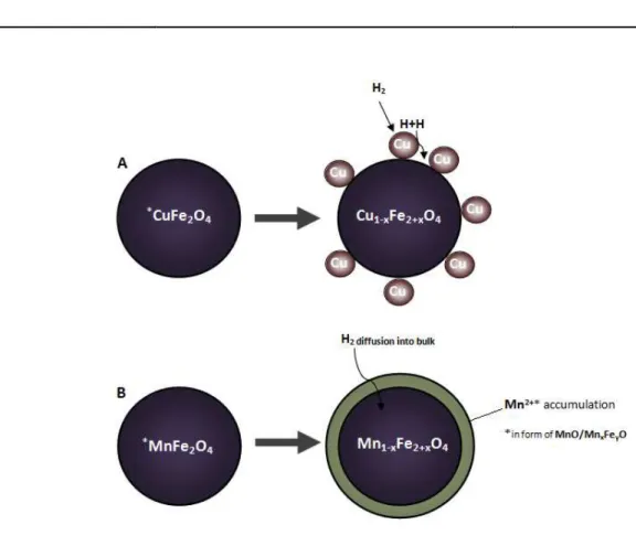
Cu0) formées dans l’étape précédente de réduction. On en conclu que plus de Co et Cu sont présents dans le matériau final M-modifié, moins de matériau sera disponible sous sa forme réoxydée pour être réduit dans les cycles successifs.
En conclusion: bien que plusieurs matériaux améliorés de cyclage redox aient été identifies, la
compréhension complète de leurs performances et ultérieures études d’optimisation sont nécessaires pour évaluer correctement l’efficacité, l’ingénierie et l’économie du procédé de reformage de l’éthanol par cyclage redox.
INTRODUCTION 24
1. INTRODUCTION
Current processes for the industrial production of hydrogen are mainly based on the reforming of natural gas/naphtha or coil gasification. Such processes are highly energy demanding. Hence, less energy-intensive and more sustainable technologies, exploiting renewable feedstocks (such as biomass, bio-alcohols and water) and renewable primary energy sources (e.g. sunlight, wind, wave or hydro-power), appear to be very attractive for both industry and consumer applications. A variety of new technologies offering a non-fossil based route for hydrogen production are in a different stage of development, and each offers unique opportunities, benefits and challenges.1–10
Chemical-Loop Steam Reforming is one of the possible ways to produce H2 starting from
either conventional or renewable sources. Differently from classical reforming, separation costs can be avoided by splitting the process into two alternated steps in order to detach H2
and COx streams. One of the advantages of this technology relates to its feedstock
flexibility. The chemical-loop process can be performed using a number of different reductants, such as gas resulting from coal11or biomass12–14 gasification, light hydrocarbons reforming,15 methane,16–18 CH4/CO2 and CH4/H2 mixture,18,19 pyrolysis oil,20,21 methanol22
and pure H2 (as a method for H2 storage).23,24 Furthermore, the nature of the oxide, used as
the ionic oxygen and electron carrier, and the reaction conditions are important parameters since they determine the potential for low costs and high efficiency of this process in order to have a commercial impact.
1.1. Hydrogen applications
Hydrogen is one of the key starting materials used in the chemical industry with an annual worldwide production of about 50 million tonnes. Currently, the largest amount (~95%) of the total manufactured hydrogen is consumed mainly by two industrial segments: the chemical sector, accounting for 65% of the market share (ammonia and methanol synthesis ~63%; liquid hydrocarbons and higher alcohols synthesis ~2%) and the refining sector, which accounts for 30% of the market share (hydrotreating and hydrocracking processes for
INTRODUCTION 25
obtaining high grade petrochemical products). The other present uses, with ~5% of the total consumption, include the food industry (sorbitol and fat processing), the metallurgical industry (direct reduction of iron ore), the semiconductor industry, and etc (Figure 1-1). In conclusion, there is a fast-growing need for increased hydrogen production, since H2 itself
may become an important “energy vector” with key applications as a carbon free fuel and as a fuel for hydrogen driven fuel cells for automotive uses. However, there are still several major problems to be overcome before it can be used in this way, including its manufacture, storage and distribution.
Figure 1-1. Main segments of hydrogen consumption
1.1.1. Fuel cells
Fuel cells are devices that generate electricity based on a chemical reaction and are often referred to as continuously operating batteries. They exploit electrolysis reactions in a similar manner to traditional batteries however the reagents are constantly supplied to the cell, which actually and determines its difference compared to the traditional dischargeable batteries. There are several kinds of fuel cells though the main operating principle remains
INTRODUCTION 26
latter ones migrate through the electrolyte to the cathode (2), where each H+ ion combines with the oxygen to form water (5) (also emitting heat), while the electrons run through the electrical circuit (4), producing a current (3) (Figure 1-2).
Figure 1-2. General scheme of the fuel cell technology
Nevertheless, its applications can vary depending on the type of hydrogen fed to the anode (they can be chemical elements containing hydrogen) and the nature of the electrolytes (Figure 1-3).
Figure 1-3. Lower segment: main application of the fuel cell technology; Upper segment: fuel and fuel cell types (taken from https://ec.europa.eu):
• AFC: Alkaline (especially in the space sector)
• PEMFC: Polymer Exchange Membrane
• DMFC: Direct Membrane
INTRODUCTION 27
• MCFC: Molten Carbonate
• SOFC: Solid Oxide
1.2. Hydrogen production
1.2.1. Common feedstocks
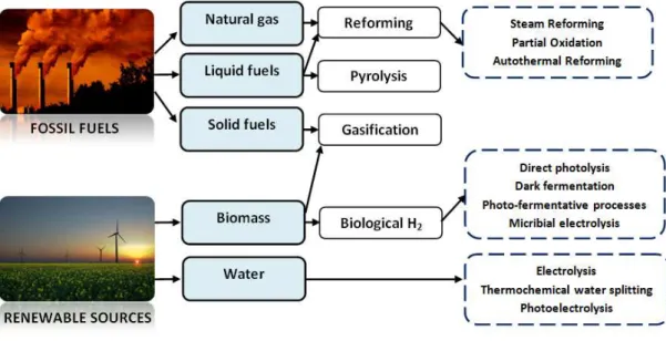
Hydrogen can be produced from different resources including conventional fossil fuels, as natural gas, naphtha and coal, or either using renewable sources such as wind, solar, geothermal, biomass and etc. A variety of new technologies offering a non-fossil based route for hydrogen production are in a different stage of development, and each offers unique opportunities, benefits and challenges. A list of the various feedstocks and process technologies is presented in Figure 1-4.
Figure 1-4. Summary of the various feedstocks and process alternatives for H2 production
INTRODUCTION 28
Hydrogen can be produced using a number of different processes (as illustrated in Figure 1-5). Thermochemical processes use heat and chemical reactions to release hydrogen from organic materials such as fossil fuels and biomass. Water (H2O) can be split into hydrogen
(H2) and oxygen (O2) using electrolysis or solar energy. Microorganisms such as bacteria and
algae can produce hydrogen through biological processes. This session encompasses the most relevant information about the existing processes to manufacture hydrogen.
Figure 1-5. An overview of existing hydrogen production processes from different sources
1.2.3. Hydrogen via Reforming Processes
Reforming processes are based on the endothermic or exothermic conversion of the feedstock materials with H2O/CO2/O2 into synthetic gas mixture (CO+H2). The most
commonly used feedstocks for the reforming processes are methane or either other light hydrocarbons obtained from oil. Several chemical processes have been developed in order to produce hydrogen via reforming route:
1) Steam Reforming (SMR), 2) Auto Thermal reforming (ATR), 3) Partial Oxidation (POX),
4) Dry Reforming of methane (DMR), 5) Combined Reforming of Methane (CMR),
INTRODUCTION 29
6) Reforming with Membrane,
7) Tri-Reforming of Methane (TMR)25.
The first three are widely used industrial processes, whereas the last four are recent innovative processes developed with the aim to minimize environmental impact and energy consumption together with the improvements of already existing methods.
Steam Methane Reforming (SMR) and Water Gas Shift (WGS) reaction
Steam Methane Reforming (SMR) is the most common way to produce hydrogen rich syngas mixture (H2+ CO). A conventional steam reformer unit consists of several hundred
fixed-bed reactor tubes filled with a catalyst, which can vary in its size and geometry. High temperatures (> 600°C) and low pressures favour the formation of the H2 and CO products
(Le Chatelier's Principle). However, in practice, the natural gas steam reformer is operated under the pressure of about 20-30 atm (for kinetic reasons) with an exit temperature of 800-870°C (but the tube wall temperature can range from 700°C up to a maximum hot spot of 920°C), where methane and steam are converted into synthesis gas. Primary steam reforming catalysts are nickel based catalyst: 10-20% Ni supported on α−Al2O3, calcium or
magnesium aluminate with a life time from 3 to 5 years. Cobalt and noble metals are also active, but more expensive. Attempts to use non-metallic catalysts have not had commercial success because of the low activity. The catalyst properties are dictated by the severe operating conditions, i.e. temperatures of 450-950oC and steam partial pressures of up to 30 bar.
Normally, the subsequent stage of the SMR process includes WGS reactions which further convert carbon monoxide to carbon dioxide, while generating more hydrogen.
INTRODUCTION 30
In the first stage, refers to a high temperature shift reaction, the gas is mixed with steam and passed over an Fe/Cr or Fe/Cr/Mg mixed oxide catalyst at T= 300-450oC in a fixed bed reactor; which decreases the carbon monoxide concentration down to 2-3%. In the second stage, the low temperature shift reaction, the mixture of gases is passed over a Cu/Zn oxide catalyst at T=190-220oC, where the carbon monoxide concentration is reduced to 0.1-0.2%. Further hydrogen purification can be achieved using:
- Methanation
- Pressure Swing Adsorption (PSA)
- Membrane reactors and etc.
Steam Naphtha Reforming
If naphtha is used as the feedstock, an extra reforming stage is needed. The naphtha is heated to form a vapour, mixed with steam and passed through tubes, heated at T=450-500oC and packed with a catalyst, nickel supported on a mixture of aluminium and
magnesium oxides. The main product is methane together with carbon oxides (COx), which
then processed by SMR, as if it was natural gas, followed by the shift reaction.
Dry Methane Reforming (DMR)
The DMR process is characterized by a very low intrinsic activity, in addition to the simultaneous occurrence of the reverse water gas shift (RWGS) reaction resulting in a syngas ratio less than unity. Dry reforming of methane has been investigated with noble (Rh, Ru, Pd and Pt) and non-noble metal (Ni, Co and Fe) based catalysts. Noble metal catalysts have drawn attention for their superior coking resistance, higher stability and
+
→
+
∆ ° = − 42 /
INTRODUCTION 31
activity especially for higher temperature applications. However, for large scale industrial applications, development of the active catalyst is still under investigation.
Autothermal Reforming (ATR)
Autothermal reforming (ATR) is an important industrial process used to produce syngas with a low H2/CO ratio (from 1.5 to 3) desired for synthesis of methanol and higher
molecular weight hydrocarbons (via Fischer-Tropsch process). The main concept based on a combination of non-catalytic partial oxidation and adiabatic catalytic steam reforming, where the reactor temperature is maintained using the heat emitted from the partial oxidation of the hydrocarbon feedstock, typically methane, with a sub-stoichiometric amount of oxygen.
This process was developed by Haldor Topsoe A/S with the aim to perform the POx (partial oxidation) and the SR (steam reforming) in a single ATR reactor. The very high temperatures in the ATR unit require a high thermal stability catalyst, which is typically the nickel-based catalyst on a stabilized Al or Mg-Al support.
Partial oxidation (POX)
An alternative way to produce hydrogen based on the partial oxidation of a sub-stoichiometric fuel-air mixture which results in a formation of H2-rich syngas. Partial
oxidation is an exothermic reaction and, thus, considered to be more economically feasible than the processes of steam or dry reforming. The exothermic nature of reaction has certain drawbacks that it induces hot spots on catalyst arising from a poor heat removal rate
+
→ 3
+
∆ ° = +225,4 /
+
3
2
→
+ 2
∆ ° = −520,0 /
+
1
INTRODUCTION 32
causing the difficulties in operation control. A difference is made between thermal partial
oxidation (TPOX) and catalytic partial oxidation (CPOX). Thermal (non-catalytic) Partial Oxidation
TPOX is a non-catalytic process in which the feed is partially combusted with a sub-stoichiometric amount of air, oxygen, or enriched air to obtain CO+H2 mixture, where the
production of syngas depends on the oxygen/fuel ratio at operating temperature range of 1200-1500˚C. Feedstock is used for the TPOX can be almost any carbonaceous material, from natural gas through liquid feeds such as fuel oils and gas oils as well as coal. A non-catalytic partial oxidation process was developed by Texaco and Shell which results in high syngas yields at high temperature and pressures26.
Catalytic Partial Oxidation
CPOX is a catalytic process in which the feed with sub-stoichiometric amount of oxygen (or air) is catalytically converted into CO+H2 mixture. The use of a catalyst lowers the required
reaction temperature down to 800-900˚C. Commonly used catalysts are noble (Pt, Rh, Ir, Pd) or non-noble (Ni, Co) metal based catalysts. Catalytic partial oxidation can be performed only if a sulfur content of the feed is below 50 ppm, since the higher sulfur content would poison the catalyst (in such case non-catalytic partial oxidation is more suitable for the use).
1.2.4. Hydrogen via Chemical-Loop (CL) processes
CL processes are based on the looping approach that usually consists of two temporarily/spatially separated steps: reduction and re-oxidation. During the reduction step, a transfer of the oxygen to the fuel mediated by a metal oxide carrier material (MexOy), which is put in a contact with a reducing stream, thus being reduced and at the
same time converting the fuel into products, mainly COx, H2O and H2. Subsequent oxidation
step is performed over the previously reduced material (Me/MexOy-δ) with air/H2O (water
splitting) in order to restore its original oxidation state (MexOy) and to produce H2 (when the
INTRODUCTION 33
steam are used to regenerate the oxygen carrier material. Re-oxidation step performed with air is varied between Steam Reforming integrated to Chemical-Looping Combustion
process (SR-CLC), where CLC is used to energy supply needed for the conventional catalytic
steam reforming and Chemical-Looping Reforming process (CLR) where primary products from the Chemical-Looping system are H2 and CO. Other processes use the property of
some oxygen depleted materials to react with water steam to generate pure H2, also known
as “water splitting”. In this category, it can be found Chemical-Looping Hydrogen (CLH) or
One Step Decarbonization (OSD) processes, and the so-called Chemical-Looping Gasification
technologies: Syngas Chemical-Looping process (SCL) and Coal Direct Chemical-Looping
process (CDCL) and etc. Usually the later processes need several oxidation steps, like an air
treatment, which sometimes required for the final regeneration of the oxygen carrier material27. One of the fundamental parameters, that determines the overall efficiency of many chemical looping processes, lies in the effectiveness of the oxygen carrier materials. Hence many research groups focus their attention on further improving the activity and the stability of oxygen carrying materials.
Chemical-Loop Reforming (CLR) for Hydrogen Generation
CLR for Hydrogen Generation is developed as an alternative way to produce H2 starting
from either conventional or renewable sources. The Chemical-Loop process can be performed using a number of different reductants, such as gas resulting from coal11 or biomass12–14 gasification, light hydrocarbons reforming,15 methane,16–18 CH4/CO2 and CH4/H2
mixture,18,19 pyrolysis oil,20,21 methanol22 and pure H2 (as a method for H2
storage).23,24Differently from a classical reforming, separation costs can be avoided by splitting the process into two/three alternated steps in order to detach H2/COx streams and
fully re-oxidize the oxygen carrier material (Figure 1-6). Generally, the reducing fuel (CnH2m)
is fed to the FR, where it reacts with the oxygen carrier material (MxOy) according to the
INTRODUCTION 34 (FR) – (n+m/2) MxOy + CnH2m→ (n+m/2) MxOy-2 + m H2O + n CO2
After the first step, previously reduced oxygen carrier material is transferred to the steam reactor (SR), where it is oxidized by a water steam to restore its original oxidation state:
(SR) – (n+m/2) MxOy-2 + m H2O → (n+m/2) MxOy-1 + m H2
A general statement, made on the basis of the results obtained independently by several research groups: as the oxygen ratio in the system decreases, there is a higher tendency towards carbon formation, which in its turn leads to the lowering of the purity of the produced hydrogen. According to Cho et al. 28, the rate of carbon formation increased rapidly when more than 80 % of the available oxygen in the Ni-based oxygen carrier was consumed. Galvita and Sundmacher reported that a maximum Fe reduction of 60 % largely minimized carbon formation and a high purity hydrogen stream (< 20 ppm CO) could be obtained29.
Usually, the difficulty to re-obtain original oxidation state of the oxygen carrier material by means of only water steam can lead to the necessity of an additional oxidation step, like an air treatment:
(AR) – (n+m/2) MxOy-1 + ½ O2→ (n+m/2) MxOy
Oxygen carrier material (MxOy), in its fully oxidized form, is further re-circulated to the fuel
INTRODUCTION 35
Figure 1-6. Schematic representation of CLR for Hydrogen Generation over Fe-based oxygen carrier material Important aspects for the overall effectiveness of the process lie in the choice of operation conditions, reactors design and identification of suitable candidates to be used as corresponding oxygen carrier materials. Appropriate oxygen carriers should have sufficiently high conversion rates in redox reactions, high agglomeration/sintering resistance, complete fuel conversion, negligible carbon deposition, and be economical and environmentally friendly30.
Oxygen carrier materials
As it has been already mentioned, a choice of the suitable oxygen carrier material for any type of Chemical-Loop process is an important parameter which has to be considered, taking into account several properties: reaction kinetics, thermodynamic feasibility of oxygen transfer, redox properties, oxygen content, long term recyclability and durability, attrition resistance, heat capacity, melting points, tendency to form coke, resistance to carbon deposition, low cost, toxicity and etc 27. However, one of the most important requirements is the thermodynamic aspect of a suitable redox couple – MxOy/Mx, which
determines the final effectiveness of the process together with a choice of operating conditions. Figure 1-7 shows the Gibbs free energies (ΔG) as a function of temperature for
INTRODUCTION 36
some frequently studied oxygen carrier materials; moreover, the values for oxygen transport capacity are listed in Table 1-1.
Figure 1-7. Gibbs free energies for the following redox reactions31: I. Reduction of oxygen carrier with a CH4-fuel: a - CH4 total combustion (CH4 + 4/y MxOy → CO2 + 2 H2O + 4x/y M), b - CH4 partial oxidation (CH4 + 1/y MxOy→ CO + 2H2 + x/y M); II. Re-oxidation of reduced oxygen carrier with a steam/air: c – H2O oxidation (x M + y H2O → MxOy + y H2), d - air oxidation
(x M + y/2 O2 → MxOy), *see Table 1-1 for the numeric legends
Table 1-1. Common redox couples31
*
Redox couple Oxygen transport capacity, kg/kg-metal
1 NiO/Ni 0.27
2 CuO/Cu 0.25
INTRODUCTION 37 4 MnO2/Mn 0.58 5 Co3O4/Co 0.36 6 WO3/W 0.26 7 ZnO/Zn 0.24 8 SnO/Sn 0.13 9 In2O3/In 0.21 10 MoO2/Mo 0.33 11 V2O5/V 0.78 12 CeO2/Ce2O3 0.06
According to the listed data, oxygen carrier materials can be conventionally divided into the materials that are capable to partially oxidize methane, like ZnO/Zn, V2O5/V or CeO2/Ce2O3.
Whereas some redox couples, as NiO/Ni, Co3O4/Co and CuO/Cu, favor total methane
oxidation; in addition, their further re-oxidation is also favorable over a wide temperature range, as supported by the negative ΔG values in Figure. Thus, oxygen carrier materials based on the Ni, Co and Cu elements are often regarded as good candidates for Chemical-Loop applications.
A comprehensive review on different oxygen carrier materials for the hydrogen production via Chemical-Loop processes was recently published by Protasova et al30. The review encompasses information on the different perovskites and Ni/Fe/Cu/Ce-based oxygen carrier materials. Perovskites showed good results for the partial oxidation of methane; whereas with Fe-based materials promising results also have been obtained (moreover they are considered to replace Ni-based oxygen carriers because of their price and toxicity). Several research groups have been exploring modifications of simple iron oxide (Fe3O4 and
Fe2O3) in order to prevent deactivation,32 to lower the operating temperature33 and to
increase the structural stability and reducibility,34,35 the reaction rate for oxidation and total efficiency of the process.36,37 Several studies were dedicated to different metal additives to iron oxide.38,39 In addition, ternary metal systems have also been considered in the search for a better synergetic effect.40,41 Several research groups have been investigated the effect
INTRODUCTION 38
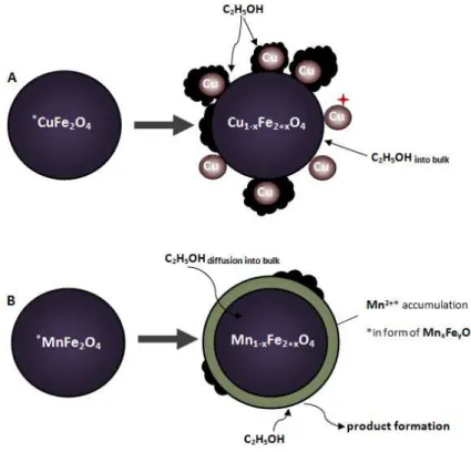
of various M-additives on the stability and redox behavior of iron oxide for chemical hydrogen storage using Pd, Pt, Rh, Ru, Al, Ce, Ti, Zr42 and Al, Cr, Zr, Ga, V , Mo43. And it was found out that Pd, Pt, Rh and Ru additives have an effect on promoting the reduction and lowering the re-oxidation temperature of iron oxide. At the same time, Al, Ce, Ti, Zr, Cr, Ga and V additives prevent deactivation and sintering of iron oxide during repeated redox cycles. Some recent studies on developing of the novel and efficient oxygen carrier materials for Chemical-Loop applications highlight the special interest in spinel oxides16,24,32,36,37,44–56 which, first of all, can be explained by their ability to form thermodynamically stable spinel oxides which allow to re-obtain the initial spinel phase upon cycling and in turn increase the stability of the looping material itself.
1.3. Spinel oxides: AB2O4
Spinel oxides with a generic formula of AB2O4 are chemically and thermally stable materials
suitable for variety applications including catalysis (Figure 1-8). Many of them are used as magnetic pigments57, nanodevices58, photoelectric devices59, sensors and microwave devices60,61. Besides, spinel ferrites (AFe2O4) are attractive because of the importance in
ferrofluids62,63, magnetic drug delivery64,65 and hyperthermia for cancer treatment66. At the same time, they have well-established catalytic properties for many reactions, such as: oxidative dehydrogenation of hydrocarbons67,68, decomposition of alcohols69,70, selective oxidation reactions71,72,73, CO74 and CO2 removal75, VOCs76 and propane total oxidation77,
methanol steam reforming78, hydrogen peroxide decomposition79,80, NOx selective
reduction81 and WGS reaction82,83. The catalytic effectiveness of these systems explained by the ability of metallic ions to migrate between the sub-lattices without altering the structure, which makes the catalyst efficient for many organic transformation reactions84. Versatile catalytic properties are dependent on the chemical composition and nature of substituted ions, charges and their distribution among the Oh and Td sites, and this is
INTRODUCTION 39
Figure 1-8. Main fields of the spinel oxide application
Structure of AB2O4 oxides
The crystallographic structure of spinel oxide group is formed by a nearly closed-packed face centered cubic (fcc) of anions (Figure 1-9) with two unequivalent sites for cations, which differ in oxygen coordination89,88. A tetrahedral site, AO4, is comprised of the cation
at the center of a cube and four oxygen atoms in the nonadjacent corners. The octahedral site, BO6, consists of a cation surrounded by six oxygen atoms, two along each dimensional
axis, to form a octahedron 88,90. The preference of the individual ions for the two types of lattice sites (OhvsTd) is determined by:
• the ionic radii of the specific ions;
• the size of the interstices;
• the temperature;
• the orbital preference for specific coordination 88
On the basis of a cation valency occupation in the molecule of the spinel oxide they can be subdivided into three basic types:
1. M12+M23+O4, (2-3 spinel): Fe3O4, NiFe2O4, CuFe2O4
INTRODUCTION 40
3. M16+M21+O4, (6-1 spinel): MoLi2O4, WAg2O4
However, the most common type is 2-3 spinel which comprises of M1(II) and M2(III) metal cations in the molecular unit.
Figure 1-9. Spinel oxide unit cell
According to the distribution of A and B cations between Td and Oh sites, there are two
types of spinel oxides: normal and inverse spinels. In the normal spinel, the A cations (divalent) occupy all the tetrahedral sites, and the B cations (trivalent) fill the octahedral sites. Since tetrahedral holes are smaller than octahedral holes, the A ions should be smaller than the B ions. In fact, this condition is not fulfilled in many spinels, and thus there is another type of spinels, which is more common in nature, so called the inverse spinel, just to indicate that they were the opposite of what had already been described. In inverse
spinel, the B cations occupy the tetrahedral sites, and the octahedral sites contains a
mixture of B and A cations89,91,88. Important parameter which is used to describe the degree of spinel inversion denotes as an inversion parameter (δ), and is equal to 0 in a case of the
INTRODUCTION 41 1.4. Aim of the research project
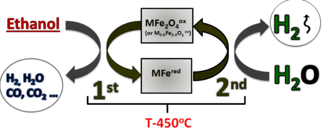
The research work presented here investigates a new process, named as Chemical-Loop Reforming (CLR) process, to produce “clean H2” with an inherent COx separation. The main
principle of the CLR process is that an oxygen-storage material is first reduced by ethanol stream (T-450oC), and then re-oxidized by water (T-450oC) to produce hydrogen and to restore the original oxidation state of the looping-material (Figure 1-10).
Figure 1-10. The chemical-loop reforming of ethanol over modified ferrospinels The choice of ethanol as a reducing agent has its several advantages:
- The use of bio-alcohols in cycle reforming has not yet been much studied in literature;
- Ethanol can be obtained from biomasses, that might contribute to unlink the production of hydrogen from fossil fuels;
- Ethanol is a non-toxic liquid, easy to transport and handle, relatively stable at room temperature.
The initial task of the project is to define conditions and materials that may lead to an optimized process, allowing producing a hydrogen stream that does not require any additional purification or separation treatment. Hence, different M-modified spinel-type mixed oxides (TYPE I – MFe2O4 and TYPE II – M0.6Fe2.4Oy) are synthesized and tested as
potentially attractive ionic oxygen and electron carrier looping materials to generate hydrogen by oxidation with steam, after a reductive step carried out with ethanol.
INTRODUCTION 42
Particularly, the focus on the reactivity behavior of secondary/ternary materials explained by their ability to form thermodynamically stable spinel oxides which allow us to re-obtain the initial spinel phase upon cycling and in turn increase the stability of looping material itself. The composition of MFe2O4 and M0.6Fe2.4Oy ferrospinels is varied in between
transition metals: Co, Mn, Cu or Cu/Co, Cu/Mn, Co/Mn and alkaline earth metals: Ca, Mg. The aim of the following modifications is to pursue a higher selectivity to some valuable chemicals produced on the 1st reduction step along with a high purity H2 produced during
the 2nd re-oxidation step.
The secondary task is to explore the chemistry of the process, by means of both in-situ and ex-situ techniques, and the characteristics of the mixed oxides, in terms of redox properties, morphology and chemical-physical features which also encompasses the solid-state chemistry investigations of the fresh and cycled looping materials.
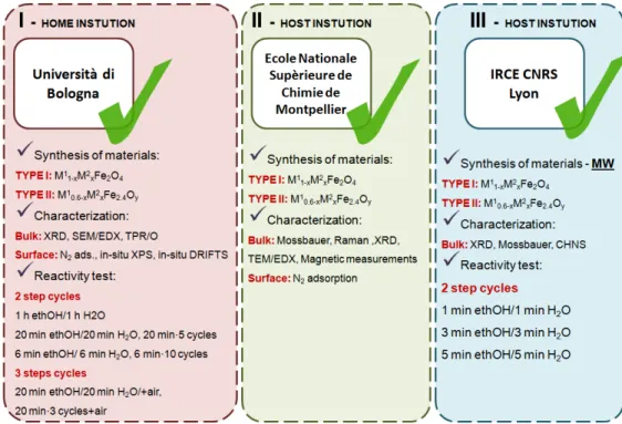
This research was apportioned between three institutions, all details about the accomplished work are summarized in Figure 1-11.
CHARACTERIZATION TECHNIQUES AND SET-UP OF LABORATORY PLANT 43
2. CHARACTERIZATION TECHNIQUES AND SET-UP OF LABORATORY PLANT
This chapter includes the information on several characterization techniques used to study bulk and surface properties of the fresh/used looping materials (ferrospinels of TYPE I – MFe2O4 and TYPE II – M0.6Fe2.4Oy, where M: Cu, Co, Mn, Mg, Ca and Cu/Co, Cu/Mn, Co/Mn).
All the solids were tested in a laboratory-scale plant designed to carry out the Ethanol Chemical-Loop Reforming experiments. In addition, the chapter contains a description of the analysis method used for identification and quantification of the reactants/products including the calculation protocols.
2.1. X-ray diffraction (XRD)
X-ray diffraction is a primary technique used to determine nature of the crystalline phases and to measure a size, shape and internal stress of small crystalline regions. Information on the sample is given by the position, intensity, sharpness and width of the diffraction lines. The diffraction angle 2θ and the spacing between two planes (h,k,l) d are related by the Bragg’s law:
2 d sinθ = n λ
Where:
λ – the wavelength of incident X-ray n – the diffraction order
CHARACTERIZATION TECHNIQUES AND SET-UP OF LABORATORY PLANT 44
Figure 2-1. Schematization of the X-ray diffraction experimental setup
In the present study, the powder X-ray diffraction (XRD) patterns were measured on Bruker D8 Advance diffractometer (using Cu Kα radiation with λ = 1.5406 Å) with a Bragg-Brentano
geometry and equipped with a Bruker Lynx Eye detector. The data were recorded varied from 5 to 80o 2θ diffraction angle with an acquisition time of 1 s per each step (0,01 degree).
The Debye-Scherrer equation was used for the calculation of a crystallite size, which is related to the FWHM (Full Width at Half Maximum) through the formula:
=
!"
Where:
τ – the mean size of the ordered (crystalline) domains, which may be smaller or equal to the grain size K– the dimensionless shape factor, with a value close to unity (Kis typically eq. to 0.9)
λ– the X-ray wavelength
β– the line broadening at half the maximum intensity (FWHM), after subtracting the instrumental line broadening
CHARACTERIZATION TECHNIQUES AND SET-UP OF LABORATORY PLANT 45
TOPAS-4.2 program was used to refine the unit cell parameters of the crystalline phases and to calculate the relative phase content in the fresh/used samples. The calculations are based on the Rietveld refinement method, which permits the reproduction ofthe whole diffractogram, through the optimization of both structural (peak position and intensity) and non-structural (peaks shape) data.
2.2. Raman Spectroscopy
Raman spectroscopy is used to observe the differences in the vibrational modes of the samples with respect to the composition which causes local distortions that are not seen by x-ray diffraction. Raman spectra were recorded using a Bruker spectrometer with a 633 nm He/Ne laser source (filter: Plaser ÷10; slit 100 μm) equipped with a microscope (50X lens).
Each spectrum was taken with 300 sec exposure time and 1 accumulation.
Figure 2-2. Schematic identifying light scattering after laser exposure on a sample surface
2.3. Mössbauer Spectroscopy
The Mössbauer effect consists of the "recoilless" emission of γ-ray photons from certain radioactive nuclei, and the selective re-absorption of those photons by other nearby nuclei. The process is sensitive to small differences between the structure of the emitting and the absorbing nuclei. Mössbauer spectroscopy uses this phenomenon to explore the nuclear and atomic structure of materials.
CHARACTERIZATION TECHNIQUES AND SET-UP OF LABORATORY PLANT 46
Through Mössbauer spectroscopy it is possible to obtain important information on the oxidation state and the structure of Fe species in a solid. The main nuclear interactions used for the interpretation of the resonance spectra are three:
• Isomer Shift (IS), which is the shift in nuclear energy levels induced by the static charge of nearby atomic electrons
• Quadrupole Splitting (QS) which is the shift in nuclear energy levels induced by a strong electric field gradient due to nearly electrons and
• Magnetic (or Hyperfine) Splitting (HS) corresponding to the energy level splitting in a nucleus due to the magnetic fields induced by the nearby atomic electrons.
The Mössbauer spectrometer was a homemade apparatus using a 57Co/Rh γ-ray source and
a conventional constant acceleration Mössbauer spectrometer. The solids were pressed into thin discs and the analysis took about one day to be completed (in some cases it can require even longer time).
Isomer shifts were given with respect to α-Fe. All spectra were taken at room temperature and ambient atmosphere; samples were diluted in sucrose at about 50%w concentration.
Integrated areas under individual deconvoluted peaks were used to obtain the relative populations of different iron species, assuming an equal recoil-free fraction for all the species.
The calculations were made using pure Lorentzian functions. The parameters characterizing a Mössbauer spectrum were determined by least-squares fitting and the goodness of the fit statistics by minimizing the χ2 quadratic function:
# = ∑ (&'()* &'+,-)/ &' +,-0 · 2 3*4 Where:
N - the number of measured points
K - the number of the parameters to be determined