DTT
Divertor Tokamak Test facility
Interim Design Report
Summary
A milestone along the roadmap
to the realisation of fusion energy
ISBN: 978-88-8286-370-8Italian National Agency for New Technologies, Energy and Sustainable Economic Development
DTT
Divertor Tokamak Test facility
Interim Design Report
SUMMARY
A milestone along the roadmap
to the realisation of fusion energy
September 2018
DTT
Divertor Tokamak Test facility – Interim Design Report - Summary
Italian National Agency for New Technologies, Energy and Sustainable Economic Development Edited by Aldo Pizzuto, ENEA
ISBN: 978-88-8286-370-8
Printed in September 2018 at ENEA Frascati Research Center Via Enrico Fermi 45, 00044 Frascati (Roma), Italy
The project proposal DTT, Divertor Tokamak Test facility, issued in 2015, is described in analytical form in the volume “DTT Divertor Tokamak Test facility. Project Proposal” published by ENEA in July 2015, ISBN: 978-88-8286-318-0, also available in electronic format on the web site
http://fsn-fusphy.frascati.enea.it/DTT_ProjectProposal_July2015.pdf.
The DTT proposal is also described in a Special Section of Fusion Engineering and Design, Vol. 122, 2017, pp. 253-294 and e1-e25.
The complex and articulated project, involving about a hundred researchers from Italian and foreign universities and laboratories, was coordinated by R. Albanese (Università di Napoli Federico II, Italy and CREATE, Italy), F. Crisanti (ENEA, Italy), R. Martone (Università della Campania “L. Vanvitelli”, Italy and CREATE, Italy) and
A. Pizzuto (ENEA, Italy).
Thanks to the qualification and dedication of the team, the project was able to represent an innovative and thorough proposal in the road map towards the implementation of energy from controlled thermonuclear fusion.
Afterword, the project was approved by the Italian authorities, on the basis of a financial plan based on ministerial and regional financing and on a wide European support obtained within the framework of the European Plan for Infrastructure Investments.
Then, a number of important further steps have been made, including the review of some of the machine parameters, the revision of some critical subsystem of the project, the selection of the site, the creation of a first provisional organizational and managerial structure.
Aim of this note is to provide the key overall data of the complex and articulated project as appears after the revision phase carried out in the recent past.
The coordination team.
R. Albanese, F. Crisanti, R. Martone, P. Martin, A. Pizzuto.
Acknowledgements
The Interim Design activity, summarized in this document, is based on the activity carried out in the past and reported in the “Project Proposal” (DTT Divertor Tokamak Test facility - Project Proposal, Ed. Aldo Pizzuto, ENEA, ISBN: 978-88-8286-318-0, July 2015).
A cordial acknowledgement to all the contributors (and their institutions) of that important activity, here following listed:
ENEA, Italy: L. Affinito, A. Anemona, M. L. Apicella, P. Batistoni, G. Calabrò, A. Cardinali, S. Ceccuzzi, C. Centioli, V. Corato, P. Costa, F. Crisanti, A. Cucchiaro, A. Della Corte, G. De Marzi, A. Di Zenobio, C. Fiamozzi Zignani, L. Gabellieri, A. Lampasi, G. Maddaluno, G. Maffia, D. Marocco, G. Mazzitelli, G. Messina, F. Mirizzi, M. Moneti, L. Muzzi, A. Pizzuto, G. Ramogida, G.L. Ravera, R. Righetti, S. Roccella, F. Starace, G. Tomassetti, A.A. Tuccillo, O. Tudisco, S. Turtù, S. Villari, B. Viola, V. Vitale, G. Vlad, P. Zito, F. Zonca
ENEA-CNR - IFP, Italy: A. Bruschi, D. Farina, L. Figini, S. Garavaglia, G. Granucci, M. Lontano, D. Micheletti, S. Nowak, C. Sozzi
ENEA-CREATE, Italy: R. Albanese, R. Ambrosino, L. Barbato, S. Ciattaglia, D. Coccorese, V. Coccorese, M. de Magistris, G. Di Gironimo, V. P. Loschiavo, R. Martone, D. Marzullo, S. Mastrostefano, S. Minucci, R. Mozzillo, R. Palmaccio, V. Pericoli-Ridolfini, A. Pironti, G. Rubinacci, A. Tarallo, S. Ventre, F. Villone
ENEA-Politecnico di Torino, Italy: R. Maggiora, D. Milanesio
ENEA-RFX, Italy: P. Agostinetti, T. Bolzonella, L. Carraro, A. Fassina, P. Franz, E. Gaio, F. Gnesotto, P. Innocente, A. Luchetta, G. Manduchi, L. Marrelli, P. Martin, S. Peruzzo, R. Piovan, M. E. Puiatti, G. Spizzo, P. Scarin, P. Sonato, M. Spolaore, V. Toigo, M. Valisa, L. Zanotto
ENEA-Università degli Studi di Milano - Bicocca, Italy: G. Gorini
CEA, IRFM, France: G. Giruzzi
CRPP - EPFL, Switzerland: B. Duval, H. Reimerdes
FOM-DIFFER, The Netherlands: M. de Baar
IPPLM, Poland: R. Zagórski.
An acknowledgement goes also to the following additional people and institutions for their significant contribution to that activity:
Leaders, project boards and entire teams of the following EUROfusion work packages: “WPDTT1 - Assessment of alternative divertor geometries and liquid metals PFCs” and “WPDTT2 - Definition and Design of the Divertor Tokamak Test Facility”;
EUROfusion General Assembly, leader and staff; EUROfusion, Department of Power Plant Physics and Technology; EUROfusion ITER Physics Department; Università degli Studi di Roma Tor Vergata; F4E; ITER Machine Operation Officer; ENEA Create Staff, CEA;
K. Lackner and E. Salpietro, Jiangang Li.
The present document does not represent the opinion of CEA, CRPP-EPFL, EUROfusion, F4E, FOM-DIFFER, IPPLM, ITER or any non-Italian EUROfusion beneficiary.
Contributors
ENEA, Italy: F. Crisanti, A. Di Zenobio, A. Lampasi, G. Maddaluno,
G. Mazzitelli, A. Pizzuto, G.M. Polli, G. Ramogida, P. Rossi, S. Sandri, S. Villari, V. Vitale
ENEA- CNR - IFP, Italy: G. Granucci
ENEA-CREATE, Italy: R. Albanese, R. Ambrosino, G. Di Gironimo, R. Martone
ENEA-Politecnico di Torino, Italy: R. Zanino
6
Synopsis
The establishment of the EUROfusion Consortium marks a big step in the roadmap toward the realisation of fusion energy with a demonstration plant DEMO around 2050.
One of the main challenges in the roadmap is to develop a heat and power exhaust system able to withstand the large loads expected in the divertor of a fusion power plant. Therefore, in parallel with the programme aimed to optimise the operation with a conventional divertor based on detached conditions to be tested in ITER, EUROfusion has launched a dedicated project to investigate alternative power exhaust solutions for DEMO. In this regard, the design of a new machine named “Divertor Tokamak Test facility” (DTT), to be able of integrating all relevant physics and technology issues has been considered very crucial to assess possible alternative solutions, including advanced magnetic configurations and liquid metal divertors.
The original DTT project proposal has been carried out by more than one hundred scientists from ENEA, CNR and Universities, with the support of some European Labs and the contribution of scientists from several European Labs. The results are collected in “DTT-Divertor Tokamak Test facility. Project Proposal”, ISBN 978-88-8286-318-0, published in 2015 (DTT “Blue Book”) [1] and published in several papers, including the Special Issue in Fusion Engineering and Design, November 2017 [2].
After the Blue Book was published, the DTT team continued its intense activity in order to finalize the project and the organization; the main aims were organizational and financial objectives (site selection, organizational structure, cost revision, etc.) and, in addition, technical and design insights (up-down symmetry, parameter settling, review of critical subsystems, etc.).
The new version of the project is described in a new report (titled: “DTT-Divertor Tokamak Test facility. Interim Design Report”, Green Book) to be published by the end of the year; this note summarizes and anticipates the main elements of the new report.
DTT should operate integrating various aspects, with significant power loads, flexible divertors, plasma edge and bulk conditions approaching, as much as possible, those planned for DEMO, in terms of dimensionless
7
parameters. An optimal balance between such requirements and the need to realize the new experiment accomplishing the DEMO timescale has been carried out by means of suitable scoping studies. The outcome of these studies led to the choice of the following parameters: major radius R=2.10 m, aspect ratio A=3.23 (A=R/a, where ‘a’ is the tokamak minor radius), toroidal field BT=6 T, plasma current Ip=5.5 MA, additional power
PTot=45 MW. The machine will have the possibility to test several different
magnetic divertor topologies, in relevant reactor regimes. Different plasma facing materials will be tested (tungsten, liquid metals) up to a power flow in excess of 20 MW/m2. The final target of the experiment is the realization of an integrated solution (bulk and edge plasma) for the power exhaust in view of DEMO. The related studies and experiments will allow a valuable development of innovative technologies in several different fields, with relevant spin off for the industries of all European Countries.
According to the European Road Map, the DTT experiment should start its operation in 2025. To be coherent with this plan, the realization of the device will cover a time of around 7 years, starting from the first tender (during 2018) up to full commissioning and the first plasma (during 2025). The operations should then cover a period of more than 20 years up to the initial phases of the DEMO.
The occupational impact is expected to be significant, with at least 250 people involved for the operation (50 % professionals, 50 % support personnel). In addition, a substantial amount of on-site workers is expected during the construction, as well as large indirect occupational benefits and spin-off opportunities.
All the financial implications for both the construction and the operation have been addressed for the selected site (buildings, electrical grid, maintenance, etc.).
The expected economic impact on the hosting territory is also significant. In addition, the continuous presence of an international scientific staff will cause on the host territory a spin-off linked to the guest family life and activities like lodging, transport, restaurants, schools and so on.
While the European Programme allocated about 60 MEUR in next framework program, the expected total cost for realizing this DTT proposal is estimated to be about 500 MEUR. Half of the amount is covered by a European loan, granted to the Italian Government.
8
DTT is a strategic investment in several key areas of research and innovation, with significant implications on the energy problem, offering a stimulus on higher education and training in many fields of science and engineering. The Italian Government has offered to the European fusion system the opportunity to get complementary funding for a dedicated exhaust facility located in Italy.
This report is a summary of a comprehensive report of the DTT interim project recently revised by an International European team of experts. Namely, its contents have been independently revised and recommended by Chinese experts. It demonstrates the possibility to set up a facility able to bridge the technological gap between the present day devices and the future ITER/DEMO reactors. The DTT scientific project is well framed within the European fusion development roadmap, which plays a crucial role for the development of one of the most promising technologies for an alternative, safe and sustainable new energy source.
9
1. Introduction
One of the main challenges, within the European Fusion Roadmap [3], in view of the construction of a demonstration plant (DEMO, the first nuclear fusion power plant able to provide power to the electricity grid around 2050), is the thermal power on the divertor (the main component of the system for the disposal of the plasma thermal power in a fusion plant). In ITER [4-5] (the International Fusion experiment for magnetically confined plasma, presently under construction in Cadarache, France) it is planned to test the actual possibilities of a “standard” divertor operating in a plasma fully detached condition, i.e. no contact between plasma and first wall of the vessel. Unfortunately, this solution could be unsuitable to be extrapolated to the operating conditions of DEMO and future reactors; then the problem of thermal loads on the divertor may remain particularly critical in the road to the realization of the reactor.
For this reason, within the European Fusion Roadmap, a specific project has been launched, aimed to define and design a Tokamak named “DTT (Divertor Tokamak Test)”. This Tokamak has to carry out a number of scaled experiments, to be integrated with the specific physical condition expected and technological solutions included in DEMO. DTT should retain the possibility of testing different divertor magnetic configurations, including liquid metal divertor targets, and other possible solutions promising to face with the power exhaust problem.
Hereby, the present DTT design proposal refers to a set of parameters suitably selected to reproduce edge conditions as close as possible to those expected in DEMO (in terms of a set of dimensionless parameters characterizing the physics of Scrape Off Layer, SOL, and of the divertor region), while fully fitting (again, in terms of the dimensionless parameters) with DEMO bulk plasma performance. The main parameters of DTT have been selected to ensure maximum flexibility, even within the hard limits of a given budget and, in addition, of a time schedule consistent with the needs of the European Road Map.
10
2. Fusion as a “clean” and “infinite” energy source
Nuclear fusion is the process that powers the sun and the stars, making life on Earth possible. It is called “fusion” since the energy is produced by combining light nuclei (hydrogen isotopes) at extremely high temperatures (15 million degrees ºK in the sun, more than 100 million degrees ºK in laboratory devices). In the fusion process, part of the reactants mass is converted into kinetic energy of the reaction products (helium and a neutron for the deuterium-tritium reaction), which in turn can be used to produce electric energy within a standard steam turbine cycle.
Looking ahead, the nuclear fusion is included among the energy sources able to guarantee the world energy sustainability without CO2 production
(i.e. without contributing directly to the greenhouse effect). Therefore, the fusion can effectively contribute in the future to meet the quick growth of the global energy demand, in fact, expected to more than doubling by 2050, because of the combined effect of the increases of population and energy needs per person in developing countries.
Nuclear fusion, realized in fusion devices in a controlled way, will provide a source of energy:
Environment-friendly: the products of the most promising fusion reaction (Deuterium-Tritium, D-T) are just helium and neutrons. No long-term, radioactive wastes arise and, with a proper choice of materials for the reaction chamber, the radioactivity induced in structural components decays in a relatively short time, compared to the values in carbon-fired plants.
Intrinsically safe: no chain-reaction is possible, since a very small amount of fuel is needed in the vacuum vessel; as a consequence, in case of damage, accident, or loss of control, fusion reactions and heat generation will very rapidly and automatically switch off.
Sustainability: the fuel, deuterium and lithium (the latter produced from lithium inside the reactor), are widely available in nature and virtually unlimited (deuterium is abundant in sea water and lithium both in rocks and ocean water).
CO2-free: there is no production of greenhouse gases.
At the extremely high temperature needed to achieve fusion on Earth, the fuel is in the “plasma state”, a particular condition where the atoms are fully ionized, i.e. splitted in ions and electrons.
11
The containment of such a hot gas cannot be carried out by a conventional vessel. To solve this issue, two options are available.
The first, named “inertial fusion,” consists in compressing and heating the fusion fuel in a very quick process, by means of a set of powerful laser beams; as a consequence, the nuclei are forced within distances so short that the fusion reactions are suitably triggered.
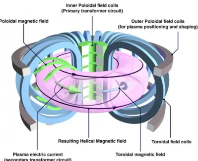
The second, named “magnetically confined fusion”, uses a magnetic field to maintain the hot fuel “detached” from the wall. The plasma ions and electrons are trapped by the magnetic field, which prevents the transversal movements; however, charged particles can move freely along the parallel direction. If designed in such way to form nested magnetic flux surfaces, the magnetic field acts as a special container, preventing the movement of the charged particles from hitting to the surrounding material walls. Among the various magnetically confined configurations, the ''tokamak'' is able to provide the best performance (see Fig. 1).
Figure 1. The tokamak: magnetic field coils and the resulting field able to confine the plasma.
12
3. Power exhaust issues in the fusion roadmap
In 2012 EFDA (European Fusion Development Agreement) published “Fusion Electricity – A roadmap to the realization of fusion energy” [3] which sets out a strategic vision toward the generation of electrical power by a Demonstration Fusion Power Plant (DEMO), around 2050.
The roadmap elaborates 8 critical strategic missions to tackle the main challenges in achieving this ambitious goal. In particular, two Work Packages have been launched as part of the mission n. 2 (“Heat-exhaust
system”) of the Road Map with the aim of carrying out alternative solutions
to the problem of disposing the heat load:
Assessment of alternative divertor geometries and liquid metals PFCs (Plasma Facing Components);
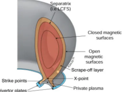
Definition and Design of the Divertor Tokamak Test (DTT) Facility. The confinement in a tokamak reactor [5] is the result of magnetic field lines forming a set of closed, nested magnetic surfaces. At the edge of the plasma, a thin (few centimeters) region with open field lines appears (Scrape-Off Layer, SOL) through which, charged particles (and the related energy) flowing out from the core plasma are directed to the divertor plates towards the separatrix (the last closed magnetic surface).
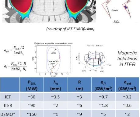
The heat flux parallel to the magnetic field, in the SOL region of ITER and DEMO, is expected to be even higher than that on the sun’s surface (see Figs. 2-4).
Figure 2: Plasma edge: geometry of the Scrape-Off Layer (SOL) and of the divertor
13
(courtesy of JET-EUROfusion)
Figure 3. Divertor heat exhaust challenge in a tokamak: PSOL is the total power flowing in the SOL channel, q is the decay length of the heat flow at the outboard
midplane, R is the major radius, q// is the heat flow parallel to the magnetic field, qpol is the poloidal component of the heath flow.
14
Figure 4. How to cope with large values of the power flux on the divertor: geometry helps, but by itself is not sufficient to handle a heat flux, expected to be higher than
that on the sun surface. Extreme conditions:
in nucleus: T > 100 M °K
in the SOL: q// > 1 GW/m2
The geometry reduces it by a factor of 30:
B toroidal >> B poloidal
Expansion of the flux on divertor
Plate inclination
... but the heat flow on the plates is still higher than the present current technological limits (about 10 MW/m2)
15
The strategy to face with the problem of thermal loads on the divertor in DEMO and, in general, in future reactors, relies upon several factors:
development of plasma facing components able to cope with very large power fluxes (>5 MW/m2) based on materials of reactor interest;
selection of the divertor geometry and of the magnetic flux map able to reduce the normal heat flux on the target, and therefore able to distribute the heat over a larger surface;
removal of plasma energy before it reaches the target, via impurity radiation; this goal is pursued by increasing edge plasma density and injecting impurities (other substances than products and reagents) in the SOL region, so the fraction of the heating power impinging on the divertor is reduced up to a level compatible with the present available technology (about 10 MW/m2);
recycling of the particles released by the wall and increase of the density close to the plates, resulting in a “detachment” from the wall of the plasma (the temperature drops below the ionization threshold, the particles become neutral and are not any more constrained by the magnetic field; consequently, no direct energy flow affects the divertor plates).
Any proposed strategy for the solution of thermal loads problem must take into account that:
present experiments where “detached” plasma conditions are carried out, are characterized by conditions of the SOL region very different from those expected in the ITER and DEMO reactors;
simulations with the available physics models for the study of SOL are presently not sufficiently reliable;
stability of the detachment front has yet to be experimentally assessed for ITER and DEMO conditions;
various problems might arise related to integration of this solution with the plasma core and the other reactor subsystems, e.g.:
- impurity contamination of the core with consequent reduction in the efficiency of the confinement and in the general performance of the reactor;
16
- compatibility of bulk plasma with the very high requested radiation fraction (> 90%);
- compatibility with pumping of the particles; - monitoring of erosion, temperature, etc.
Moreover, a number of nuclear aspects must be taken into account, restricting the use of certain materials (i.e. requirements in terms of life expectancy of reactor components, the need of limiting the temperature in the divertor region to take vanishing the erosion rate, etc…).
For these important reasons, specific programs targeted to the definition and design of the DTT (Divertor Tokamak Test facility) has been launched. This new tokamak facility is called upon to undertake scale experiments aimed to look for alternative solutions to the divertor, able to be integrated effectively with the specific physical condition and technology solutions provided in DEMO.
17
4. Role and objectives
The role of DTT project in the frame of European fusion research
The development of a reliable solution for the power and particle exhaust in a fusion reactor is recognized as one of the major challenges towards the realization of a fusion power plant [3].
The solution to adopt a conventional divertor (which will be tested in ITER) may not be suitable for extrapolation to DEMO. In order to mitigate the risk, alternative solutions must be developed.
While several alternatives, such as the cooled liquid Li limiter in FTU [6], the Super-X divertor in MAST-U [7] or the Snowflake divertor in TCV [8] are being investigated in presently operating tokamaks, the extrapolation from present devices to DEMO is considered not reliable [3].
DTT project is part of the general European programme in fusion research, which, actually, includes many other R&D issues (plasma experiments, modeling tools, technological developments for liquid divertors, etc…). The specific role of the DTT facility is to bridge the gap between today's proof-of-principle experiments and the DEMO reactor. DTT should, in particular, have the capability to bring such solutions to a sufficient level of maturity and integration from both physics and technology points of view.
The main objectives of the project DTT
The DTT facility will be able to test the physical and technological feasibility of various alternative divertor concepts that can confidently be extrapolated to DEMO. In this way, it will possible to integrate the knowledge about the concepts of a number of divertor presently in testing operation on existing machines, with the implementation requirements of DEMO.
The main objectives of DTT, as reported in a number of official European documents [3], [9], can be summarized as follows:
demonstrate that the heat exhaust system proposed for DEMO is able to withstand the strong thermal load acting if the fraction of radiated power turns out to be lower than expected;
improve the experimental knowledge in the heat exhaust scientific area that cannot be addressed by present devices;
18
demonstrate that the possible divertor solutions (e.g., advanced divertor configurations or liquid metals) can be integrated in the DEMO device.
In particular, it will be possible to assess whether:
the alternative divertor magnetic configurations are viable in terms of the exhaust problems as well as of the plasma bulk performances;
the alternative divertor magnetic configurations are viable in terms of poloidal coils constraint (i.e., currents, forces, …);
the various possible divertor concepts are compatible with the technological constraints of DEMO;
the divertors based on the use of liquid metals are compatible with the characteristics of the edge of a thermonuclear plasma;
19
5. DTT Proposal
Motivation and context of DTT proposal
EUROfusion, the European Consortium for the Development of Fusion Energy, manages the European fusion research activities on behalf of EURATOM. A significant part of the work programme of EUROfusion is devoted to power exhaust issues.
In the General Assembly of October 2017, EUROfusion acknowledged that the DTT proposal may provide important elements for finding solutions to the plasma exhaust problem, a potential crucial issue for DEMO, delivering information in operational ranges or configurations that are not accessible for the present devices or JT-60SA. In the same meeting, the General Assembly approved the principle of involvement of EUROfusion in the DTT facility around 2022-23, within a ceiling of 60 M€. In the General Assembly of April 2018, EUROfusion decided that 60 M€ should be earmarked for DTT in FP9, delaying the decision on the most appropriate involvement of EUROfusion around 2022-2023, when EUROfusion will be able to propose a divertor to be tested or the DTT plant will be at a stage with a low risk to non-completion.
Italy plays a significant role in international nuclear fusion research. Its credibility has been more and more strengthened thanks to coordinated efforts among universities, research institutions and industries, focused on innovative aspects; this cooperation has resulted in a virtuous circle that can contribute greatly to the development of the nation.
Italian fusion research is carried out under the aegis of MISE (Ministero
dello Sviluppo Economico - Ministry of Economic Development) and MIUR
(Ministero dell’Istruzione, Università e Ricerca - Ministry of Education, University and Research).
The research institutions that mainly contribute to fusion research are ENEA in Frascati, Consorzio RFX in Padua, Istituto di Fisica del Plasma del CNR in Milan, Consorzio CREATE in Naples, which coordinates the activities of several Universities in Southern Italy (including Università di Napoli Federico II, Università della Campania “L. Vanvitelli”, Università di Cassino and Lazio Meridionale), INFN with its labs in Legnaro, together with the important contributions of a number of other Italian Universities (Politecnici di Torino and Milano, Università di Milano Bicocca, Roma
20
“Sapienza”, Roma “Tor Vergata” e Roma Tre; Cagliari, Catania, Palermo, Pisa and Tuscia). The research groups operating in such institutions have cooperated for many years as part of the EURATOM-ENEA Association and EFDA. Since 2014, the collaboration takes place within the EUROfusion Consortium Agreement.
From the experimental point of view, it is to note the significant results achieved both in Frascati by the FTU Tokamak (born as an upgrade of the FT tokamak, which held the world record of the fusion performance parameter for years, and now is one of the few large facility for liquid lithium plasma facing components) and Padua with RFX-mod (the unique device able to explore, thanks to a sophisticated magnetic feedback system, the Reversed Field Pinch configurations at plasma currents up to 2MA).
Italian researchers also gave a significant contribution to the design and experimental operation of JET in Culham and are significantly contributing, since its starting, to the design and construction of ITER.
Italy is also engaged in the construction, in Padua, of an experimental apparatus, in 1:1 scale, for the injectors of neutrals in ITER. Italian researchers, meanwhile, play a key role in the European “Fusion Road Map”, leading several projects (Tasks and Work Packages) in the Horizon 2020 Work programme.
Finally, it should be pointed the high level of integration between national laboratories and the Italian industry, thanks to which a large part of the industrial contracts (around 60%) for the construction of ITER have been auctioned to the Italian companies.
Given the extent and incisiveness of fusion research in Italy and, in addition, taking into account that the removal of heat is one of the most important challenges for the construction of a magnetic confinement fusion reactor, the Italian Government proposed to allocate specific funds for the construction of an experiment dedicated to these problems. The DTT project has been proposed in 2015 by about one hundred scientists from several Italian institutions (ENEA and its Third Parties), with the support of two EU labs (KIT, Germany; IPPLM, Poland), and the collaboration of scientists from various international labs (including CEA-IRFM, France; CRPP-EFPL, Switzerland; FOM-DIFFER, the Netherlands; IPPLM, Poland). The results were collected in [1-2] and are to be presented
21
in DTT Interim Design Report, i.e. the updated version of the “Blue Book”, which will be shortly available in [1].
The relevance of the DTT project is as greater as closer it approaches to parameters and dimensions of DEMO. However, the size and the consequent construction of the project must be, in any case, compatible with the time constraints of the Road Map and the limits of financial resources. This document shows that DTT can achieve its goals with a budget of 500 M€. The project is funded by 60 M€ from EUROfusion, while another 80 M€ will come from the Italian government. The Lazio regional government will supply 25 M€, while China will provide 30 M€ and ENEA partners another 50 M€. The remaining 250 M€ will come from the European Investment Bank via a loan.
DTT parameters
Aim of DTT is to be a reduced size model of DEMO, able to study the problems of the “Scrape Off Layer” (SOL): to this spirit, every design choice has been conformed.
A machine with a plasma major radius of 2.10 m is able to ensure a region of the divertor sufficiently broad to allow the testing of different magnetic configurations and various materials, including metals liquids.
The relatively high toroidal field (BT=6T) will give the possibility to achieve plasma performances (mainly measured by the ratio between power and major radius of about 15 MW/m), not far from those in DEMO.
After the publication of the special issue of Fusion Engineering Design in November 2017 [2], the DTT Team has continued its activity to deepen and refine the project, also in the light of some suggestions of EUROfusion, as well as to start the technical and organizational steps toward realization. The main topics addressed in this review activity include:
Site selection: in April 2018 the final decision was to allocate a machine at the ENEA Research Center in Frascati (Rome);
Cost revision: in March 2018 a Cost Revision Committee has been appointed to assess the construction costs and give robustness to the economic analysis of the project;
22
Symmetrization: the DTT geometry is now up-down symmetric, so as to allow the introduction of an additional divertor and the realization of double-null configurations;
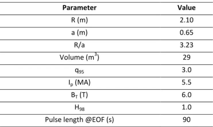
Parameter assessment (Table I): the revision process led to a slight reduction of the major and minor radius (2.10 m and 0.65 m, respectively) and plasma current (5.5 MA) leaving the magnetic field unaltered (6.0 T);
Additional review elements: a careful analysis was made taking into nuclear, mechanical, thermal, and MHD issues, leading to a revision of the main components and the various contributions to the additional heating; the maximum DD neutron yield estimated in H-mode high performance operations is 1.01017 n/s with 1.01015 n/s DT neutrons (i.e. 1%) from triton burn-up, which makes remote handling needed also in the first phase of operation;
Management organization: a dedicated consortium will be founded in 2018 so as to deal with the complex challenges of DTT construction and operation; meanwhile, an Interim Executive Board and an Interim Project Committee have been established for the general management of the project and the coordination of the various activities, respectively;
DTT Interim Design Report: an updated version of the “Blue Book” is in preparation and will be shortly available in [1].
Table I Main DTT parameters Parameter Value R (m) 2.10 a (m) 0.65 R/a 3.23 Volume (m3) 29 q95 3.0 Ip (MA) 5.5 BT (T) 6.0 H98 1.0
23
6. Scientific program
The scientific programme is described in [1-2] and in Chapter 3 of the DTT Interim Design Report, i.e. the updated version of the “Blue Book” which will be shortly available in [1].
A first phase will be aimed at the realization and installation of the various components of the machine. In a subsequent phase about a year and a half long, the machine will reach the operative capability in modality robust H-mode (i.e. operating regimes characterized by configurations of single-null divertor type, top performance and with all the additional power installed).
The next phases will be reserved to test a number of alternative divertor solutions, including new magnetic configurations and innovative technologies in the liquid metal.
DTT will be equipped with a set of external poloidal coils able to guarantee a wide range of different magnetic configurations, including XD configurations [10], Snowflakes configurations (SF) [11] and double-null point (Fig. 5).
The system also includes a number of small poloidal magnetic coils internal to the vacuum chamber, which, among other things, allow to modify locally the magnetic configurations in the divertor area.
A large space is allocated at the bottom of the machine to allow an easy installation of a divertor realized by using liquid metal technology [12]. The up-down symmetric poloidal system is designed to have also plasmas with double null configurations.
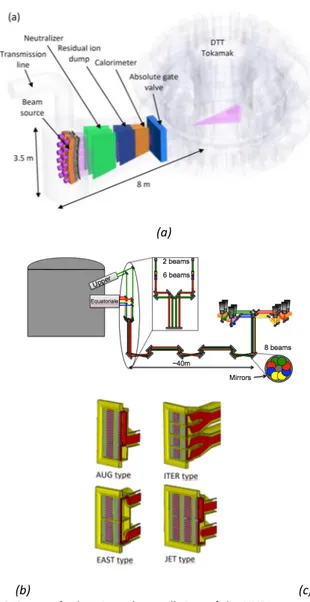
All the external coils (including the toroidal one) are designed by using superconductor technology; in this way discharges lasting around 100s are allowed, only limited by the plasma resistive flux consumption if assuming no external current drive. The heating system is based on a set of combined different technologies; a possible solution may provide a total of 45 MW including 2030 MW ECRH (Electron Cyclotron Radiofrequency Heating) at 170 GHz, 310 MW ICRH (Ion Cyclotron Radiofrequency Heating) at 60-90 MHz; 7.515MW NNBI (Negative Neutral Beam Injection). The final decision will be taken in a later stage. Figure 6 shows the overall view of the NNBI system (based on 350-400 keV beam energy), the transmission lines of the ECRH system (to be realized in vacuum or
24
open air), and the different ICRH antenna concepts presently considered in the design, for which the final decision will be taken on the basis of the results of a set of experiments to be carried out in EAST.
Figure 5: Conventional and alternative magnetic configurations that can be realized by the DTT poloidal field system.
The ambitious program of DTT is spread over a period of several years. During the initial plasma operations 3 MW of ICRH, 14.5 MW of ECRH, and 7.5 MW of NNBI will be available. Additional power, up to a total of 45 MW, will be afterwards installed, taking also advantage of actual technologies available in the various phases of the project. The project foresees the testing of different divertor concepts looking for the best
25
magnetic configuration and the optimized divertor design; as an additional goal, also the solution based on the technology of liquid metal will be optimized.
(a)
(b) (c)
Figure 6: System for heating: a) overall view of the NNBI system; b) ECRH transmission lines; c) ICRH concepts considered for DTT.
26
7.
Physics basis of the project and its operational
capabilities
An artist's view of the DTT facility is reported in Fig. 7.
All the plasma configurations (including standard single null and advanced configurations) satisfy the following constraints:
distance not less than 30 mm between the plasma last closed surface and the first wall, in order to minimize the interaction between the plasma and the vacuum chamber; as a matter of fact, the power decay length at 5.5 MA is about 2 mm at the outboard midplane;
plasma shape parameters similar to those of the present design of DEMO: R/a≈3.23, k≈1.7, <δ>≈0.35;
pulse lasting about 100 s (total available flux more than 42 Vs, Central Solenoid swing more than 32 Vs).
These needs have suggested the use of superconducting windings; in particular, the magnetic system includes:
Toroidal Field (TF) magnetic system: 18 NbSn3 TF coils; Bpeak: 11.8 T,
Bplasma: 6.0 T, 63 MAt;
Central Solenoid (CS): 6 independent CS coils would in layers: Bpeak;
13.8 T; available poloidal flux: 16.2 Vs;
Poloidal Field (PF) magnetic system: 6 independent NbTi PF coils; Bpeak: 6.0 T.
The PF system also includes eight copper in-vessel coils; in particular:
two in-vessel copper coils for radial and vertical stabilization and control;
four in-vessel copper coils for magnetic control of SOL and strike point sweeping.
The magnet system is conceived so as to be compatible with a future upgrade, consisting in the insertion of an additional coil inside the original CS bore at a later stage (Fig. 8). This additional coil should operate at very high field (more than 15 T) and should be made using a HTS (high temperature superconductor) like for instance YBCO tapes. This insert would not only give an increase (about 15%) of the available flux and the pulse duration, but would also achieve the technological target of demonstrating the feasibility of fusion using HTS.
27 To pursue the aims of the program, particular attention has been devoted to the diagnostics and control issues, especially those relevant for plasma control in the divertor region, anyway having in mind the requirement of a strong compatibility with the operating conditions in DEMO. Figure 7: Artist's view of the DTT device. Figure 8: The DTT superconducting magnet system. The design of the Vacuum Vessel (VV) includes a D‐shaped double wall of AISI 316‐L(N). The 18 sectors are joined by welding. The thickness of each shell is 15 mm while the 5 ports per sector have a 25 mm thick single shell (Fig. 9).
28
Figure 9: A 60 deg DTT vacuum vessel sector.
The first wall consists of a bundle of tubes armored with plasma‐sprayed tungsten. The layer of tungsten is 5 mm thick; the bundle of cooling copper tubes and the support is provided by a back plate of SS316LN steel have a total thickness of 45 mm.
The main goal of the DTT project is to test several divertor concepts and configurations. Therefore, the design of the VV, the ports and the additional heating system takes into account the constraints related to the testing of conventional and liquid metal divertors.
In case EUROfusion is not ready with a specific proposal in 2022‐2023, the “first day” design includes a tungsten divertor, realized with W‐shaped modules, distributed along the VV; the design is fully compatible with advanced magnetic configurations (Fig. 10).
(a) (b)
Figure 10: a) A possible tungsten divertor, compatible with both the SN and SF configurations; b) Liquid lithium limiter installed FTU: a good starting point for
29
8. Costs and schedule
The facility needs to be ready by 2025, in order to be able to bring at least one alternative divertor strategy to a suitable level of maturity around 2030 for a positive decision on DEMO. The nominal duration of the construction of DTT from the “green light” to the beginning of the initial operational phase is expected in about seven years. Consistently with EUROfusion road map, a reasonable time planning implies that the first tenders for the supply of DTT components could be issued by end of 2018. The realization of the DTT project is a top priority for the fusion European community, since it represents a crucial step towards the realization of a DEMO reactor.
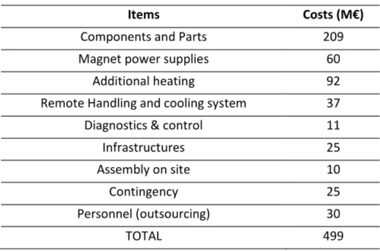
The exploitation of DTT scientific program has been included in the European Road Map towards fusion energy. The realization of the facility has been included in the list of projects submitted for gaining access to the funding of 50%, out of the whole 500 million Euro investment, as part of the “Program Juncker” (EFSI: European Fund for Strategic Investments). The amount claimed is consistent with the table of costs listed in Tab. II, according to the evaluation reported in the “Blue Book” and in the Special Issue of Fusion Engineering and Design on DTT [2].
Table II
DTT Cost Breakdown (Summary)
Items Costs (M€)
Components and Parts 209
Magnet power supplies 60
Additional heating 92
Remote Handling and cooling system 37 Diagnostics & control 11
Infrastructures 25
Assembly on site 10
Contingency 25
Personnel (outsourcing) 30
30
9. Site assessment and socio-economic Impacts
The choice of the site took into account the mission of DTT as “European facility”. In this perspective, significant elements for the selection of the site have been the accessibility and the scientific attractiveness for staff (scientists and engineers) that, coming from many European countries and beyond, will carry out the construction and promote experimentation. The site, selected as a result of a Call for Interest addressed to the Italian Regions, is the ENEA Research Center in Frascati (Rome, Italy). The selected site is, indeed, compliant with the whole specifications of the location. Frascati is also a fairly attractive site from cultural and logistic standpoints.
The realization of the new infrastructure will be beneficial as the following aspects are concerned:
socio-economic aspects of the hosting territory;
the technological and scientific challenges for the EU fusion community, which will have the occasion to gain experience and growth young generation by building and operating a DEMO-relevant machine in the next decades.
That comes out from a well consolidated experience in building and running large research infrastructures showing how the realization of big international research projects has a large and positive impact on the socio-economic hosting territory; consider, for example, the impact of JET and, more recently, that of the design and construction of ITER. Construction of major research infrastructure provides an opportunity to use the increase in knowledge as a driving force for the development of synergistic technical and economic aspects of the surrounding area. On the basis of this experience, it is possible to provide a number of positive elements expected for the site area, during both the construction and the operations phases. The list of main effects includes: i) occupational impact; ii) technology transfer to the industry; iii) positive economic impact on businesses and, in general, on the level of welfare of the population; iv) the transfer of knowledge and innovation capacity in favor of scientific laboratories and universities in the area.
31
10. References
[1] http://www.dtt-project.enea.it/
[2] Special Section: DTT, Fusion Engineering and Design, Vol. 122, 2017, pp. 253-294 and e1-e25
[3] EFDA, Fusion Electricity: A roadmap to the realisation of fusion energy, November 2012,
[https://www.euro-fusion.org/wpcms/wp-content/uploads/2013/01/JG12.356-web.pdf] [4] http://www.iter.org/
[5] Wesson J., “Tokamak”, Oxford University Press 2011 – 4th Edition [6] Mazzitelli G. et al., Nucl. Fusion, 51, 073006, 2011
[7] http://www.ccfe.ac.uk/mast_upgrade_project.aspx
[8] Reimerdes H., et al., Plasma Phys. Control. Fusion, 55, 124027, 2013 [9] Report of the STAC Ad Hoc Group on 'A strategy to address exhaust issues in
the EU Fusion programme Phase I', Final version, 10.7.201 [10] Kotschenreuther M., et al., Phys. Plasmas, 20, 102507, 2013 [11] Ryutov D.D., Phys. Plasmas, 14, 064502, 2007
[12] M. Ono et al., Nucl. Fusion, 52, 037001, 2012, doi: 10.1088/0029-5515/52/3/037001
ENEA
www.enea.it