Qualifica di codici di calcolo dedicati alle
analisi di sistemi avanzati quando
applicati nella simulazione di impianti a
metallo liquido
A Del Nevo, C. Venturi, E. Martelli, D. Rozzia, F. Castiglia,
M. Giardina, F. Mascari, M.L. Richiusa, G. Vella
Report RdS/2013/025
Agenzia nazionale per le nuove tecnologie,
QUALIFICA DI CODICI DI CALCOLO DEDICATI ALLE ANALISI DI SISTEMA AVANZATI QUANDO APPLICATI NELLA SIMULAZIONE DI IMPIANTI A METALLO LIQUIDO
A. Del Nevo, C. Venturi, E. Martelli, D. Rozzia (ENEA), F. Castiglia, M. Giardina, F. Mascari, M.L. Richiusa, G. Vella (UNIPA)
Settembre 2013
Report Ricerca di Sistema Elettrico
Accordo di Programma Ministero dello Sviluppo Economico -‐ ENEA Piano Annuale di Realizzazione 2012
Area: Produzione di energia elettrica e protezione dell'ambiente
Progetto: Sviluppo competenze scientifiche nel campo della sicurezza nucleare e collaborazione ai programmi internazionali per il nucleare di IV Generazione
Obiettivo: Sviluppo competenze scientifiche nel campo della sicurezza nucleare Responsabile del Progetto: Mariano Tarantino, ENEA
Il presente documento descrive le attività di ricerca svolte all’interno dell’Accordo di collaborazione “Sviluppo competenze scientifiche nel campo della sicurezza nucleare e collaborazione ai programmi internazionali per il nucleare di IV generazione” Responsabile scientifico ENEA: Mariano Tarantino
S
UMMARY
The report is a contribution on activities related to the development and the qualification of thermal-hydraulic system codes and of methods for safety analyses of liquid metals Gen. IV reactors. The report is divided into two parts.
The former (A) presents the development of two RELAP5-3D© nodaliztions of pool type sodium cooled fast reactors. The CP-ESFR nodalization is rather simple and fast running, and will be finalized using the neutronic data calculated in the framework of the same task LP2 A3. The EBR-II is detailed. Indeed, it models the overall pool system and the reactor zone with a 3D component, and the driver core fuel assemblies, fed by the high flow line, one by one. This is developed and set-up in the framework of IAEA coordinated research project (CRP) on EBR-II Shutdown Heat Removal Tests (SHRT). The report describes the framework of the activities, the nodalization and the first steps of qualification.
The second part (B) deals with studies on the applicability of current thermal-hydraulic system codes when applied to safety analyses of pool type Gen. IV fast reactors, cooled with liquid metals (i.e. ELSY o ALFRED). The study is based on the following rationale: 1) identification of thermal-hydraulic phenomena relevant for the safety; 2) identification of the main models and correlations relevant for the code simulation; 3) a qualitative evaluation of the reliability and limitations of those models and correlations; 4) the identification of possible model improvements.
L
IST OF CONTENTS
SUMMARY ... 3
PART
A:
DEVELOPMENT
AND
SETUP
OF
RELAP5-3D©
NODALIZATIONS
OF
LIQUID
METAL
POOL
FAST
REACTORS ... 5
1
DEVELOPMENT
AND
SET
UP
OF
CP-ESFR
NODALIZATION
BY
RELAP5-3D©
V4.0.3
CODE ... 8
2
DEVELOPMENT
AND
SET
UP
OF
EBR-II
NODALIZATION
BY
RELAP5-3D©V4.0.3
CODE ... 27
PART
B:
REVIEWING
THE
TH-SYS
CODES
CAPABILITIES
AND
LIMITATIONS
IN
SAFETY
ANALYSES
OF
GEN.
IV
POOL
TYPE
LIQUID
METAL
FAST
REACTOR ... 48
3
QUALIFICA
DI
CODICI
DI
CALCOLO
DEDICATI
ALLE
ANALISI
DI
SISTEMA
AVANZATI
QUANDO
APPLICATI
NELLA
SIMULAZIONE
DI
IMPIANTI
A
METALLO
LIQUIDO ... 49
4
PRINCIPALI
MODELLI
E
CORRELAZIONI
DISPONIBILI
IN
LETTERATURA
PER
L’ANALISI
DI
TRANSITORI
IN
REATTORI
DI
IV
GENERAZIONE
REFRIGERATI
A
METALLO
LIQUIDO
E
POSSIBILI
APPLICAZIONI
E
IMPLEMENTAZIONI
IN
CODICI
DI
PART
A:
DEVELOPMENT
AND
SETUP
OF
RELAP5-3D©
L
IST OF FIGURES
Fig. 1 – CP-ESFR: 3D view of the pool and internals. ... 14
Fig. 2 – CP-ESFR: radial cross-section of the SFR core with oxide fuel ... 14
Fig. 3 – CP-ESFR: Inner and outer sub assembly regions ... 15
Fig. 4 – CP-ESFR: hexagonal wrapper tube and fuel pin ... 15
Fig. 5 – CP-ESFR: diagrid strongback and pump radial and axial sections ... 16
Fig. 6 – CP-ESFR: flow sodium from strongback to diagrid ... 16
Fig. 7 – CP-ESFR: Above Core Structure ... 17
Fig. 8 – CP-ESFR: Pump connection to stongback by sphere ... 17
Fig. 9 – CP-ESFR: IHX ... 18
Fig. 10 – CP-ESFR: Weir system ... 19
Fig. 11 – CP-ESFR: RELAP5-3D© nodalization sketch of primary system ... 23
Fig. 12 – CP-ESFR fuel assembly performances: sodium temperature vs. power at core outlet ... 24
Fig. 13 – CP-ESFR fuel assembly performances: cladding temperature vs. power at core outlet ... 25
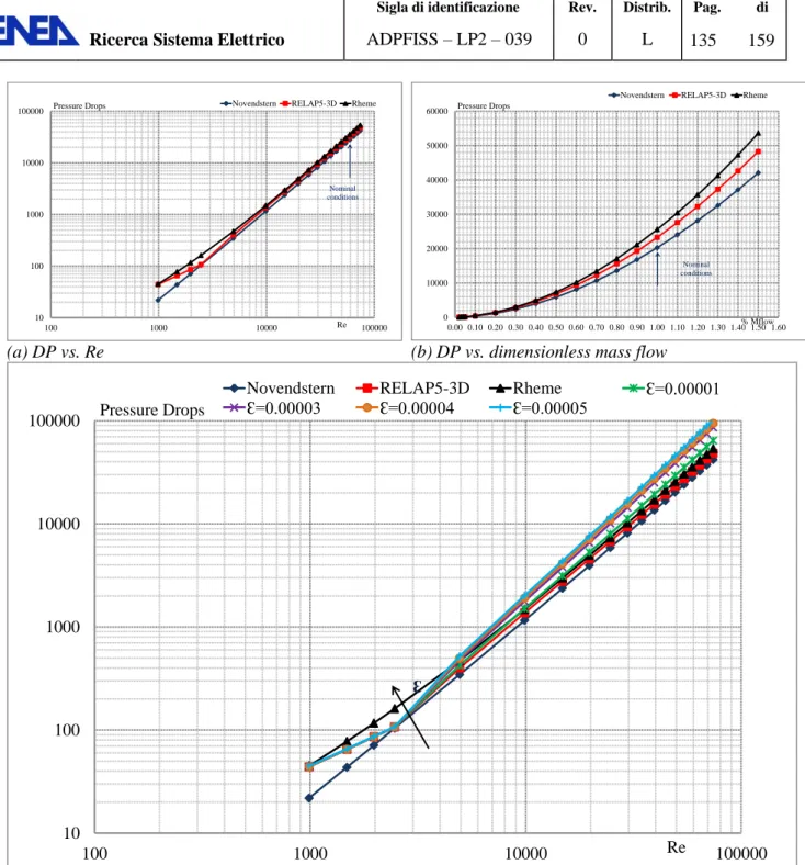
Fig. 14 – CP-ESFR fuel assembly performances: friction losses in wire wrapped fuel assembly vs. experimental based empirical correlations. ... 25
Fig. 15 - EBR-II Primary Tank Sodium Flow Paths. ... 33
Fig. 16 - EBR-II Plant Schematic. ... 33
Fig. 17 - EBR-II SHRT-17 Core Loading Pattern (First 8 Rows) ... 34
Fig. 18 - EBR-II Core Layout ... 34
Fig. 19 - EBR-II MARK-II AI Subassembly Configuration. ... 35
Fig. 20 - EBR-II Primary Tank Layout. ... 35
Fig. 21 - EBR-II Primary Tank Vessel. ... 36
Fig. 22 - EBR-II Reactor Vessel. ... 36
Fig. 23 – EBR-II High and Low Pressure Inlet Plena. ... 37
Fig. 24 - EBR-II Intermediate Heat Exchanger... 37
Fig. 25 - EBR-II nodalization: schematizzation of 3D component in the plane R, Z. ... 39
Fig. 26 - EBR-II nodalization: schematization of the 3D component with the 1D componenet connections.. 40
Fig. 27 - EBR-II nodalization: schematization from pumps connctions to high and low pressure reactor inlet plena. ... 40
Fig. 28 - EBR-II nodalization: schematization of Z pipe, IHE primary and secondary sides. ... 41
Fig. 29 – EBR-II nodalization: MARK-IIA fuel assembly ... 41
Fig. 30 – EBR-II nodalization. MARK II dynamic pressure drop in wire wrapped fuel bundle ... 44
Fig. 31 – EBR-II nodalization. MARK II heat exchange tests: low mass flow rate tests ... 45
L
IST OF TABLES
Tab. 1 – CP-ESFR: plant characteristics. ... 13
Tab. 2 – CP-ESFR: fuel pin characteristics ... 13
Tab. 3 – CP-ESFR, : RELAP5-3D© pump model, single phase homologous courves. ... 22
Tab. 4 – CP-ESFR, : RELAP5-3D© pump model, coastdown vs time. ... 23
Tab. 5 – CP-ESFR nodalization. Mass flow distribution in primary system: design data vs. code results... 24
Tab. 6 - EBR-II design parameters (nominal) of subassembly fuel elements. ... 32
Tab. 7 - EBR-II design parameters (nominanl) for subassembly structure. ... 32
Tab. 8 – EBR-II nodalization. MARK II pressure drop test: initial conditions ... 43
Tab. 9 – EBR-II nodalization. MARK II pressure drop test: RELAP5-3D results ... 43
Tab. 10 – EBR-II nodalization. MARK II heat exchange tests: initial conditions ... 43
Tab. 11 – EBR-II nodalization: SHRT-17 boundary conditions: fuel assembly mass flow distribution at steady state ... 46
1 D
EVELOPMENT AND SET UP OFCP-ESFR
NODALIZATION BYRELAP5-3D©
V4.0.3
CODE1.1 Framework
The development of the CP-ESFR has a twofold objective: 1) the set up and application of a chain of codes for supporting the design and safety analysis of liquid metals pool types Gen. IV reactors; 2) the assessment of core thermal-hydraulic parameters (i.e. cladding temperature, coolant temperature at core outlet and fuel centerline temperatures) of two different fuel design (i.e pelletized and sphere-packed). The activity is connected with the EC project PELGRIMM.
1.1.1 Description of CP-ESFR
CP ESFR is a large integrated Collaborative Project on European Sodium Fast Reactor realized under the ages of the EURATOM 7th Framework Programme, which merges the contribution of 25 European partners[1]. The ESFR plant design is based on an industrial sodium cooled pool reactor of 1500 MWe with a plant‟s efficiency of 42%.
The CP-ESFR (Fig. 1) designed comprises the core, the above core structure, the Fuel Handling System (FHS), three mechanical primary pump, six secondary loops, each had one Intermediate Heat Exchangers (IHX) on the reactor side and six modular sodium/water Steam Generators (SG). In addiction there are six Deacay Heat Exchangers (DHX) connected to six Direct Reactor Cooling loops (DRC) to ensure decay heat removal of the reactor when it is shut down. In Fig. 1 is represented a plant layout for twinned reactors and in Fig. 1 a 3D view of the CP-ESFR pool with theirs components.
The project design was made base on specified objectives: - Simplification of structure
- Improved In Service Inspection and Repair
- Improved manufacturing conditions for cost reduction and increased quality - Reduction of risks related to sodium fires and to the water/sodium reaction - Improved robustness against external hazards.
The main characteristics of CP-ESFR are summarized in the Tab. 1.
The oxide core consists of 225 inner and 228 outer fuel sub assembly (Fig. 2). Three rows of reflector sub-assemblies, not reported in the figure, can be used to place one fertile or MA fuel assembly and two additional rows of steel blocks. The “control” rod system is composed by 9 DSD (Diverse Shutdown Device) assemblies and 24 CSD (Control and Shutdown Device) assemblies.
The inner and outer sub-assembly, in Fig. 3, consist of a hexagonal wrapper tube made of ferritic martensitic steel (EM10). Within, it is located a fuel bundle and ,a reflector and absorber layers. The fuel bundle consists of 271 pins (see Fig. 4). The clad is fabricated in ODS steel with outer diameter of 10.73 mm and 0.5 mm of thickness. Pins are placed in a triangular arrangement with helical wire wrap spacer. The overall length of the fuel pin bundle is 2.363 meter. The active core region is 1 meter long. The uranium oxide fuel pellets have a outside diameter equal to 9.43 mm. The gap has a thickness 0.15 mm filled with helium.
A fertile blanket region (300 mm) that contains only depleted uranium oxide, a lower gas plenum filled by helium and a plug with ODS steel pellets are placed below the active core region. The fuel rod has an upper gas plenum and an upper plug with the same characteristics.
Each sub-assembly fits in the diagrid support sub-assembly plate by the foot sub-assembly for a length of 600 mm. The inner and outer fuel sub-assembly have the same axial sub-assembly structure but they differs in Pu mass content. 14.05% for inner fuel region and 16.35% for the outer.
Over fuel pin bundle there is a sodium region, then the absorber and reflector regions. These regions have 19 pins in the same configuration of fuel region but without the helical wire wrap spacer. The external radius of each pin is 40 mm. In the absorber and reflector region, clads are made in EM10 material (1 mm of thick) and pellets are made in B4C and steel F17 respectively. Between clad and pellet there is a gap of 1 mm.
Outside the core, three rings of reflectors are installed. Only 84 sub-assemblies are cooled. The central assembly of the core is a reflector.
Reflector pins placed in the inner region have the same characteristics of the UPS region, described above. The core and the neutron shielding are fixed on a diagrid, which is supported on the strongback. The strongback is laid on the main vessel bottom and transfers the total core weight.
The diagrid is a stainless steel cylindrical structure with a diameter of 7.4 m. It contains a large number of vertical circular shroud tubes where the core subassemblies are inserted. These shroud tubes provide the positioning and support for the subassemblies and allow the sodium feed from the strongback through holes. The detailed flow arrangements are such that the hydraulic forces acting on the subassemblies serve to hold them down in the diagrid. This structure is entirely welded. The absence of bolts removes any risk of loose parts inside the primary circuit. The diagrid structure needs high stability (thermal and mechanical) to avoid changes in core geometry that may cause excursions of reactivity.
The strongback is a stainless steel pressurized (5 bar) box-type structure comprising two circular plates linked by welded webs. It is resting on the vessel bottom (no welding). A pivot centers the strongback and provides an ultimate redundant support in case of core structure collapse. It could also offer a natural path to corium. Absence of welding between strongback and vessel is favorable regarding seismic and inspectability issues.
The pump is connected to the strongback and not to the diagrid (like in Superphenix), see Fig. 5. The new design allows a shorter and more robust pipe connection, reducing the risk of a break. Sodium flows (Fig. 6) first through the strongback with a pressure of 5 bar. Then, it flows through the diagrid by means of 18 flexible sleeves (500 mm diameter ). The sleeves are welded on the lower surface of the diagrid. A share of flow sodium, 830 Kg/s, entering in diagrid through sleeves is directed to core catcher to cooling vessel. They may undergo high thermomechanical constraints during transients, and their behavior is to be considered with great care for design improvements. Monitoring is necessary to detect deterioration of the support structures.
The ACS (Above Core Structure) is a conical structure located over the core. The main functions are: 1) the support of control rod drive mechanisms and core instrumentation, and 2) the control of the primary sodium flow distribution into the hot pool to achieve the required thermal-hydraulic conditions and quality of the sodium free surface. The ACS supports the Direct Lift Charge Machine (DLCM) is installed in the center. It is used for handling of core center fuel assemblies. The ACS also provides the thermal protection of the equipment within the ACS and the SRP (Small Rotating Plug).
• The outer shell. • The baffle plate.
• The porous plate (flat plate at the base of ACS with holes for sodium flow and penetration of the shroud and instrumentation guide-tubes).
• Shroud tubes (tubes to drive absorber rods (CSD and DSD), the Direct Lift Charge Machine (DLCM), the Failed Fuel Location system (FFL), Core Thermocouples, core measuring and ISI monitoring systems).
• Instrument Guide Tubes (IGT).
• The Thermocouples and Failed Fuel Location (FFL) pipework.
• The Multiple Layer Insulation (to reduce the heat transfer to the small rotating plug, and control the axial temperature gradient in the external shell of the ACS).
The ACS extends over one row of steel reflectors and is immersed in the sodium to a height of 6 m. The environment above the sodium comprises a layer of argon, which may contain sodium vapor and aerosols and 0.85 m depth of multiplate insulation to reduce the heat transfer from the ACS to the SRP. Most of the ACS structures are immersed in the stream of sodium emerging from the core, at a temperature ranging from 560°C at the core outlet to 545°C at the sodium surface. The top part of the structure, approximately 1.160 m, however, is located in the cover gas region where the temperature ranges from 130°C at the interface between the insulation plates and the underside of the SRP, to 545°C at the sodium level. Instrumentation is routed via straight instrumentation guide tubes below the baffle plate. The tubes provide access to the core for Thermocouples (TC), Failed Fuel Location sampling systems (FFL), Fission Chambers (FC), and nucleonic instruments.
A flow baffle is incorporated to slow down the velocity of the coolant emerging from the core and to direct the flow into the hot pool, in a way that meets the thermal hydraulic objectives, such as mixing, flow and temperature distribution and hot pool surface quiescence. One of the most important problems to be solved, by the ACS, is to get a structure rigid enough to resist the core emerging flow impingement and seismic movements, and flexible enough to accommodate thermal differential stresses, due to core coolant emerging flow temperature variations and gradients. The ACS is integrated in the SRP. As such, it can only be removed as a complete unit. It takes part in the primary argon cover gas containment. It also forms a part of the primary circuit.
Three primary pumps are installed with a nominal flow mass of 6512 kg/s each. Every pump comprises a cylindrical casing and vertical shaft machine inserted into the primary circuit via a penetration in the reactor roof, on which it is mounted.
The bottom end of the pump, the outlet, is connected with a sphere to the strongback, whilst the pump suction side/inlet to the impeller communicates directly with the reactor‟s cold pool. The design has been kept as simple as possible, without valve. Pumps are located on a common pitch circle diameter and forming a parallel circuit with the same pump head and specific energy requirement.
The design (Fig. 8) includes the following main features:
• Single mixed flow impeller.
• Top inlet entry flow to the impeller.
• Subcritical hollow drive-shaft, designed to get the first critical whirling speed above the maximum operating speed with a comfortable margin.
• Synchronous motor to allow easy operation of the pump over the whole range of required speeds (with specific regulations).
The impeller is mounted on the drive shaft. A flywheel is implemented in order to extend the rundown time. The shaft is supported at the top end by a magnetic axial thrust bearing and a radial bearing.
A hydrostatic sodium radial bearing is located at the bottom of the shaft above the impeller and is fed with high pressure sodium from the outlet collecting sphere (Fig. 8).
Six IHX (intermediate heat exchange) on 600 MWth are installed in reactor vessel (Fig. 9). It is a counter flow heat exchanger with the secondary sodium flowing downwards through a central duct before turning upwards in the bottom header and flowing vertically inside the heat exchanger tubes, where it is heated by the primary sodium flowing downwards on the shell side. The IHX unit is connected physically and functionally to both the primary and secondary sodium circuits. The design requirements are:
• Maximum allowed pressure drop imposed by the primary and secondary systems (~17 kPa on the primary sodium side, ~0.1 MPa on the secondary side).
• Maximum secondary circuit pressure in case of steam generator unit design based accident (about 55 bar on the IHX in case of a Sodium/Water reaction resulting from the failure of all the tubes of a modular SG).
• The seal between the IHX and the inner vessel must accommodate thermal movements between the components and the conical part (redan). A gas seal is not recommended (risk of gas entrainment into the core).
The IHX has a valve on the primary sodium side allowing the inlet window to be closed and the secondary circuit and steam plant to be isolated from the primary circuit. The reactor might be operated with one or two IHX isolated.
The inner vessel is an axisymmetrical shell fabricated structure, comprising: conical part (redan), a cylindrical inner vessel upper skirt, a cylindrical core barrel welded on the strongback. In the conical skirt, there are a minimum set of 9 penetrations: 6 fot the IHX penetrations and 3 for primary pump penetrations.
The inner vessel separates the hot pool which contains the core subassemblies and the IHX inlets from the cold pool where are located the IHX outlets and the primary pumps inlets. It provides a leaktight barrier between the hot and cold pools and provides geometric and hydraulic guide to the pump inlets. It participates with the other internal structures in the distribution of the primary sodium flow inside the main vessel.
A conical skirt (redan) is proposed in place of the ogival skirt of EFR to simplify manufacturing. The core barrel is welded on the strongback (and not on the diagrid). As a result, the conical skirt is less sensitive to buckling by plastic ruin. It also decreases the surface subjected to the difference in pressure between collectors, and it provides a natural protection of the diagrid against hot shocks at the exit of the IHX. The inner vessel upper part is subject to high thermo mechanical constraints at the free surface (sodium at 545°C, argon at 400°C), leading to minimize thickness in that region to lower thermal fatigue. On the other hand, it must also sustain high mechanical and fluid loads during an earthquake, and its thickness must be large enough to ensure its stability.
The main vessel is fabricated in austenitic steel (316LN). It is hanged to the civil work by means of a forged piece. The upper cylindrical part is cooled by a small sodium flow taken from the cold plenum below the diagrid. An immersed weir (Fig. 10) limits the risk of gas entrainment and ensures creep and fatigue
resistance of the main vessel over 60 years. The strongback is laid on a forged structure in the vessel wall, which improves the integrity and inspectability both during manufacturing and reactor life.
The main vessel is completely surrounded by a leak tight safety vessel. A nitrogen atmosphere is maintained between the two vessels. The safety vessel may be fabricated in another grade than main vessel to avoid common mode failure. The main function of the safety vessel is to avoid core uncovering in case of a leakage of the main vessel. The interspace between the main vessel and safety vessel is large enough to accommodate a wheeled ISI vehicle for inter-vessel inspection, but small enough to ensure a sufficient sodium level in the event of a main vessel leakage – to allow decay heat removal via the normal IHX and DRC systems.
GENERAL CHARACTERISTICS PLANT
Reactor heat output 3600 MWth
Net electrical output 1500 MWe
Plant lifetime 60 years
Global efficiency 42%
Availability objective 90%
Number of IHX 6
Number of DHX 6
Number of pumps 3
Number of secondary loops 6
Number of DRC loops 6
Tab. 1 – CP-ESFR: plant characteristics.
FUEL SUB-ASSEMBLY DESIGN oxide
Sub assembly pitch [mm] 0.2108
sodium gap with inter assembly [mm] 0.0045 wrapper tube outer flat-flat width [mm] 0.2063
wrapper tube thickness [mm] 0.0045
wrapper tube material FM steel (EM10)
WIRE
wire wrap spacer diameter [mm] 0.001
wire wrap helical pitch [mm] 225
wire wrap spacer material ODS steel
FUEL PINS
number of fuel pins for sub-assembly 271
outer clad diameter [mm] 0.01073
inner clad diameter [mm] 0.00973
cladding material ODS steel
fuel pellet diameter [mm] 0.00943
fuel pellet material (U,Pu)O2
fuel average density 88% TD
O/M 1.98
Fig. 1 – CP-ESFR: 3D view of the pool and internals.
Fig. 3 – CP-ESFR: Inner and outer sub assembly regions
Fig. 5 – CP-ESFR: diagrid strongback and pump radial and axial sections
Fig. 7 – CP-ESFR: Above Core Structure
Fig. 10 – CP-ESFR: Weir system
1.2 Nodalization description
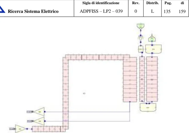
RELAP5-3D© nodalization of CP-ESF models the primary and the secondary systems. The primary system is assembled using 1D components (Fig. 11). It is divided into the following main parts:
1. the core region, 2. the hot pool region, 3. the ACS,
4. the IHX primary side, 5. the cold pool region, 6. the pump,
7. the strongback and diagrid regions, and 8. the vessel cooling bypass
The core region is divided into 8 separate PIPE components according with the following rationale. Component 100 (CV100) represents the central dummy assembly, which is a reflector. RELAP5-3D© pipe CV101 is equivalent to 3FA. These are the power peak FA, indeed the symmetry of the reactor is of 120°. According with the design of the core, the maximum power FA can be located either in the inner and in the outer zones of driver zone, depending upon the irradiation history. The 1D schematization of the nodalization neglects this difference, because in any case the hot FA are modeled separately. The inner and outer core zones are nodalized with a PIPE components equivalent to 222 and 228 FA, respectively (i.e CV 104 and CV326). The peripheral core region is modeled separating the 84 reflector subassembly channels and the 456 reflector blind channels. One PIPE component represents the CR subassemblies (CV557). The fuel assembly channels are subdivided into 25 hydraulic volumes connected to the lower volumes of the strongback. Exception is the core bypass zone fed by the top volumes modeling the strongback, which are 22 hydraulic volumes. Heat structures are implemented in the input deck, accounting for both active and passive structures. Each equivalent fuel assembly box is connected from the thermal point of view with the RELAP5-3D© component representing the core bypass (CV590).
The hot pool region is schematized with two stacks of pipes connected with cross junctions, representing the inner and the outer zones. PIPES and BRANCH components from CV630 to CV 635 model the volume between the core barrel (lower part of inner vessel) and the core region. Radial connections allow the flow between the inner part of this zone and the core bypass PIPE (above). Similar approach is used to represent the upper part, including the conical shaped zone of the inner vessel (from CV 640 to CV 652). On the top, three BRANCH components initialized with inert gas, model the reactor zone above the sodium level free surface. The passive heat structures of the hot pool region are accounted for. The overall mass of metal is
preserved and distributed along the vertical direction according with the specifications in Ref. [7]. Some of them exchange energy with other reactor zones (e.g. inner vessel heat structures is a passive structure between the hot and cold pool zone; the coolant in the ACS exchanges energy with the hot pool region through the ACS heat structure; the lower annular dead zone of the hot pool surrounding the core region exchange energy with the coolant flowing through the strongback and the diagrid). Some others are modeled as thermal inertia (i.e. coolant pump housing and upper part of the IHX).
The ACS is represented with the same rationale of the hot pool region, thus separating the inner and the outer fluid in order to allow the recirculation of coolant in the zone. The shroud tubes are modeled with two PIPE components, which represent the equivalent number of tubes in the inner and outer zones of the ACS. The tubes are hydraulically connected with their corresponding ACS zone into three places: two in the sodium zone (bottom and middle height) and one in the non-condensable zone (top). Heat exchange from shroud tubes and ACS is also modeled.
Six IHX are represented with an equivalent component. The primary side is rather simple and based on two BRANCH components for the inlet and outlet zones and a PIPE component for the tube zone. The IHX is connected upstream and downstream with the hot and cold regions, respectively The secondary system is modeled with: 2 TIME DEPENDENT VOLUME and 1 TIME DEPENDENT JUNCTION components for setting the boundary conditions (i.e. pressure at the outlet and coolant temperature and mass flow rate at the inlet); and 2 PIPES components having 26 sub-volumes each representing the descending tube and the ascending tubes. Suitable thermal coupling is implemented to calculate the heat exchange primary to secondary systems as well as the thermal losses between the IHX
The cold pool region is schematized with the same approach used in the hot pool region. The volume is divided into two concentric zones (i.e. inner and outer). The two parallel stacks of PIPE and BRANCH components is used. The hydraulic zone is extended from the bottom of the main vessel up to the top of the gas line where it is connected with the hot zone and the bypass zones through the gas plenum on the top of the vessel. The cold pool zone connects the IHX component with the suction of MCPs. The passive heat structures are modeled according with the CP-ESFR design.
The six pumps are modeled with an equivalent PUMP component of RELAP5. The main data of the pump model (i.e. the homologous curves) and the MCP coastdown versus time are reported in Tab. 3 and Tab. 4, respectively. They have been set up on the basis of the data available in Ref. [6].
The strongback and diagrid regions are represented connecting PIPE and BRANCH components according with the rationale hereafter discussed. The annular region connected with the PUMP outlet is vertically oriented. The region is connected with the diagrid zone, which is located below the core region. It is modeled separating the annular region feeding the blanket zone from the central part connected with the inner and outer driver. A connection link the top blind zone of the diagrid represented with a single BRANCH component with the core bypass. On the contrary, the FA are fed from the bottom of the diagrid zone. The second bypass is modeled connecting the central lower part of the diagrid, in downward direction, with the central part of the strongback zone (PIPE component in RELAP5). The coolant flows downward towards the vessel cooling system. The heat structures of the zone are geometrically complicate and detailed data of the geometry are not always available. However, Refs. [6] and [7] provide integral data of the metal volumes in the reactor. Therefore, passive heat structures have been implemented in RELAP5 nodalization preserving the overall heat capacity and as much as possible, the flow areas. These are uniformly distributed in the RELAP5 hydraulic regions according with the CP-ESFR design available data, if no details are available.
The vessel cooling bypass is considered in the nodalization. It connects the lower part of the vessel below the strongback with the gas zone on the top of the reactor and the cold pool. This hydraulic region is connected with the heat structure modeling the reactor primary vessel, with an adiabatic boundary condition on the external wall (i.e. left boundary condition). On the other side, the hydraulic component is connected with the hot and the cold zone of the nodalization.
The elevations of the different parts of the plant are maintained in the nodalization. A sliced approach is applied at all systems (i.e. primary and secondary systems).
The node to node ratio is kept uniform, as much as possible, with reference maximum ratio of 1.2 between adjacent sub-volumes.
The heat transfer correlation used for non-bundle zone relies in a convective heat transfer coefficient function of Pe number and described in Ref. [9].
The wire wrapped fuel bundle zone relies on a convective heat transfer correlazion by Todreas Carelli [9], which accounts also for the rod diameter and the pitch. This correlation was developed for a range of P/D from 1.1 to 1.4 and Pe number from 10 t0 5000. Moreover, this correlation was assessed on experimental data with different liquid metal fluids using bare rod bundles, but a few used wire-wrapped rods. The correlation gives good results when the P/D is between 1.1. and 1.2 but the Nusselt is under predicted for grater values[9].
Large volumes, such as the hot and the cold pools are modeled with a stack of parallel pipes cross connected. This trigger 2D flow paths in the zones.
The roughness is set 5.0e-5m with the exception of the core region and the SG tubes.
The energy loss coefficients in the junctions are evaluated or estimated on the basis of the system geometry.
Octant Indipendent
Variable Head Torque Octant
Indipendent
Variable Head Torque
HAN v/alpha h/alpha^2 beta/alpha^2 HVN alpha/v h/v^2 beta/v^2
1 0.0000 1.1946 0.0000 2 0.937 0.856 0.913 0.1334 1.1449 0.1527 0.833 0.637 0.765 0.2668 1.1050 0.2948 0.750 0.478 0.637 0.4001 1.0851 0.4342 0.682 0.348 0.511 0.5335 1.0950 0.5842 0.625 0.259 0.414 0.6669 1.1151 0.7436 0.577 0.080 0.138 0.8003 1.0751 0.8604 0.536 -0.050 -0.093 0.9336 1.0254 0.9574 0.125 -0.757 -6.055 1.0670 0.9746 1.0399 Octant Indipendent
Variable Head Torque Octant
Indipendent
Variable Head Torque
HAD v/alpha h/alpha^2 beta/alpha^2 HVD alpha/v h/v^2 beta/v^2
3 -0.9336 1.9014 -1.7753 4 -0.5355 1.2544 -2.3423 -0.8003 1.7521 -1.4021 -0.5767 1.3141 -2.2785 -0.6669 1.5928 -1.0622 -0.6248 1.3738 -2.1989 -0.5335 1.4236 -0.7595 -0.6816 1.4734 -2.1617 -0.4001 1.3639 -0.5457 -0.7498 1.6127 -2.1510 -0.2668 1.3042 -0.3479 -0.8331 1.7123 -2.0555 -0.1334 1.2444 -0.1660 -0.9372 1.8716 -1.9970 Octant Indipendent
Variable Head Torque Octant
Indipendent
Variable Head Torque
HAT v/alpha h/alpha^2 beta/alpha^2 HVT alpha/v h/v^2 beta/v^2
5 0.9336 1.0157 5.9584 6 0.4686 -0.3383 -4.5359 0.8003 1.0746 5.4034 0.4998 -0.1792 -2.2526 0.6669 1.1250 4.7140 0.5355 -0.0398 -0.4669 0.5335 1.0950 3.6707 0.5767 0.1193 1.2996 0.4001 1.0746 2.7017 0.6248 0.2591 2.6051 0.2668 1.0955 1.8362 0.6816 0.3584 3.3039 0.1334 1.1548 0.9678 0.7498 0.4779 4.0048 0.0000 1.0955 0.0000 0.8331 0.6268 4.7273 0.9372 0.8461 5.6727 Octant Indipendent
Variable Head Torque Octant
Indipendent
Variable Head Torque
HAR v/alpha h/alpha^2 beta/alpha^2 HVR alpha/v h/v^2 beta/v^2
7 -0.1334 1.4712 -1.2329 8 -0.2668 1.6086 -2.6962
-0.4001 1.7749 -4.4622
PUMP COAST-DOWN t (s) Q(kg/s) rpm% Q% rpm rad/s 0 7.49750 100 550.000 57.5959 10 3.74875 50 275.000 28.7979 15 2.99900 40 220.000 23.0383 23 2.24925 30 165.000 17.2788 40 1.49950 20 110.000 11.5192 90 0.74975 10 55.000 5.7596 190 0.37488 5 27.500 2.8798 323 0.22493 3 16.500 1.7279 490 0.14995 2 11.000 1.1519 990 0.07498 1 5.500 0.5760
Tab. 4 – CP-ESFR, : RELAP5-3D© pump model, coastdown vs time.
Fig. 11 – CP-ESFR: RELAP5-3D© nodalization sketch of primary system
1.3 Nodalization qualification and preliminary results
Preliminary tests have been performed to investigate the hydraulic performances of the nodalization in terms of mass flow paths in the primary system as well as pressures distribution, the implementation of the pump and its characteristic curves, the calculation of the FA performances based on axial uniform power distribution. These tests are devoted to assess the performances of different parts of the nodalization. Steady state results representative of the CP-ESFR design conditions will be addressed when the neutronic data and the FA power distributions will be received (in the framework of AdP2012 LP2 Task A3).
The assessment is limited to:
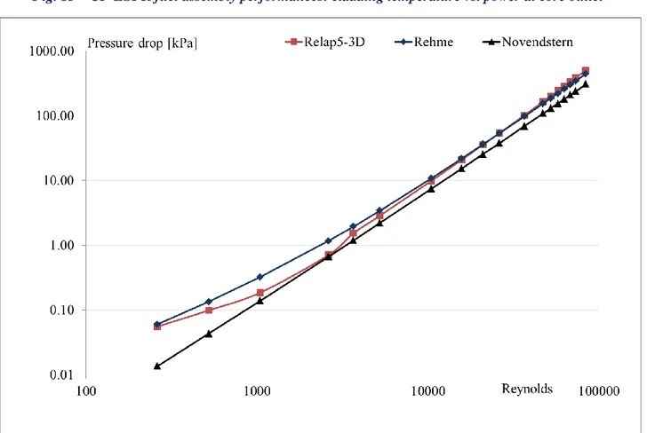
geometrical verification, i.e. comparisons between geometry of design and nodalization features, the evaluation of the pressure drop in the wire wrapped fuel assembly as function of Re, see Fig. 14, the verification of the heat transfer performance of the FA at different power levels (uniform linear
power is imposed), Fig. 12 and Fig. 13,
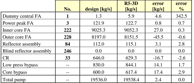
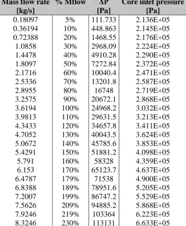
pressure drop along the loop in isothermal conditions (or steady state conditions), mass flow distributions in primary system, see Tab. 5,
ACS
Core FA, bypass, strongback
Hot region lower part
Hot region upper part
Cold region IHX PS Vessel cooling system Diagrid PMP
performances of the heat exchange in the IHX at different operating modes, pumps performances verification.
The verification of steady state results at nominal conditions will be performed when the model will be updated with the neutronic data. Then, it will be applied to the investigation of TH core safety parameters with different fuel prototypes and the simulation of postulated accidents :
No. design [kg/s] R5-3D [kg/s] error [kg/s] error % Dummy central FA 1 1.3 5.9 4.6 342.5 Power peak FA 3 121.9 122.7 0.8 0.7 Inner core FA 222 9025.3 9052.3 27.0 0.3 Outer core FA 228 8197.0 8151.5 -45.5 -0.6 Reflector assembly 84 112.0 115.1 3.1 2.8
Blind reflector assembly 246 0.0 0.0 0.0 0.0
CR 33 646.0 629.3 -16.7 -2.6
Low press bypass -- 830.0 844.1 14.1 1.7
Core bypass -- 600.0 617.4 17.4 2.9
Total pump -- 19536.0 19538.4 2.4 0.0
Tab. 5 – CP-ESFR nodalization. Mass flow distribution in primary system: design data vs. code results
Fig. 13 – CP-ESFR fuel assembly performances: cladding temperature vs. power at core outlet
Fig. 14 – CP-ESFR fuel assembly performances: friction losses in wire wrapped fuel assembly vs. experimental based empirical correlations.
1.4 Conclusive remarks and follow up
A RELAP5-3D© nodalization of pool type sodium cooled fast reactor, CP-ESR, has been developed and set up. The hydraulic performances of the nodalizations in terms of flow and pressure distributions are satisfactory. The implementation of the pump model and of the homologous curves for the head and torque for single phase operation is carried out.
Tests on the modeling of the FA performances have been completed. Friction pressure losses in the wire wrapped fuel assembly zone have been compared with correlations available in literature. The heat exchange performances have been tested with constant linear power in the active zone and setting Todreas Carelli correlation.
The nodalization will be completed implementing the neutronic data and the power distribution calculated in the framework of the LP2 A3 task of the AdP2012. Then, it will be applied to investigate specific accident scenarios for providing input data to 1) a full core thermal-hydraulic model of CP-SFR and 2) to a fuel pin performances code.
1.5 References
[1] Fiorini, G.L., 2009. The Collaborative Project on European Sodium Fast Reactor (CP ESFR), FISA 2009, 22-24 June, Prague, Czech Republic
[2] G.L. Fiorini, A. Vasile, D. Blanchet et al, “ESFR „Working Horses‟ Core Concept Definition”, CEA Cadarache, 2009
[3] B. Vezzoni, A. Rineiski, F. Gabrielli, W. Maschek, M. Marchetti, Optimized ESFR core with Minor ctinides, KIT, Karlsruhe, January 2012
[4] J. Krepel (PSI), K. Mikityuk (PSI), O. Huml (PSI),H. Tsige-Tamirat (JRC.IE), L. Ammirabile (JRC.IE),D. Blanchet (CEA), F. Polidoro (RSE), “Working horses” ESFR core concepts: neutronic and thermal-hydraulic characteristics, PSI Villigen, November 2010
[5] R. Sunderland, V. Sheth, L Buiron, P. Tetart, S. Massara, H. Tsige-Tamirat, A. Rineiski, B.Vezzoni, F. Gabrielli, M. Marchetti, D. Zhang, M. Flad, W. Maschek, J. Krepel, K. Sun, K. Mikityuk, R. Ochoa, N. García‐ Herranz, D. Cuervo, C. Ahnert, ESFR Cores with Optimised Characteristics – Final Report, AMEC , November 2012
[6] GENOT Jean-Sebastien, ESFR Working Horse Pool Concept Description, AREVA, July 2009 [7] CP-ESFR-OC-Vademecum.xls
[8] Rineiski, B. Vezzoni, F.Gabrielli, W. Maschek, M. Marchetti, A. Omenetto, X.-N. Chen, D. Zhang, H. Tsige-Tamirat, K.Sun, J. Krepel, K. Mikityuk, D. Rochman, A.J. Koning, D.F. DaCruz, F. Polidoro, Synthesis of options to optimize feedback coefficients, Final Report, KIT, Karlsruhe, February 2012 [9] The RELAP5-3D©Code Development Team, RELAP5-3D© Code Manual Volume IV: Models and
2 D
EVELOPMENT AND SET UP OFEBR-II
NODALIZATION BYRELAP5-3D©
V4.0.3
CODE2.1 Framework
The activity discussed in the present section is connected with the international CRP “Benchmark Analyses of an EBR-II Shutdown Heat Removal Test” promoted by IAEA [3].
The CRP addresses Shutdown Heat Removal Tests (SHRT) performed at the Experimental fast Breeder Reactor EBR-II within the framework of the US Integral Fast Reactor development and demonstration programme. The CRP is aimed at improving the participants' simulation capabilities in the various fields of research and design of sodium cooled fast reactors through data and codes validation and qualification. The scope of the CRP is twofold: firstly, validation of the state-of-art liquid metal cooled fast reactor codes and data used in neutronics, thermal hydraulics and safety analyses, and, secondly, training of the next generation of fast reactor analysts through international benchmark exercises.
The report presents the TH nodalization developed and set up by REALP5-3D© code. 2.1.1 EBR-II plant overview
The EBR-II plant is located in Idaho and was designed and operated by Argonne National Laboratory for the US Department of Energy. Operation began in 1964 and continued until 1994. EBR-II was rated for a thermal power of 62.5 MWt with an electric output of approximately 20MWe.
EBR-II is a sodium-cooled reactor with three loops, characterized by the following mass flow rates: Primary sodium: 485 kg/s
Intermediate sodium: 315 kg/s Secondary steam: 32 kg/s
All primary system components were submerged in the primary tank, which contained approximately 340 m3 of liquid sodium at 371°C. An argon cover gas was maintained over the surface of the sodium in the primary vessel to minimize the opportunity for air to contact the sodium.[2] Fig. 15 shows the primary tank and the other components The primary cooling system consisted of two mechanical centrifugal pumps operated in parallel and pumping a total of 485 kg/s of sodium.[2] The two pumps drew sodium from this pool and provided sodium to the two inlet plena for the core. Subassemblies in the inner core and the extended core regions received sodium from the high-pressure inlet plenum, accounting for approximately 85% of the total primary flow. The blanket and the reflector subassemblies in the outer blanket region received sodium from the low-pressure inlet plenum.
Hot sodium exited the subassemblies into a common upper plenum where it mixed before passing through the outlet pipe into the intermediate heat exchanger (IHX). The pipe feeding sodium to the IHX is referred to as “Z-pipe”. Sodium then exited the IHX back into the primary sodium tank before entering the primary sodium pumps again.
Sodium in the intermediate loop traveled from the IHX to the steam generator where its heat was transferred to the balance-of plant (BOP). The colder sodium intermediate loop then traveled through a similar length of piping back to the IHX. The steam generator consisted of two parallel superheaters and seven parallel evaporators. Fig. 16 shows a simple schematic of the primary, intermediate and steam systems. Note that th power, flow and temperature conditions described earlier are for typical EBR-II operation..
The reactor-vessel grid-plenum assembly accommodated 637 hexagonal subassemblies. The subassemblies were segregated into three regions: core, inner blanket (IB) and outer blanket (OB). The central core comprised 61 subassemblies in the first five rows. The inner blanket region was composed of Rows 6 and 7.
Originally these rows were loaded with blanket subassemblies. But for SHRT-17, no blanket subassemblies were loaded in this region. Instead, Row 6 contained the driver-fuel and irradiation subassemblies of the expanded core and Row 7 contained reflector and subassemblies. The outer blanket region comprised the 510 subassemblies in Rows 8-16, which were either blanket or reflector subassemblies.
EBR-II was heavily instrumented to measure mass flow rates, temperatures and pressures throughout the system.
The EBR-II reactor core vessel grid-plenum assembly accommodated 637 hexagonal subassemblies, which were installed in one of three regions: central core, inner blanket (IB) or outer blanket (OB). Fig. 18 illustrates the subassemblies arrangement of the reactor and the subassembly identification convention. Each subassembly position was identified by a unique combination of three parameters: row, sector and position within the sector. Subassembly row identification begins at Row 1 for the subassembly in the core-center and moves outward to Row 16. Row 1 had one subassembly, Row 2 had six subassemblies. From Row 2 outward to Row 14, each row had 6 more subassemblies than the last. Rows 15 and 16 were not complete rows and had 66 and 24 subassemblies, respectively.
Each row was broken up into six sectors A through F. As each row approximated a hexagon, each side of the row was assigned to one of the six sectors. The final parameter needed to identify a subassembly location is the position within the sector. The line of subassemblies dividing sectors A and F were defined as the subassemblies in position 1 of their respective rows within the sector A. The line of subassemblies that divide sector a and B are therefore defined as the subassemblies in position 1 of their respective rows within sector B. This patterns continues for the remaining four sides of the core layout. As an example, the subassembly XX09 is positioned in subassembly location 5D3, where 5 is the row, D is the sector and 3 is the position within the sector.
The central core comprised the 61 subassemblies in the first 5 rows. Two of these positions contained safety-rod subassemblies and eight positions contained control-safety-rod subassemblies. These subassemblies are identified by the letter S and C, respectively, in Fig. 17. Two positions in Row 5 contained the in-core instrument subassemblies (INSAT) XX09 and XX10, and one position in Row 5 contained the in-core instrument test facility (INCOT) XY16. The remaining central core subassemblies were either driver-fuel or experimental-irradiation subassemblies of varying types. For SHRT-17 test only the MARK-II A I type driver subassembly was used.
In Fig. 17, driver subassemblies are denoted by the letter D, instead the letter P indicates a partial driver, which are driver subassemblies where approximately half of the fuel elements are replaced by steel elements. HFD in Fig. 17 refers to a high-flow driver, all of which were located in Row 6. A high flow driver subassembly was the basic driver subassembly with extra inlet flow holed drilled into the subassembly inlet nozzle region to allow higher subassembly coolant flow.
The expanded core region was composed of Rows 6 and 7. This region is also named inner blanket region because originally housed blanket subassemblies. But for SHRT-17 test no blanket subassemblies were loaded in this region. Instead Row 6 contained the driver-fuel and irradiation subassemblies and Row 7 contained reflector subassemblies. The outer blanket region comprised the 545 subassemblies in Rows 8-16, which were either blanket or reflector subassemblies. In Fig. 17 reflector subassemblies are identified with the letter R.
In Fig. 17. those subassemblies whose label begins with letter K were steel subassemblies; The remaining subassemblies are all experimental or driver-irradiation type subassemblies. Fig. 18 illustrates the rest of the core.
The outer configuration of all subassemblies was very similar. The upper adapter was formed to fit the top of the hexagonal outer tube of the central region and the top part of the upper adapter was slotted to adjust the orientation of the subassembly within the reactor grid. The lower surface of the mushroom-shape head on the upper adapter provided a solid surface for grasping during fuel handling with gripper devices.
The center region of each subassembly was surrounded by a hex tube, which created an independent flow channel for each subassembly. Each face of the hexagonal tube contained a spacer button, formed by dimpling the tube wall outward. The buttons served to prevent the subassemblies from touching if bowing were to occur.
The lower adapter positioned the subassembly within the reactor grid and determined the amount of coolant flow through the subassembly. Subassemblies that were to be positioned in Rows 1 through 5 had core-type lower adapters. The core-type adapter was a stainless steel, machined cylindrical nozzle. The upper portion had a rounded shoulder, which sat in the hole of the upper grid plate in the core region. The core region lower adapters had four sets of coolant flow holes. Depending on the row in which the subassembly was position, a different number of flow holes were covered by the various step sizes of the lower grid plate. The expanded core-type lower adapter was used for driver fuel in Row 6 and irradiation subassemblies located in Rows 6 or 7 of the reactor. The inner blanket lower adapter with two sets of flow holes was used for the subassemblies, other than driver fuel type, located in Rows 6 or 7. The outer blanket lower adapter was used for subassemblies in Rows 8-16. These adapters fit into stainless steel tubes that interconnected the upper and lower grid of the reactor grid assembly to provide a flow path from the low-pressure plenum. Yet another type of lower adapter was used for the control rod and safety rod subassemblies.
The inner configuration of the center section of subassembly varied depending upon the specific subassembly type. For each subassembly type that include fuel elements Tab. 6 presents the nominal design parameters of the fuel element by type and gives design data for the wire-wrapped cladded fuel elements. Tab. 7 presents the nominal design parameters for the subassembly hexagonal duct wall.
Fig. 19 shows an isometric view of the inner configuration of a MARK-II AI subassembly. The center section of the MARK-II AI subassembly consisted of an upper shield, a core bundle of fuel elements and a lower shield. The MARK-II AI and MARK-II A fuel elements were part of the central core driver and expanded core driver subassembly designs. The MARK-II S element was used in the high worth control rod design.
Each fuel element clad tube contained a single metal fuel slug. U-5Fs is the fissium alloy uniquely developed and fabricated for the Argonne EBR-II reactor. The fuel element were sodium bonded. Above the sodium bond level was a fission gas plenum that was initially filled with an inert gas until fission gas was produced. The inert gas used was Helium with Xenon tracer isotope added for tagging a leaking fuel element.
The EBR-II coolant systems model for the SHRT-17 test includes the major components in the primary sodium circuit and the intermediate side of the intermediate heat exchanger. Beginning at the outlet of the reactor core, the primary sodium circuit includes the upper plenum, reactor outlet piping, auxiliary EM sodium pumps, reactor inlet piping and high- and low-pressure inlet plena. The inlet ad outlet of the intermediate side of the heat exchanger are boundary conditions for the model.
Fig. 20 illustrates the major components in the EBR-II primary sodium circuit. Sodium discharged from the two pumps into the reactor outlet piping, which is known as the „Z-Pipe‟. The shape of the pipe accommodates thermal expansion. The top of the Z-Pipe contained the auxiliary EM pump, with rated to provide up the 0.5% of the nominal pump head.
Sodium exited the Z-Pipe and entered the shell side of the intermediate heat exchanger. Cold sodium was the discharged into the primary sodium tank. The two primary sodium pumps took suction from the primary sodium tank and provided sodium to the reactor inlet piping. Fig. 20 [2] shows the two primary sodium pumps and their inlet piping. Both sets of inlet piping provided sodium to the high-pressure and low-pressure inlet plena. The high pressure inlet plenum provided sodium to the subassemblies in the first 7 rows; while the low-pressure inlet plenum provided sodium to Rows 8-16.
The primary tank is the outer boundary of the primary sodium circuit and is modeled as a vertically oriented cylinder. It encompasses all of the major primary sodium components. The reactor vessel, intermediate
exchanger and two primary sodium pumps are modeled as vertically oriented cylinders. Sodium piping is modeled as a series of straight pipes connected by pipe bends that, unless otherwise stated, have a bend radius equal to the pipe radius. The reactor vessel, IHX, pumps and sodium piping are assumed to be the only components that displaced sodium in the primary tank. The main characteristics of the all components are given in the following sections.
The cylindrical primary sodium tank, illustrated in Fig. 21 contains two vessel walls with the space between the inner and outer vessel walls filled with argon gas. Outside of the inner vessel wall is the argon layer; outside of the argon gas layer is the outer vessel wall. Both vessel walls are composed of Type 304 stainless steel
The total volume of sodium in the primary system is approximately 340.69 m3 at an average nominal temperatures of 644.26 K. This volumes of sodium includes all sodium in the major components, piping, reactor subassemblies and primary tank sodium is occupied by argon gas. The core support structure below the reactor vessel is assumed to displace a negligible amount of the sodium.
The EBR-II reactor vessel and its internal components are illustrated in Fig. 22. Sodium discharged from the primary sodium pumps entered the low-pressure inlet plenum from the two inlet pipes or the high-pressure inlet plenum. Sodium from these two inlet plena was provided to the reactor subassemblies and then discharged into the common upper, or outer plenum. Sodium exited the upper plenum through the Z-Pipe. The neutron shielding surrounded the reactor, upper plenum and lower plena with sections removed from the inlet and outlet piping. Other than the grid plates that separated the lower plena, there was no significant shielding below the reactor. Above the upper plenum sat the reactors cover, through which control rod drive shafts and instrumentation leads entered the reactor vessel.
Fig. 23 below illustrates the EBR-II high- and low-pressure inlet plena.
The lower plenum received coolant from the two low-pressure inlet pipes. Sodium passed through a vertically oriented baffle plate with 50 baffle flow holes, then passes through a horizontally oriented baffle plate with 592 baffle holes and into the low-pressure inlet plenum Sodium enters one of the 510 outer blanket stainless steel tubes that feed the outer blanket region subassemblies (Rows 8-16), which are identified in Fig. 23. All structure in the inlet plena is composed of Type 304 stainless steel.
The upper inlet plenum received sodium from the two high-pressure inlet pipes. Sodium then passed through a vertical baffle plate, around the stainless steel tubes connecting the low-pressure plenum with the core, and into the high-pressure inlet plenum. In the high-pressure inlet plenum, sodium was distributed to the subassemblies in Rows 1-7.
The central core region of the high-pressure inlet plenum contains a series of seven concentric hexagonal steps. Each step has an aperture for each subassembly in the row in which the bottom of each subassembly is inserted. As the lower adapter of each subassembly in Rows 1-7 has a series of sodium inlet flow holes, these steps have varying heights to block off certain holes depending on the desired amount of sodium flow through the subassembly.
The actual EBR-II upper plenum contained a baffle plate to mix the outlet sodium flow. Not enough detail is available, it assumed that the sodium leaving the upper plenum is fully mixed when it enters the reactor outlet pipe.
The upper plenum consists of two regions: a cylindrical region directly above the reactor subassemblies and an annular region surrounding the cylindrical region. Sodium leaves the upper plenum through the reactor outlet pipe and into the Z-Pipe.
The primary sodium circuit has three pumps: two main and one electromagnetic pump. The two main primary pumps lay opposite each other at a radius of 3.251 meters from the center of the core. Primary sodium pump #1 was located 120° counter-clockwise from the IHX, while the primary sodium pump #2 was located 60° clockwise from the IHX. The electromagnetic pump was located around part of the Z-Pipe. Both types of pumps are assumed to constructed of Type 304 stainless steel.
Two sets of sodium piping were installed in the primary sodium circuit: the reactor outlet and the reactor inlet piping. The reactor outlet pipe, or Z-Pipe, began at the reactor outlet plenum and ended at the intermediate exchanger. It was constructed in a Z-shape to account for thermal expansion during periods of elevated outlet and cold pool sodium temperatures. The reactor inlet piping was two identical sets of piping from both the primary sodium pumps to the inlet plena. Both sets of piping were constructed of Type 304 stainless steel. In the following piping descriptions, the x-axis is assumed to be on the line between the axial centerlines of the reactor core and IHX.
Because the sodium in the reactor outlet pipe is at higher temperature than the bulk sodium surrounding it, the Z-Pipe is a double-walled structure. The annular region between the two pipe walls is filled with static sodium. In the upper section of the Z-Pipe resides the auxiliary EM pump.
The intermediate heat exchanger transfers heat from the radioactive primary system to the intermediate system and isolates the primary system from the water inventory in the steam plant. The heat exchanger is a tube-and shell design with single-wall straight tubes and is operated in the counter flow mode.
The heat exchanger consists of three modules or components, all composed of Type 304 stainless steel. The well casing is a cylindrical annulus with its major axis oriented vertically and it hangs from the primary tank cover from a lip at the upper end of the well casing and continues downward to an elevation of 1.559 meters above the bottom of the active core. It consists of four concentric steel cylinders with stagnant sodium between each layer. The lower end of the casing is terminated by a hemispherical head. Welded to the top of the tube bundle is the shield plug. Once the tube bundle and shield plug are lowered as a unit into the well casing, a cover is placed over the open end of the well casing and welded shut.
Heat transfer from primary to intermediate sodium takes place in the lower half of the intermediate exchanger where the tube bundle is located. The primary coolant is admitted on the shell side through a horizontal inlet pipe (i.e. the outlet of the Z-Pipe) that penetrates the well casing wall 4.939 meters above the bottom of the active core. The fluid exits the inlet pipe and enters the upper region of the tube bundle, where it is distributed horizontally by baffles. The upper end of the tube bundle (above the inlet pipe) is terminated by the upper tube sheet, resulting in the primary sodium being directed downward parallel to the tubes. The primary sodium travels down the length of the tubes and exits the well casing horizontally just above the lower tube sheet through an annular opening in the well casing.
The intermediate sodium enters the intermediate heat exchanger through a vertical pipe that penetrates the well casing cover. This pipe extends down the length of the well casing to the hemispherical region defined by the lower tube sheet and the well casing lower hand. A set of hemispherical baffles redirect the fluid 180° so that it flows upward. The fluid then enters the bottom of the tubes at the lower tube sheet. The fluid flows up the length of the tubes and then exits the tubes into another hemispherical-shaped region defined on its bottom by the upper tube sheet and on its upper side by a hemispherical-shaped spun from metal. An exit pipe is welded to the hemispherical cap. The exit pipe travels the length of the upper-half of the well casing up to the well casing cover, where it exits the intermediate heat exchanger through a penetration the well casing cover.
The collection of internals in the upper half of the well casing is known as the shield plug. The shield plug contains the inlet and the outlet intermediate side pipes, while the remaining space is occupied by various thermal and radiation shields. The shield plug represents a large thermal connections to both the primary and intermediate flow paths are rather weak, with time scales on the order of seconds or minutes. The areas available for heat transfer and the radius of the shield plug are such that the heat transfer rates are small compared to the energy storage capability of the shield material.
PIN GEOMETRY MARK-II AI MARK-II A MARK-IIS XX09 XX10 Outer Blanket
Number of pins 91 91 61 59 18 19
Number of elements 61
Fuel alloy U-5Fs U-5Fs U-5Fs U-5Fs
Stainless
Steel Depleted U Fuel -slug lenght [m] 0.3429 0.34290 0.3429 0.3429 N/A 1.397 Fuel-slug diameter [m] 0.0336 0.0336 0.0336 0.0336 N/A 0.01109 Cladding-wall thickness
[m] 0.00032 0.00032 0.00032 0.00032 Solid rod 0.000457 Cladding-wall OD [m] 0.00441 0.00441 0.00441 0.00441 0.00881 0.01252 Element lenght [m] 0.6108 0.6362 0.5334 0.6108 0.6108 1.575 Restrainer height above
fuel [m] 0.0127 0.0127 0.0127 None N/A
Sodium level above fuel
[m] 0.03175 0.00635 0.00635 0.03175 N/A 0.03048
Plenum gas Inert gas Inert gas Inert gas Inert gas N/A Inert gas
Cladding Material 316 316 316 316 316 304
Spacer-wire diameter [m] 0.00124 0.00124 0.00124 0.00124 0.00124 None
Spacer-wire material 316 316 316 316 316 N/A
Spacer-wire pitch [m] 0.15240 0.15240 0.15240 0.15240 0.15240 None
Tab. 6 - EBR-II design parameters (nominal) of subassembly fuel elements.
MARK-II AI MARK-II A XX09 XX10 Safety HWCR Reflector Uranium Blanket
Pitch center to center [m] 0.05893 0.05893 0.05893 0.05893
OUTER HEX TUBE
Flat to flat outside [m] 0.05817 0.05817 0.05817 0.05817 Flat to flat inside[m] 0.0561 0.0561 0.0561 0.0561
Material 316SS 304SS 304SS 304SS
INNER HEX TUBE
Flat to flat outside [m] 0.0484 0.0484 Flta to flat inside [m] 0.0464 0.0464
Material 304SS 304SS
Upper Adapter/Fixture 304SS 304SS 304SS Upper Axial Shield 304SS 304SS
Lower Axial Shield 304SS 304SS
Lower Adapter 304SS 304SS 304SS