University of Pisa and Scuola Superiore
Sant’Anna
Master Degree in Computer Science and Networking
Corso di Laurea Magistrale in Informatica e Networking
Master Thesis
Multithreaded support to
interprocess communication in
parallel architectures
Candidate
Supervisor
Tiziano De Matteis
Prof. Marco Vanneschi
There is nothing so stable as change
Ringraziamenti
La Laurea `e senz’altro uno dei momenti pi`u importanti nella vita di una per-sona; mi sembra quindi doveroso e giusto condiverla con chi, in tutti questi anni, mi `e stato vicino.
Il primo, enorme, grazie, va senz’altro alla mia famiglia: pap`a, mamma e sorellina. Molte delle difficolt`a affrontate in questi anni sarebbero state in-sormontabili se non avessi avuto voi alle mie spalle, pronti a sorreggermi nel momento del bisogno. Insieme a loro, un pensiero va anche a tutti gli altri parenti: zii, nonne, cugini e cugine.
Un sentito ringraziamento va al prof. Marco Vanneschi, per avermi fatto ap-prezzare una branca dell’informatica per me nuova e, in generale, a quei pro-fessori che in questi anni hanno contribuito al mio amore per questa disciplina scientifica.
Passando al lato amici, qui la lista `e lunga, ma permettetemi di iniziare con due ringraziamenti particolari. Il primo va ad Andrea e Bianca, con cui ho condi-viso sei anni di vita universitaria e, spero, di condividere tante altre avventure. Incontrare persone di una simile bont`a `e abbastanza raro e io, in questo, mi ritengo molto fortunato: grazie. Il secondo va ad Andrea e Luigi, compagni fedeli di universit`a. In questi anni, fra le trollate di Andrea e i piani industriali che ho condiviso con Luigi, siete sempre stati pronti ad offrirmi un buon con-siglio e un appoggio, per me fondamentale.
Come non ringraziare poi i miei coinquilini del Rosellini, vecchi e nuovi: Momo, Nicola, Luca, Dima, Ivan, Peppe, Diana, Manu, Nicol`o, Salvatore, Guido e tutti gli altri che ora mi stanno sfuggendo. Condividere con voi lo stesso tetto, `e
come far parte di una grande famiglia allargata e, proprio per questo, l’aver vissuto in una casa dello studente sar`a un’Esperienza che mi porter`o dentro per sempre, insieme alle vostre amicizie. Al loro fianco, un grazie va anche a Livia e Chiaretta (durigh`en!), protagoniste di tante belle serate passate assieme in quel di Pisa.
Lato universit`a, un grazie va senz’altro ai colleghi del Lab (booon per voi): Fabio e Albe, con cui ho condiviso l’avventura ”tesistica”, il Good, fonte di tanti consigli, quel numerico americano del Gufetto, Dani, Alessio e il Farru. Vanno ringraziati anche tutti gli altri compagni di studio: Ema, Alessio, Cic-cio, St`e, Gab, il Boggia, Monica, Mary, il Pucc, Anna, il Fulge, Victor, Elian, Alice, tutti gli MCSN guys (un giorno troverete quella spia, ve lo auguro) e quel mio tempio personale che `e la biblioteca di scienze!
Un pensiero sentito, lo dedico anche ai miei amici di gi`u: Serse, Pino, Tuta grande e Tuta piccolo, Junior, Teddy, i Cab`u e Francesco ... nonostante passi con voi poche settimane all’anno, `e come se non me ne fossi mai andato da Taviano. Vi porto nel cuore.
Sorrido di gioia nel vedere questa lunga lista e mi scuso con chi, per mia dis-attenzione, non `e stato citato. Tante cose sono successe in questi anni, ma non posso che soffermarmi sul fatto che ognuno di voi mi ha lasciato dentro qualcosa.
Grazie.
Contents
1 Introduction 1
2 Multithreaded Architectures 7
2.1 Taxonomy of multithreaded architectures . . . 9
2.1.1 Interleaved Multithreading . . . 9
2.1.2 Blocking Multithreading . . . 10
2.1.3 Simultaneous Multithreading . . . 11
2.2 Intel’s Hyper-Threading Technology . . . 12
2.3 Multithreading in Parallel Computing . . . 13
2.3.1 Speculative Precomputation . . . 15
3 Communication in parallel applications 17 3.1 Overlapping communication and computation . . . 19
3.2 Communication processor . . . 21
3.2.1 Commercial implementation of communication processors 24 4 Multithreaded support for interprocess communication 27 4.1 Programming in multithreaded architectures . . . 29
4.2 Inter-thread synchronization mechanisms . . . 30
4.2.1 POSIX . . . 31
4.2.2 Spin lock . . . 32
4.2.3 MONITOR/MWAIT instructions . . . 34
4.3 Runtime support of LC . . . 39
4.3.1 Zero copy optimization and shared memory segment . . . 39
4.3.2 Channel descriptor . . . 40
4.3.3 Send and receive primitives . . . 44
4.4 Communicator implementation . . . 46
4.4.1 Communicator initialization . . . 47
4.4.2 Delegation queue . . . 47
4.4.3 Check buffer full . . . 48
4.4.4 Send completion notification . . . 49
4.4.5 Communicator finalization . . . 49
4.4.6 Evolution of communication primitives . . . 50
5 Tests and results 53 5.1 Stream computation . . . 54
5.2 Data parallel computation . . . 60
6 Conclusions and future works 67
CHAPTER
1
Introduction
Hardware multithreading is becoming a generally applied and commercially diffused technique in modern processors. Provided that proper architectural supports to program concurrency are available, during the same time slot, or a limited number of time slots, the units of a multithreaded (MT) processor are simultaneously active in processing instructions belonging to distinct programs. Underutilization of a superscalar processor, due to missing instruction level pa-rallelism, can be overcome by this technology: the latency of any long-latency event (such as cache misses or long instruction executions) can be hidden by allowing multiple programs to share functional units of a single processor in an overlapping fashion.
The parallel activities executed by a multithreaded CPU are referred to using the term hardware thread : this is a concurrent computational activity sup-ported directly at the firmware level. A specific runtime support of threads is implemented directly at the firmware level in order to be able to execute different threads simultaneously.
Theoretical and experimental results show that multithreading is well suited in a multiprogram environment, achieving a scalability that ranges in the interval 1.4-2.4 for a number of threads in the interval 2-8. Nonetheless, how to
ex-ploit this technology in High Performance Computing (HPC), in a systematic manner, is still unknown. Since parallel applications usually exhibit an high exploitable degree of parallelism, an obvious solution seems to be to increase the parallelism degree in order to exploit all the thread contexts offered by a multithreaded machine. Unfortunately this simple solution does not give the expected results: indeed, contention for shared resources limits the perfor-mance advantages of multithreading on current processors, leading to marginal utilization of multiple hardware threads and even to a slowdown.
In the literature many researches suggest the use of cooperating threads to increase the performance of a computation. Speculative precomputation (SPR, [4]) is an example of such techniques: it utilizes idle hardware thread contexts to execute helper threads on behalf of the main one. These threads, speculati-vely prefetch data that are going to be used by the main computation thread in the near future, thus hiding memory latencies and reducing cache misses. Ex-perimental tests conducted on commercial multithreaded platforms show that, on a pool of benchmarks, SPR could give some benefits in some cases, while performs comparably to the classical program version in the rest.
The work of this thesis aims at investigating an alternative use of multithread-ing, by utilizing this technology as a support for efficient interprocess commu-nications in parallel applications.
The working context: communications in parallel applications
The field of HPC is living a new impetus in recent years, thanks to the fact that multi-many core components, or on chip multiprocessors, are replacing uniprocessor based CPU, also at a commercial level. This fact has enormous implications on technologies and applications: in some measure, all hardware-software products of the next years will be based on parallel processing. In a structured view to parallel programming, a parallel application can be seen as a set of cooperating modules that operate together to achieve a common goal; assuming a local environment (or message passing) model, this cooperation is
3 achieved by an exchange of informations between modules through communi-cation channels.
Parallel programs are expressed as structured computation graphs, via high-level parallel programming tools, and are usually compiled into a set of cesses in which the mentioned cooperation is expressed using concurrent gramming languages. The basic interprocess communication primitives pro-vided by such languages are send and receive commands; they are used for transferring a message from a sender to a receiver through a communication channel.
Since these processes alternate calculus and communication phases in a se-quential fashion, it is evident that considerable advantages can be obtained by allowing the overlap between them. Supposing that proper architectural sup-ports exist, a module can delegate the execution of a communication primitive to a secondary entity, going ahead with the calculus without waiting for its com-pletion; in the meanwhile and in parallel the communication is performed by such secondary entity. In general, hiding the communication latency (at least in part) is allowed, resulting in a performance benefit that depends by various factors such as the structure of the application, the particular architecture, the amount of communications performed with respect to the computation. An example of such supports is the communication processor, that could be reali-zed as a central, or as an input-output, coprocessor specialireali-zed at the firmware level. In particular, the input/output coprocessor solution is adopted when the communication processor is provided inside the interconnection network box.
The goal of this thesis is to realize a proper runtime support, for shared memory systems, of a basic concurrent language (LC, introduced in the HPC courses of the Master Program [19]), including the emulation of the communication processor facility through multithreading. The idea is to associate to each computational module (mapped as a process or a thread) one (or potentially more) thread that is in charge of executing the communication primitives, fol-lowing a philosophy similar to the communication processor case. Performing basically a burst of load or store for transferring a message, hopefully the new
thread will not interfere with the computational one. Research issues
Keeping in mind that the main objective is to implement a proper runtime support for LC, as library, on a MT architecture, through this thesis various problems will be addressed:
• understand how a multithreaded CPU actually works, what could be its limits (with a reference to a real architecture that will be used for the development) and what precautions take in programming in order to use it properly;
• how to efficiently implement the runtime support for the concurrent lan-guage, taking into account some optimizations that will be introduced (in particular the zero copy technique). It must be designed in a proper way to be executed in user space, saving additional overheads otherwise unavoidable;
• as explained, to each process/thread of the parallel application is associ-ated at least one thread that is in charge of executing the delegassoci-ated com-munication primitives. Considering the context of a MT machine, where the threads share the functional units of a processor, there is the need of understanding how properly manage the interactions between them, looking for mechanisms that have properties of high responsiveness and lightweightness.
Even if they will treated with reference to a particular system, these problems and their proposed solutions could be considered quite commons in exploiting these kind of architectures.
This work will allow us to determine whether the proposed use of multithread-ing is actually a viable alternative to other proposals and what benefits can results in parallel applications.
5
Structure of the thesis
This documents deal with the mentioned topics and it is structured in the following way:
1. in Chapter 2 the multithreading technique will be introduced in details. A brief taxonomy of multithreaded architectures and a commercial im-plementation (the Intel’s Hyperthreading Technology) will be presented. Finally a brief discussion on the current use of multithreading in HPC is approached;
2. in Chapter 3 the impact of communications in parallel applications and the benefit of overlapping them with computation will be discussed. The communication processor is described, presenting some concrete imple-mentations;
3. Chapter 4 deals with all the implementation details of this work. Mea-sures to be adopted in programming, for efficiently exploit multithreaded system, are presented, with a particular attention on possible mecha-nisms for efficiently synchronizing two threads. Then the runtime sup-port for a minimal core of LC in shared memory system is introduced and, subsequently, it is described how extend it in order to emulate the communication processor facility through multithreading;
4. in Chapter 5 results obtained from the comparison of the two different versions of the runtime support for LC, with or without the emulation of communication processor facility, are discussed;
5. finally, in Chapter 6 conclusions on the work done are reached and pos-sible ideas for future works are briefly pointed out.
CHAPTER
2
Multithreaded Architectures
In the last few decades there has been an increasing complexity in proces-sors design in order to achieve an ever increasing performance improvement. The earlier scalar pipelined CPUs evolved introducing new techniques such as branch-prediction, out of order and superscalar execution. Nonetheless, the major complexity design, transistor counts and power consumption that this solutions imply, do not correspond to a proportional increasing in processors performance.
Consider, as an example, a superscalar architecture. Superscalar microproces-sors are able to issue multiple instructions (two to eight) each time slot (1-2 clock cycles) from a conventional linear instruction stream. To accomplish this goal, proper version of the functional units of a scalar pipelined CPU must be realized, in order to be able to offer a given average bandwidth. As the issue rate of microprocessors increases, the compiler or the firmware architec-ture will have to extract more instruction level parallelism (ILP) from a single sequential program to fully exploit these additional resources. However, ILP found in a conventional instruction stream is limited and this results in per-formance degradations caused by frequent data dependencies. Optimizations aim to mask latencies caused by such dependencies.
among instructions of distinct sequential programs running on the same ILP CPU, by means of multithreaded architectures (MT architectures). Provided that proper architectural supports to program concurrency are available, this idea implies that during the same time slot, or a limited number of time slots, the CPU units are simultaneously active in processing instructions belonging to distinct programs. Allowing multiple programs to share functional units of a single processor in an overlapping fashion, multithreading can potentially hide the latency of any long-latency event (such as cache misses or long instruction executions).
The parallel activities executed by a MT CPU, on a time slot basis, are referred to using the term thread (or hardware thread in the literature), with a more specific meaning with respect to its traditional notation. Here a thread is still a concurrent computational activity but is supported directly at the firmware level. For this purpose, the firmware architecture of a MT CPU, able to execute at most m threads simultaneously, has to provide:
• m independent contexts, where, as usually, a context is represented by the program counter and the registers visible at the assembler level; • a tagging mechanism to distinguish instructions of different threads within
the pipeline;
• a thread switching mechanism to activate context switching at the thread level.
This means that there is a specific runtime support of threads implemented directly at the firmware level. From the programmer viewpoint, this may be not visible: a thread can be declared in the usual way, for example as a user or system thread, by means of Posix threads. However the compiler of a MT machine is different from a traditional one: it produces proper code to link the firmware level runtime support for threads.
In the following sections a brief taxonomy of multithreaded architectures will be given. Then a commercial implementation of a multithreading technique,
2.1. Taxonomy of multithreaded architectures 9 the Intel Hyperthreading Technology (that will be used also for development and testing), will be described and, finally, common use of multithreading in parallel computing will be discussed.
2.1 Taxonomy of multithreaded architectures
Multithreaded architectures fall into two main categories, according on how instruction emission is performed:
• single-issue architectures: during a time slot only instructions belonging to a single thread are issued; instructions belonging to distinct threads are issued in distinct time slots. This class can be implemented either on a scalar or on a superscalar architecture. In this category, a further distinction exists between Interleaved Multithreading and Blocking Mul-tithreading;
• multiple-issue architectures: during a time slot instructions belonging to more than one thread can be issued. This class, which can be im-plemented only on superscalar architectures, is also called Simultaneous Multithreading.
2.1.1 Interleaved Multithreading
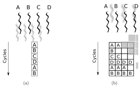
In the Interleaved Multithreading (IMT) approach, in every processor time slot a new instruction is chosen from a different thread that is ready and active, so that threads are switched every slot (Figure 2.1). If one of them incurs in a long latency event, it is simply not scheduled until that event completes. The key advantage of the interleaved scheme is that there is no context switch overhead. A disadvantage is that interleaving instructions from many threads slows down the execution of the individual threads (to mitigate this problem, some solutions have been proposed, [18]).
A B C D C yc les A B C D BA (a) A B C D A A A A A B B B B B C C D D D D C yc les (b)
Figure 2.1: Different approaches to Interleaved Multithreading. A, B, C and D are active threads. In (a) IMT technique is applied to a scalar CPU. In (b) it is applied to a superscalar one. Gray boxes represent empty issue slots caused by dependencies in threads instructions execution.
2.1.2 Blocking Multithreading
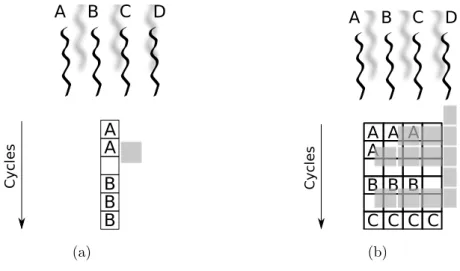
The Blocked Multithreading (BMT) technique implies that a single thread is executed until it reaches a situation that triggers a context switch, usually a long latency operation (Figure 2.2). Compared to IMT technique, a single thread can now be executed at full speed until a context switch occurs. The major drawback of this solution is its limited ability to overcome through-put losses when short stalls occur. Since the CPU issues instruction from a single thread, when a stall is encountered its pipeline must be emptied (or frozen) and must be filled up with the instructions of the new thread, result-ing in a thread context switch of few clock cycles. Because of this start-up overhead, BMT is much more useful for reducing the penalty of high latency operations, where the cost of pipeline refill is negligible compared to the stall time.
2.1. Taxonomy of multithreaded architectures 11 C yc les A B C D A A B B B (a) A B C D C yc les A A A A B B B C C C C (b)
Figure 2.2: Different approaches to Blocked Multithreading, in the case of scalar CPU (a) and superscalar CPU (b)
2.1.3 Simultaneous Multithreading
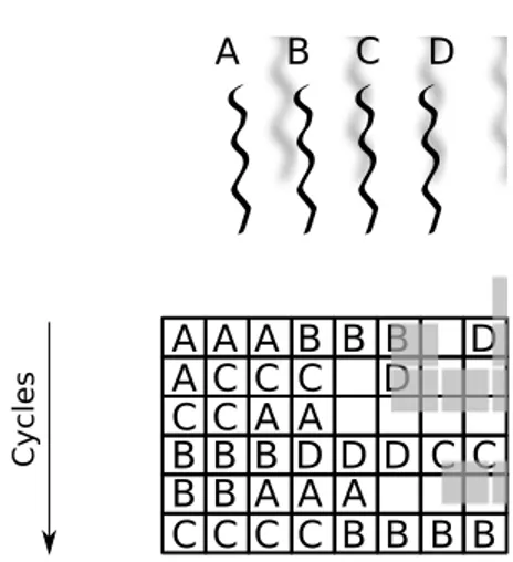
As already mentioned, simple superscalar processors suffer from two inefficien-cies: the limited ability to find ILP in a single program and, consequently, the stalls due to long latency operations. The Simultaneous Multithreading (SMT) approach seeks to overcome the drawback of both superscalar and terleaved/blocked multithreading techniques combining them by issuing in-struction from different threads in the same time slot (Figure 2.3). In this way, latencies occurring in the execution of a single thread are bridged by issuing instruction of the remaining threads.
The key insight that motivates SMT is that modern superscalar processors of-ten have more functional unit parallelism available than a single thread can ef-fectively use. For these reasons, SMT seems to be the most promising approach to multithreading and, until now, the most used in research and commercial solutions.
A B C D C yc les A A A A B B B C C C C B B B D D D D D C C C C C C C B B B B B B A A A A A
Figure 2.3: Example of Simultaneous Multithreading approach: now, instruction of multiple threads are issued in the same clock cycle
2.2 Intel’s Hyper-Threading Technology
Intel’s Hyper-Threading Technology (HT) [13] was firstly introduced in 2002 with Intel’s Xeon and Pentium 4 processors and proposes a two-threaded SMT approach for general purpose CPUs. As already explained, this means that the firmware architecture of an HT CPU is able to maintain informations for two distinct and independent thread contexts. By doing so, HT makes a sin-gle physical processor appears as two logical processors to the operative system.
The processor’s resources fall into three categories:
• replicated: these include general-purpose registers, the Advanced Pro-grammable Interrupt Controller (APIC), the program counter, the in-struction address relocation table (called Inin-struction Translation Looka-side Buffer);
• partitioned: include re-order buffer, load/store buffers and various queues that decouple the major stages of the pipeline from one other. By stati-cally partitioning these resources, if a logical processor is stalled, the other one can continue to make forward progresses. These resources must be recombined in order that, if only one thread is active, it can run at full speed;
2.3. Multithreading in Parallel Computing 13 • shared: comprise caches (Trace Cache, which performs also the tagging
of threads instructions, and data caches), data address relocation table (Data Translation Lookaside Buffer), branch predictors, control logics and execution units. Access to them is handled in a round robin fashion. As highlighted in [16], the primary difference between the HT implementation and the SMT architectures proposed in literature regards the mode of sharing the hardware structures. In fact, SMT researches indicate that virtually all structures are more efficient when dynamically shared, rather than statically partitioned like HT does for some of them. Even if any negative effects of the partitioned approach are minimized with only two hardware contexts, it should be keep in mind that the technique employed by Intel, at least in its first im-plementation, will not scale well to a larger number of hardware contexts.
Regarding the benefits achieved, according to Intel, the first implementation uses only 5% more die area than a comparable non Hyperthreaded processor, but the performance is 15-30% better. Nowadays, Intel’s Hyper-Technology technology is the most available commercially solution for SMT in general purpose CPUs.
2.3 Multithreading in Parallel Computing
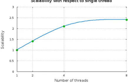
Theoretical and experimental results show that SMT is well suited in a mul-tiprogram context, achieving a scalability that ranges in the interval 1.4-2.4 for a number of threads in the interval 2-8 (Figure 2.4). Parallel applications usually exhibit an high exploitable degree of parallelism and SMT could seems to be a good choice also in this case. Unfortunately, the simple solution of increasing the degree of parallelism allocating more computation threads on the same processor, does not give the expected results. Contention for shared resources, indeed, limits the performance advantages of MT on current SMT processors, thus leading to marginal utilization of multiple hardware threads and even a slowdown due to multithreading.
Figure 2.4: Performance evaluation of multithreading on the standard benchmark suite Spec95 and Splash2
benchmarks, the impact of exploiting Intel’s Hyperthreading (as mentioned, the Intel’s SMT implementation) in a Symmetric Multi Processor (SMP) sys-tem. They conclude that it is not always clear whether it is better to use one or two threads per processor. They show that doubling the degree of parallelism with respect to the traditional SMP (thus having two thread run together on a single processor) there is an average increase in performances of merely 7% and in some cases there is also a slowdown, till 30% in particular benchmarks. This is due to the fact that in this case the threads will have similar character-istics, and so, they will put pressure on the same resources that will become bottleneck. In particular the authors experienced an increasing in:
• cache misses: in an Hyperthreaded processor, L2 cache is shared between the two threads. If the working set of both co-executing threads do not fit in L2 cache then cross-thread cache-line eviction significantly increases the number of misses;
• DTLB misses: in many cases, co-executing threads work on different portions of virtual address space and, therefore, cannot share DTLB entries. This, in turn, results in an effective halving of the data TLB
2.3. Multithreading in Parallel Computing 15 area per thread and, thus, in an increased number of misses.
• stall cycles: the previous considerations and the content for execution units, increase the stall cycles rate (calculated over the total number of execution cycles), that goes up of a factor 3.
In conclusion, how to efficiently exploit multithreading in parallel applications is still unknown. In the literature, many researches suggest the use of co-operating threads to increase the performance of a single thread computation. Speculative precomputation is an example of such techniques and will be briefly discussed in the next section.
The work of this thesis aims to investigate an alternative approach to the problem, by utilizing multithreading to facilitate interprocess communication in parallel applications, by emulating a communication processor when it is not physically available.
2.3.1 Speculative Precomputation
Speculative precomputation (SPR) is a technique to improve single-threaded performance on a multithread architecture. Clearly, such a technique can be also used in the context of parallel applications. It utilizes otherwise idle hard-ware thread contexts to execute helper threads on behalf of the main one. These additional threads, speculatively prefetch data that are going to be used by the main computation thread in the near future, thus hiding mem-ory latency and reducing cache misses. SPR could be thought of as a special prefetch mechanism that effectively targets load instructions that traditionally have been difficulty to handle via prefetching, such as loads that do not exhibit predictable access patterns ([4]).
In brief, implementing SPR consists of the following steps:
1. identify the so called delinquent loads: in many practical cases, only few loads are responsible for the vast majority of cache misses. Their identification is usually done by means of profiling tools;
2. generate code for prefetcher threads: a possible solution is to replicate the original program code and preserve only the backward slices of the target delinquent loads; all other instructions are eliminated;
3. insert synchronizations point between prefetcher and computation threads: this must be done in an accurate way, in order that prefetchers bring right data at the right time.
Results on simulated multithreaded architectures with ideal hardware support (such as multiple contexts, efficient mechanism for thread spawn, special hard-ware for lightweight synchronization between threads) shows that particular SPR techniques can achieve an average 70% of speedup over various bench-marks ([4]). On the other hand, experimental tests conducted on a commercial hyperthreaded platform (that does not have such ideal mechanisms) show that, on a pool of benchmark, SPR achieve speedups between 4% and 34% in half cases, while performs comparably to single threaded execution in the rest ([2]).
CHAPTER
3
Communication in parallel
applications
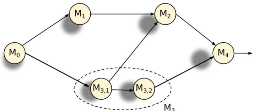
Parallel applications can be expressed by means of computation graphs, whose nodes represent computational modules that cooperate in order to achieve a common goal. Assuming, without loss of generality, a local environment (or message-passing) cooperation model, the edges of the graph will represent com-munication channels that will be used to exchange informations between mod-ules (Figure 3.1). M0 M1 M2 M4 M3,2 M3,1 M3
Figure 3.1: An example of computation graph: each module can be seen as a server or a client with respect to another one. For example M1 is a servant for M0 but a client with
respect to M2. Inter-node parallelism can be exploited to reduce the effect of bottlenecks,
How to study and organize these systems is usually done according to well-known parallelism paradigms: they are schemes of parallel computations that recur in the realization of many real algorithms and applications. Such para-digms are characterized by formal cost models that allow the programmers of parallel applications to evaluate the performance metrics of the single modules and of their graph composition.
Parallel programs, expressed as structured computation graphs via high-level parallel programming tools, are usually compiled in a set of processes, whose cooperation is defined by means of a concurrent programming language. As reference language will be used LC, a simple concurrent language introduced, with didactic purposes, in HPC courses of the master program ([19]). For the moment, it’s important to know that such a language, as any existing message-passing library, is defined according to the general semantics of Hoare’s Com-municating Sequential Processes (CSP). Send and receive commands are the basic interprocess communication primitives provided. As usually, their com-bination has the effect of transferring a message from a sender to a receiver, through a communication channel.
Channels are unidirectional, have a unique name and a type: this is the type of the messages that can be sent over them and the type of the target vari-ables to which received messages can be assigned. They can be symmetric or asymmetric and are characterized by an asynchronous degree k ≥ 0 (k = 0 correspond to the case of synchronous communication).
The compiler of the parallel application has several versions of the runtime support of LC and selects one of them in order to introduce optimizations (e.g. zero copy communication) depending on the application and/or on the underly-ing architecture (e.g. uniprocessor, shared memory multiprocessor, distributed memory multiprocessor, ...). A LC runtime support suitable for interprocess communication in shared memory systems and its implementation details will be discussed in chapter 4.
3.1. Overlapping communication and computation 19 and the benefits of overlapping them with computation will be discussed. Then an architectural support suitable for this scope, the communication processor, is briefly described.
3.1 Overlapping communication and computation
In cost models for parallel paradigms, a fundamental metric is the interprocess communication latency Lcom. This is intended as the mean time needed to exe-cute a complete communication, that is the mean time between the beginning of the send execution and the copy of the message into the target variable, including synchronization and low level scheduling operations. We can define the latency for transmitting a message of L words as:
Lcom(L) = Tsend(L) + Treceive(L)
where Tsend and Treceive are the latencies of the respective operations. In the case of zero copy runtime support, the message is copied directly into the target variables of the receiver, without intermediary copies. Hence, the latency of a receive operation is negligible with respect to the send one, since the receiver runtime support does not perform message copies. Supposing that this optimization is used, the communication latency can be rewritten as:
Lcom(L) = Tsend(L) = Tsetup+ LTtrasm where:
• Tsetup is the average latency of all the actions that are independent of the message length: synchronization, manipulation of structures of the runtime support, low level scheduling;
• Ttrasm is the latency to copy one word of the message.
Both of them depend on the concrete architecture and runtime support imple-mentation. Typical order of magnitude for shared memory architectures are Tsetup= 103÷ 104 τ and Ttrasm= 102 ÷ 103 τ .
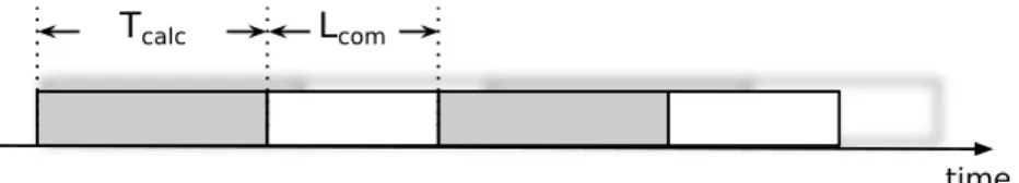
Can parallel applications benefit of overlapping communication and compu-tation? Consider a generic parallel application and, in particular, one of its modules that operates on stream. Suppose that this module during its life cycle alternates computation and communication phases: this is a typical si-tuation in many parallel paradigms that operate on streams. Typically, these two phases follow each other sequentially (Figure 3.2). In this case the service
Tcalc Lcom
time
Figure 3.2: Non overlapping case: gray boxes identify calculus phases, white boxes commu-nication ones. In such a situation no overlapping between calculus and commucommu-nication is present
time of this module will be increased by the communication latency because it is entirely paid, resulting in:
T = Tcalc+ Lcom
Consider now the case in which proper architectural supports exist (i.e. a communication processor) to which the execution of an asynchronous send could be delegated. In this case the module, once the primitive is offloaded to the communication processor, can start the following calculus phase without waiting; in the meanwhile and in parallel the communication is performed. In general this allow to hide (at least in part) the communication latency (Figure 3.3). Denoting with Tcom the average communication time not overlapped with internal communication, the module service time can be written as
T = Tcalc+ Tcom = max(Tcalc, Lcom)
resulting in a clear advantage with respect to the previous case if Lcom is not negligible with respect to Tcalc. The module latency, instead, is always affected by the communication latency.
3.2. Communication processor 21 time Tcom Lcom time Tcalc
Figure 3.3: In this situation there is the possibility to overlap communications and com-putation. In the first case, the communication latency is fully masked by the calculation one (Tcalc ≥ Lcom). In the second case, the most general one, calculation is only partially
overlapped to communication
3.2 Communication processor
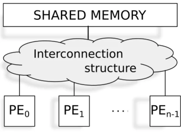
Shared memory system are MIMD (Multiple Instruction Stream Multiple Data Stream) general purpose architectures, characterized by a certain number of processing nodes (n, typically homogeneous), that share the main memory physical space and are connected each other and with the main memory by an interconnection structure (Figure 3.4).
SHARED MEMORY
Interconnection
structure
PE
0PE
1PE
n-1Figure 3.4: Structure of a shared memory system: memory and processing nodes are con-nected each other via an interconnection structure, usually of limited degree
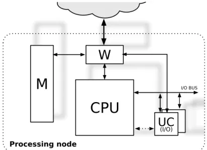
The general structure of a processor node is depicted in Figure 3.5. This is
CPU
W
M
UC
(I/O) I/O BUS Processing nodeFigure 3.5: The internal structure of a processing node
characterized by:
• CPU: processing nodes are usually based on general-purpose, commercial off-the-shelf CPUs or computers. This is true also for multicore (or Chip Multi Processor, CMP) architectures, which often integrate existing CPUs into the same chip. An off-the-shelf CPU chip is connected to the “rest of the world” through its primitive external interfaces (e.g. Memory Interface, I/O Bus). Such CPUs should be, in any case, suitable to be immersed into a multiprocessor system: for example, should be capable to generate proper physical addresses for addressing the whole shared memory space;
• local memory and I/O units;
• node interface unit (W): this unit is in charge of interfacing the processing node with the rest of the system. In this way, existing CPU can be used thanks to the fact that W masks to the CPU the structure of the shared memory and interconnection network;
3.2. Communication processor 23 • communication unit (UC): it is provided for direct interprocessor
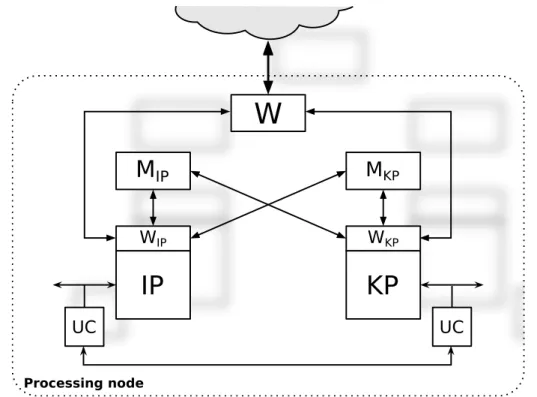
com-munications support, usually performed for processor synchronization (involved in locking mechanism) and process low-level scheduling. As already said, to allow overlapping between computation and communication there is the need of proper architectural supports, such as a communication processor. The structure of a processing node could evolve as illustrated in Figure 3.6.
IP
KP
WIP WKP UC UC Processing nodeM
IPM
KPW
Figure 3.6: The internal structure of a processing node with a communication processor: processing node itself can now be considered as a shared memory multiprocessor
Every node has now two processors: the communication processor (KP) and the main one (IP) with their respective local memories and I/O units. KP is dedicated, or specialized, to the execution of the runtime support of LC and, in particular, of the send primitive. The delegation of the send is performed by passing to KP the information required to execute the primitive (typically the identification of the channel and a reference to the message): these infor-mations are contained into a data structure prepared by IP, whose reference is
passed to KP via I/O (i.e. via a communication UC-UC).
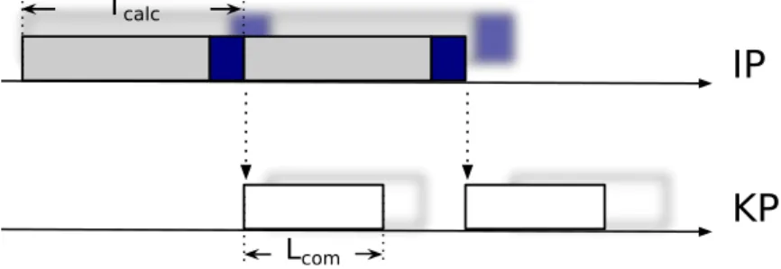
Usually, not the entire execution of the send is delegated to KP, but some run-time support related functionalities are still performed by IP. As an example consider the send semantics: when the message is copied, if the asynchrony de-gree becomes saturated the sender process must be suspended. If IP delegates the send execution entirely to KP, then some complications are introduced in the send implementation because of the management of the waiting state of the sender process. A simple solution to the problem is that IP itself verifies the asynchrony degree of the channel, after the send delegation (clearly this control will not be performed again by KP), suspending the sender process if necessary. The initial phase executed by IP is now not overlapped to the in-ternal calculation. In the interprocess communication cost model, the latency
IP
KP
Tcalc
Lcom
Figure 3.7: Send delegation from IP to KP; blue boxes represent part of the send runtime support executed by IP
of this phase must be included in the Tcalc parameter (Figure 3.7).
3.2.1 Commercial implementation of communication processors
A concrete example of application of the communication processor can be found in the Intel Paragon XP/S, first shipped in the 1992 ([5]). Even if it is a dis-tributed memory architecture, the same idea till now discussed is applied. In the Intel Paragon systems up to 2048 processing nodes are connected in a 2D mesh: each of them is a shared memory multiprocessor, with two Intel i860XP RISC processors, 16-32 Megabytes of local memory and a Network Interface Card. One of the processors is designated as communication processor and
3.2. Communication processor 25 handle the message-passing primitives, while the other is used as a compute processor for general computing, exactly as illustrated before.
In general, although it is possible to realize KP with the same architecture of IP, the recent trend is to design it as an input-output coprocessor, specialized at the firmware level, sharing memory with IP through DMA and Memory Mapped I/O. In particular, this kind of implementation is adopted when the communication processor is provided inside the interconnection network box. This is the case of specialized networks for HPC, such as Quadrics, Myrinet and Infiniband.
Taking into account the case of Myrinet ([3]), its Myricom/PCI network in-terface card (Figure 3.8) is characterized by a a communication processor, a local memory and two DMA engines responsible, respectively, for data transfer from host memory to local memory and from local memory to network. The
HOST
HOST
DMA KP
NETW DMA
PCI bus network
LOCAL MEMORY
Figure 3.8: Basic structure of the Myricom/PCI network interface card
former is responsible for the execution of message-passing protocol once proper delegation is performed by the host node.
CHAPTER
4
Multithreaded support to
interprocess communication
In the previous chapter has been discussed how the parallel applications can benefit of communication-computation overlap. At this point one wants to understand if and how it is possible, in a multithreaded and shared memory architecture, emulate the facility of a communication processor when it is not physically available. This chapter deals with this problem, implementing a minimal core of the concurrent language LC that provides this feature. The approach adopted is to associate to each process/thread of the parallel applica-tion (from now on will be referred as worker thread ) a thread that is in charge of executing the send primitive (communicator thread ) following a philosophy similar to the IP-KP case.
Although the goal is quite circumscribed, many of the issues that will be ad-dressed are common in approaching this kind of problem, independently from the concurrent language used.
The chapter is structured in the following way:
1. programming in multithreaded architectures: measure to be adopted in programming, for efficiently exploit these kinds of systems, are briefly
discussed;
2. inter-thread synchronization: the problem of how efficiently synchroniz-ing two threads, with particular attention to the specific work context, is approached;
3. LC runtime support : the runtime support of a minimal core of the con-current language in shared memory architectures is introduced;
4. communicator implementation: finally, how to extend the traditional sup-port of LC for emulating a communication processor is described. Through the rest of the thesis, as reference architecture will be considered a shared memory multiprocessor with Hyper-threading technology, whose struc-ture is shown in Figure 4.1. It is composed of 2 CPUs Intel Xeon E5520
Core 0 Core 1 Core 2 Core 3 Core 4 Core 5 Core 6 Core 7 L1 L1 L1 L1 L1 L1 L1 L1 L2 L2 L2 L2 L2 L2 L2 L2
Level 3 cache Level 3 cache
IMC QPI QPI IMC
SHARED MEMORY
Figure 4.1: Internal structure of the reference architecture: the Integrated Memory Controller (IMC) and Quick Path Interconnect (QPI) constitute the interconnection structure of the system
(running at 2.27 GHz), each of them with four physical cores supporting the Hyper-threading technology (2-way Simultaneous Multithreading). Level one and level two cache (respectively of 32 and 256 Kb) are private for each core,
4.1. Programming in multithreaded architectures 29 while the level three cache (8 Mb) is shared by all the four cores of a CPU. The machine is equipped with 12 Gb of RAM and runs a GNU/Linux operating system, based on the Linux Kernel 3.0.
4.1 Programming in multithreaded architectures
In the case of a multithreaded architecture, a thread is viewed as a firmware level supported thread which can be a single process, a user defined thread, a compiler-generated thread such as micro or nanothreads.
Since the reference environment is a Linux-based operating system, the obvi-ous solution seemed to exploit multithreaded architecture through used-defined threads created with the features offered by the Native POSIX Thread Library (NPTL, compliant with POSIX standards). With the POSIX Threads, a pro-cess can have multiple threads each of which has its own flow of control and its own stack. Everything else about the process, including global data, heap and resources, is shared.
Even if the methodologies applied are the usual of multithreaded programming, here the application programmer (or, as in this particular case, the runtime support designer) should be well aware that he/she is working on a multi-threaded architecture and how it is organized.
As explained in sect. 2.2, Hyper-threading technology makes the single two-threaded physical processor/core appears as two logical processors (referred as siblings processors), each of them identified by a unique ID. HT-aware Linux schedulers are clever enough to manage this situation efficiently, for example trying to schedule threads/processes on sibling processors only if it is strictly necessary, taking into account that the majority of the resources is partitioned or shared between them. Nevertheless, in programming the runtime support of LC with communication processor facilities there are more stringent require-ments, for example assuring that the worker and communicator threads run on two sibling processors to better exploit the cache (since the low levels are shared between sibling processors). This is usually done by providing directives
to the scheduler regarding the binding thread-logical processor, the so called processor affinity. NPTL provides proper function for this purpose, such as the pthread setaffinity np().
The only thing that the support user must know is the processors topology, that indicates the association between logical and physical processors. In Linux systems such informations are published through the sys pseudo file system ([7]). For the testing architecture, this association is sketched in Figure 4.2
Physical core
Physical package
0
2
4 6
1
3
5
7
8 10 12 14
9 11 13 15
Figure 4.2: Processors topology of the reference architecture: there are two physical CPU (also called packages) each of which has four physical cores. The numbers represent the ID of a logical processor associated by the operative system; ID on the same column identify sibling logical processors
4.2 Inter-thread synchronization mechanisms
In the working scenario, the communicator thread has to wait, even for a large period of time, that a send is delegated to it by the worker thread; there-fore, there is the need for inter-thread synchronization mechanisms provided in the form of classical wait/signal primitives. Considering the asymmet-ric workload that characterizes these two threads and, especially, the context of an Hyper-threaded machine where many of the computational resources are dynamically shared or statically partitioned, such mechanisms must have prop-erties of high responsiveness and lightweightness.
In the literature, proper hardware extensions have been proposed to meet these requirement (consider as an example the lock-box introduced in [17]), while many brand new commercial products (such as the IBM wirespeed processor)
4.2. Inter-thread synchronization mechanisms 31 provide appropriate synchronization primitives.
An Hyper-threaded processor does not provide such mechanisms for low-latency and resource-friendly synchronization directly at the firmware level.
In the following, classical method (POSIX mechanisms and spin locks) and a new one (proposed in [1] and based on proper Intel’s assembler instructions) for synchronizing two threads are discussed. In conclusion, an evaluation of such mechanisms is presented. Except where indicated otherwise, the code that will be shown is written in a C-like pseudocode.
4.2.1 POSIX
POSIX standard provides well-known mechanisms for synchronizing threads. To signal and wait for a condition, three things are necessary: a mutex M , a condition variable C and a predicate P . The first two are proper data structure offered by POSIX Threads; the predicate depends from the particular context of application. Primitives that work on condition variables must be called in critical sections, as shown in the example.
Thread A : mutex lock (M) ; <... > c o n d s i g n a l (C) ; mutex unlock (M) ; Thread B : mutex lock (M) ; w h i l e ( ! P) c o n d w a i t ( C ,M) ; <... > mutex unlock (M) ;
The call at cond wait() do not imply busy-waiting: it actually releases the as-sociated mutex, causes the thread to be descheduled (passing in waiting state) and, assuming that there is no other runnable thread, the processor resources previously occupied are released in favour of the worker thread.
Latest versions of the NPTL Library makes use of futexes (Fast User muTEX), a mechanism provided by the Linux Kernel (2.6 or greater) as building block
for fast userspace locking. In this case, multiple threads communicate locking state through shared memory regions and atomic operations; a futex based lock works in user space unless there is a lock contention ([10]). In this case, system calls are required to wake up a process or to put another one into waiting state. Even if this solution could save many user-kernel-user space switches compared with old implementations, it should be considered that some overhead is unavoidable due to the presence of system calls.
4.2.2 Spin lock
Synchronization primitives based on spin lock have been commonplace in tra-ditional multiprocessor systems, due to their simple implementation and high responsiveness; unlike to the previous solution, they imply busy waiting. In the case of spin lock, the lock variable can be a simple boolean that indicates whether the lock is held by someone. Each processor repeatedly use an atomic test-and-set or exchange instruction in attempt to change the flag from false to true, thereby acquiring the lock. A processor releases the lock by setting it to false.
The principal shortcoming of this first version is contention for the flag: each waiting processor accesses the single shared flag as frequently as possible us-ing the indicated instructions. This can be particularly expensive on cache-coherent processors, since each execution of such instructions can cause a cache line invalidation (resulting in a ping-pong effect). A simple modification to the presented algorithm is to use a test-and-set instruction only when a previous read indicates that this can succeed.
In modern out-of-order processors a spin loop is dynamically unrolled multiple times since there are no data dependencies and the branch that it contains can be easily predicted. In an Hyper-threaded environment, a synchronization primitive based on spin locks can incurs significant performance penalty since the spinning thread, even though not performing any useful work, inserts a significant number of instructions that compete with other threads executing
4.2. Inter-thread synchronization mechanisms 33 on the sibling logical processor (the worker thread in this context) causing a slow-down of both of them.
Intel recommends the use of PAUSE instruction in spin loops ([12]): these in-struction introduces a slight delay in the loop and de-pipelines its execution, preventing it from aggressively consume processor resources. The cost of spin-ning, however, is reduced but not entirely eliminated, because the resources designated to be statically partitioned are not released by the spinning thread. Considering the use of the PAUSE instruction, a simple spin lock, written in assembler language, is the one reported in Listing 4.1.
SLOCK : mov [ LV ] , eax cmp 0 , eax
j e GET LOCK pause
goto SLOCK GET LOCK : mov 1 , eax
xchg [ LV ] , eax cmp 0 , eax
j n e SLOCK
Listing 4.1: Spin lock assembler implementation using the pause instruction. LV represents the address of the locking flag
Spin locks can constitute a building block for simple synchronization primitives. Spin lock itself can be used as primitive for the access in critical sections while a condition variable can be implemented via a boolean flag. Maintaining a style similar to the POSIX standards, the signalling and waiting procedures must be called into a critical section. The former simply set the flag; the latter first of all resets the flag and then, cyclically, check it values, releasing the lock if founded still unset. The resulting wait primitive is shown in Listing 4.2.
b o o l n o t i f i e d =f a l s e ; c=UNSYNCHR VALUE ; // r e s e t t h e f l a g s p i n u n l o c k ( l ) ; // f r e e t h e l o c k v a r i a b l e do { s p i n l o c k ( l ) ; // l o c k i f ( c==SYNCHR VALUE) // t h e p a r t n e r n o t i f i e d
n o t i f i e d =t r u e ; e l s e
s p i n u n l o c k ( l ) ; // u n l o c k and l o o p
} while ( ! n o t i f i e d ) ;
Listing 4.2: Wait primitive: c represents the condition variable. It must be called into a critical section
Clearly, the behaviour is slightly different compared to the POSIX case: • a condition variable can be used to synchronize entities only in a
”one-way” fashion. This means that if it used by thread A to signal a condition to thread B then it cannot be used to synchronize these entities in the opposite way, otherwise dead-locks can occur;
• since wait and locking primitives require busy waiting, no fairness is guaranteed to the contenders. Thereby, it is better to use this solution to synchronize only two entities (like in the study case).
4.2.3 MONITOR/MWAIT instructions
MONITOR and MWAIT are two assembler instructions introduced with the Intel’s Prescott architecture. The MONITOR instruction sets up a memory address that is monitored for write activities. MWAIT, instead, places the calling processor in a ”performance-optimized” state (which may vary between different implemen-tations) until a write to the monitored region occurs [12]. MWAIT still causes a busy waiting but behaves as a NOP and execution continues at the next in-struction in the execution stream. Moreover, on a Hyper-threaded processor, a thread that calls MWAIT causes its logical processor to relinquish all its shared and partitioned resources.
The address provided to MONITOR instruction effectively defines an address range, within which a store will cause the thread blocked to the MWAIT to wake up. Thus, to avoid missed wake ups, the data structure that will be used as condition variable must fit within the smallest monitor line size and must be
4.2. Inter-thread synchronization mechanisms 35 properly aligned so that it does not cross this boundary. Otherwise, the pro-cessor may not wake up after a write intended to trigger an exit from MWAIT. Similarly, write operations not intended to cause an exit from the optimized state should not write to any location within the monitored range. In order to avoid false wake ups the data structure should be padded to the largest mon-itor line size. Both of this parameters (smallest and larger monmon-itor line size) are architecture dependent and should be properly checked; in the reference system are equal to 64 bytes.
Furthermore, multiple events, other than a write to the triggering address range, can cause a processor that executed MWAIT to wake up, such as inter-rupts or context switches. This means that, after wake up, the value stored in the triggering address should be checked and, if necessary, return in a waiting state: therefore MONITOR/MWAIT need to be executed in a loop.
In their initial implementation, MONITOR and MWAIT instructions are allowed to be executed only in kernel space, with the maximum privilege level1. Therefore, in order to be able to implement synchronization primitives based on these two instructions, there are two possible solutions:
• extend the Linux Kernel with a pair of system calls through which access to these instructions is granted;
• run the program that use them directly at kernel level.
The second option has been chosen as best representing a probable future si-tuation where these instructions are released by Intel to be executed in user level, avoiding the overhead that the system call will have introduced. To run the entire programs in kernel mode, a proper patch of the Linux Kernel will be used (Kernel Mode Linux, [15]).
1Actually, during the study of this instructions, some machines were found in the
com-puter center facility of the university, based on Pentium 4 HT (the first commercially available processor with Hyper-threading technology) that can run this instruction also at user level
As before, simple synchronization primitives based on these instructions are provided. Access to critical sections is still granted through spin locks. The condition variable is now a vector of 64 bytes that has to be properly aligned on memory. The sketch of the wait primitive, that addresses all the previously stated problem, is shown in Listing 4.3.
b o o l n o t i f i e d =f a l s e ; c=UNSYNCHR VALUE ; do // m o n i t o r / mwait c y c l e { mm monitor (&c , 0 , 0 ) ; // s e t t h e m o n i t o r r e g i o n s p i n u n l o c k ( l ) ; mm mwait ( 0 , 0 ) ; // w a i t f o r a s t o r e on i t s p i n l o c k ( l ) ; // a c c e s s t o t h e c o n d i t i o n v a r i a b l e and c h e c k i f ( c==SYNCHR VALUE) // t h e p a r t n e r n o t i f i e d n o t i f i e d =t r u e ; // o t h e r w i s e l o o p } while ( ! n o t i f i e d ) ;
Listing 4.3: Wait primitive based on MONITOR/MWAIT instructions: c represent the condition variable. mm monitor and mm mwait are the GCC intrinsics counterparts of the MONITOR/MWAIT instructions
The considerations done for the primitives based on spin lock, are valid also for this case.
4.2.4 Evaluation of the synchronization mechanisms
For comparing the illustrated synchronization mechanisms a proper test sce-nario has been set up. There are two threads allocated on two sibling proces-sors: the first one (worker thread ) performs, cyclically, heavy calculus in one case and, in a second one, make also random accesses to a data structure in order to generate a large amount of cache faults. The second (waiting thread ) just waits until notified by the former each time that a calculus cycle is com-pleted.
primi-4.2. Inter-thread synchronization mechanisms 37 tive.
The gathered metrics of interest are:
• T : the completion time of the worker thread: the larger this time is, the more disturbing is the co-existence of the waiting thread on the physical processor;
• Tcall: the time (measured in processor cycles) that the worker thread spends in invoking the notification primitive;
• Twakeup: the time (measured in processor cycles) between the notification to the waiting thread and the moment that it is actually awakened. Results of the two tests ran on the reference architecture are shown in Table 4.1 and Table 4.2.
P rimitive T (msec) Tcall(cycles) Twake(cycles) Spinlock 4420.5 193 318
MONITOR/MWAIT 2934.12 131 815 P osix 2861.5 3918 162094
Table 4.1: Test case with only calculus
P rimitive T (msec) Tcall(cycles) Twake(cycles) Spinlock 37881.101 602 779
MONITOR/MWAIT 36721.699 719 1701 P osix 35472.199 9640 72154
Table 4.2: Test case with calculus and cache faults
As expected, spin lock based primitives provide minimum response time and call overhead (comparable with the one exposed by MONITOR/MWAIT) but they are the most aggressive in term of resource consumption. In the first test case, on average the spinning thread decelerates the worker thread of more than 50% compared with the other two solutions. This difference decreases in the second test case, resulting in a slowdown of only 4%: this is probably due to
the fact that the latencies introduced by cache faults allow to amortize the additional workload caused by the waiting thread. POSIX based primitives present the worst wakeup and call times due to the passage at kernel level and rescheduling of waiting thread. However they present a completion time that is less compared to the one obtained with MONITOR/MWAIT primitives, that perform on average 3% worse. This indicates that the “performance-optimized” state of MWAIT still introduces some impairments on the sibling thread.
As stated in Intel’s documentation, this state is implementation dependent. In fact, the same tests run on a newer Intel’s processor compared to the reference one (Intel Core i7-2677M dual core, running at 1.80GHz, 32 Kb for L1 cache and 256Kb for L2 cache, same operative system of the reference architecture) show that the difference between the completion time obtained with the POSIX mechanisms with respect to the one resulting by the usage of MONITOR/MWAIT based primitives decreases of one order of magnitude (Table 4.3 and Table 4.4).
P rimitive T (msec) Tcall(cycles) Twake(cycles) Spinlock 3662.8 186 261
MONITOR/MWAIT 2381.6 62 615 P osix 2358.899 1421 69803
Table 4.3: Test case with only calculus
P rimitive T (msec) Tcall(cycles) Twake(cycles) Spinlock 29656.099 658 744
MONITOR/MWAIT 28613.599 561 1327 P osix 28525.3 8452 96752
Table 4.4: Test case with calculus and cache faults
Hopefully this gap will become smaller and smaller as new architectures re-fine these instructions. Regarding the false wake ups caused by event external to the computation, it has been noticed that they are exclusively due to the interrupts send by the system timer to the processor for indicating that the time quantum is expired; in any case, this don’t impact on the completion time.
4.3. Runtime support of LC 39 In conclusion, it is clear that the spin lock based synchronization mechanisms are not suitable for synchronizing two threads running on the two sibling pro-cessors. On the other hand, a single winner from the comparison between POSIX mechanisms and MONITOR/MWAIT based synchronization primitives can not be determined both for the simplicity of the test cases considered (which are, in any case, extreme situations) and, as pointed out, because these instruc-tions seem to be subject to potential future improvements. For this reason, the support user will be allowed to chose which one use. In chapter 5, tests will be performed with both type of primitives. Moreover, given the generality of this mechanisms, they will not used only in the case of inter-thread synchronization but also to regulate the access to the runtime support data structures.
4.3 Runtime support of LC
The minimal core of LC that will be implemented refers to the case of sym-metric, synchronous or asynchronous, deterministic channel (i.e. not referred in alternative commands) for shared memory architectures, with zero copy op-timization. The interface offered to the user is inherited by a previous work of the research group ([8]) and it is maintained for compatibility reasons. Since in the case of communication processor the interest is focused on asynchronous communications, the runtime support for this kind of communication is now discussed. The synchronous case is obtained with some minor modifications.
4.3.1 Zero copy optimization and shared memory segment
The zero copy technique allows the sender to copy a message directly into the target variable of the receiver without copies in intermediary data structures. The number of copies is just one, i.e. the minimum independently of the re-ceiver progress state (zero copy stands for zero additional copy). This means that the processes involved into the communication must share part of their virtual memory, in particular the target variables are shared objects
them-selves.
Moreover, one objective of this work is to design the runtime library in a proper way to be executed in the user space. In this way the additional over-head caused by the execution of a language primitive in supervisor (or kernel) state is saved.
Unix-based operative systems offer a basic mechanism for sharing memory between different processes: the XSI Shared Memory Segment. A segment is created by one process and, subsequently, written and read by any number of processes that acquire it in their address spaces. This means that the logical addresses, generated by the different processes that operate on the segment, will be relocated to the same physical addresses. Once that the process finishes to work with it, it is detatched from its virtual memory and, when none of the processes is willing to use it, it is finally marked to be destroyed. The memory segment is referred (hence shared and acquired) by a key that unequivocally identifies it in the system.
A peculiar characteristic, that will influence some implementation choices, is that a process can not dynamically share, via an XSI memory segment, an already allocated portion of its virtual memory. In the case of the runtime support for LC, this implies that a receiver can not dynamically share the target variables. These must be created at channel creation time by allocating the necessary space into a memory segment that will be shared by sender and receiver.
4.3.2 Channel descriptor
The basic data structure of the runtime support is the channel descriptor that will contains all the informations necessary for an efficient implementation of LC functionalities. Along with the target variables, this structure is shared by sender and receiver. For consistency reasons, the procedures that manipulate it must be executed in an indivisible way. This requirement is achieved by means of locking primitives, such as the ones previously discussed. Moreover
4.3. Runtime support of LC 41 the communication primitives could require some synchronization between the involved entities. In particular:
• when executing a receive, if the communication channel does not contains any message, the receiver must wait until a send is executed;
• when executing a send, if the communication channel is full (the asyn-chrony degree has been reached), the sender must wait until a receive is executed.
Depending of what type of synchronization primitive is used, these situa-tions could imply busy waiting (such as in the case of MONITOR/MWAIT) or not (POSIX mechanisms).
The type of the channel is specified at creation time, therefore the dimension of the target variables is known and fixed. If the asynchrony degree is equal to K, K + 1 target variables, handled as a circular vector, will be created and shared between sender and receiver. The solution N = K + 1 avoids that the sender process re-executes the send primitive once that the asynchrony degree is reached: it completes the actual send operation and then is suspended. In this way, once waked-up, it is resumed at the return logical address of the send procedure.
By the definition of the zero copy method, the receiver process works directly on the target variable instances (without copying them). Therefore, a critical race could occurs when the sender tries to copy a message into a target variable and the receiver is still utilizing it. To overcome this problem, a simple solution is to allocate J additional target variables. J is chosen at channel creation time (J ≥ 0) and this results in having a total of N = K + J + 1 target variables; in many practical cases, J is equal to 1. The send procedure will copy the messages in this N variables, handling them as a circular buffer, respecting the asynchrony degree constraint. On the other hand, the receiver can execute at most J receive and, simultaneously, use the respective target variables, being sure that the execution of a send will not overwrite their content.
each target variable that indicates whether or not it is safe to overwrite it. Thus the sender process will now be suspended also if the validity bit of the target variable to which this message must be copied is set to false. On the re-ceiver side a proper primitive (e.g. set validity bit()) must be provided in order to allow the receiver process to indicate that it is no more willing to utilize a specific target variable.
Even if a validity bit mechanism (with a slightly different semantics) has to be included in the channel descriptor for consistency reasons that will be clear in the next section, the solution of the additional J target variables has been chosen, mainly for reasons of backward compatibility.
Taking into account these considerations, in the case of asynchronous channel (the synchronous case is simply derived from this one) the channel descriptor data structure contains:
• lock variable: used to assure the exclusive access to the descriptor; it will be used by all the procedures that intend to manipulate the data structure;
• key: the identifier of the shared memory segment that contains this chan-nel descriptor;
• condition variable: used for synchronizing sender and receiver processes; if necessary, as in the case of MONITOR/MWAIT based synchronization prim-itives, two condition variables are present;
• size: the dimension (bytes) of the messages transferred through this chan-nel;
• messages: the number of messages currently present into the channel; • K, J: respectively the asynchrony degree and the number of additional
target variables;
• buffer infos: insertion and extraction pointer for the circular vector of target variables; they assume relative values, that is between 0 and N ,
4.3. Runtime support of LC 43 indicating a position within the buffer.
As can be seen, for implementation reasons, the vector of target variables and the vector of the respective validity bits are kept outside the channel descriptor. However they are allocated in the same memory segment of the channel de-scriptor, contiguously to it. In this way, only one memory segment per channel is necessary and, each time that an operation on the buffer (and, consequently, on the validity bits) must be performed, the address of the interested target variable can be easily computed knowing the value of the current insertion/ex-traction pointers, the size of the channel descriptor data structure and the base address of the memory segment. Figure 4.3 shows the internal organization of a memory segment.
Channel
descriptor
Target
variables
Validity
bits
BA BA + sizeof(c h) BA+s izeof(c h) + + (K+J+1 )sizeFigure 4.3: Shared memory segment organization: supposing that it is allocated into the virtual memory of a process starting from a base address BA, the addresses of all the interesting structures can be easily computed