POLITECNICO DI MILANO
Department of Industrial and Information Engineering
Division of Automation and Control Engineering
Master’s Degree in Automation and Control Engineering
Analytical Analysis of 3kV DC Railway
Regenerative Braking Energy Storage System with
Current Controlled DC-DC Bidirectional
Converters
Supervisor Prof. Francesco Castelli Dezza
Master Thesis of:
Qasim Ali, Amjad
Personal Code: 877630
Muhammad Sajid, Imran
Personal Code: 842393
Analytical Analysis of 3kV DC Railway
Regenerative Braking Energy Storage System with
Current Controlled DC-DC Bidirectional
Converters
Energy Storage Options, Software Implementation & Simulation, ROI By
Qasim Ali Amjad Muhammad Sajid Imran
Supervisor
Prof. Francesco Castelli Dezza
Department of Industrial and Information Engineering
Division of Automation and Control Engineering
POLITECNICO DI MILANO Milano, Italia, 2018
This work is dedicated to my parents who always believed in my
abilities to do better for mankind.
Qasim Ali
This work is dedicated to my parents and to my wife. For their
endless Love, Support and Encouragement.
Abstract
Analytical and Cost Analysis of 3kV DC Railway Regenerative Braking Energy Storage System with Current Controlled DC-DC Bidirectional Converters
Energy Storage Options, Software Implementation & Simulation, ROI.
Hefty amount of regenerative braking energy in trains is wasted in already installed trains mainly due to their old infrastructure or mismanagement of train stations. One solution provided as the base of this thesis is to implement an active bi-directional electrical substation to send this energy back to the grid but there are many commercial and corporate problems in doing so. An energy storage system is a viable option to store this energy and then utilizes it some other time increasing the efficiency of the railway system.
A DC-DC bidirectional converter is designed for this purpose; its properties differ for different storage devices such as a fly wheel or a super capacitor. We used a commercially available supercapacitor and designed our converter with a current control scheme for deciding the direction of power flow to or from the supercapacitor. Fly wheel and supercapacitors (from now onwards SC) are also discussed for their parameters and properties which make them feasible for such applications.
We implemented the Matlab Simulink model using the real time data for its designing and then also studied some cases to understand the effect of storage system on the system, such as minimizing the affective peak load from the utility. Train model for braking energy storage will also be discussed for different load and braking scenarios forming our model to be of a complete electric substation with energy storage banks in the form of SC.
The fact that this system costs a lot marks a question of its return of investment. This thesis suggested a pattern for its cost calculation and also about the energy utilization increasing the efficiency of the system and returning of the capital for fly wheel and the supercapacitors.
Key words: Regenerative braking, Bi-directional DC-DC Converter, Supercapacitors, Flywheel, Converter Cascading, Train model and Return of investment.
Acknowledgement
First and foremost, I would like to thank the Almighty God to bless me with an opportunity to pursue the academic path I wished.
I would like to express my sincere gratitude to Professor Engr. Francesco Castelli Dezza for his guide lines during my thesis and sparing his valuable time for continuous follow up to keep me in the right direction to achieve the desired targets.
I would also like to express heartiest indebtedness to Engr. Marco Mauri for his deep interest in my thesis and providing me with all his knowledge and time to make this activity a reality. I would like to thank my parents for their continuous believe and support in all fields of my life, for motivating me through ups and downs, my siblings and colleagues who were my international family away from home and were always present to my needs, mutual support and the beautiful moments shared during these years.
Finally, I would also like to thank Politecnico Di Milano and its academic and organizational staff for humble dealing in all aspects with international students and for providing me one of the life time chance to learn from one of the best teachers in the world.
i
Table of Contents
1. INTRODUCTION ... 1
1.1. BACKGROUND OF THE THESIS ... 1
1.2. PURPOSE OF THE THESIS ... 2
1.3. OUTLINE OF THE THESIS ... 3
2. RAILWAY TRACTION AND BRAKING TECHNOLOGY ... 4
2.1. TRACTION SYSTEMS OVER THE TIME ... 4
2.2. TYPES OF RAILWAYS TRACTION SYSTEMS ... 5
2.3. TRAIN MOVEMENT AND PERFORMANCE CALCULATION ... 7
2.4. BRAKING ENERGY ... 9 2.4.1. ENERGY INTENSIVE ... 9 2.4.2. POWER INTENSIVE ... 9 2.5. TRACTION MOTORS ... 10 2.5.1. DCMOTORS ... 10 2.6. ELECTRIC BRAKING ... 13 2.6.1. DYNAMIC BRAKING ... 14 2.6.2. PLUGGING ... 15 2.6.3. REGENERATIVE BRAKING ... 15
2.7. REGENERATIVE BRAKING IN RAILWAY SYSTEM ... 17
3. REQUIREMENTS FOR REGENERATIVE BRAKING ENERGY STORAGE IN RAILWAY SYSTEMS ... 21
3.1. RAIL REQUIREMENTS FOR STORAGE SYSTEM ... 21
3.1.1. HEADWAY AND DURATION OF OPERATION ... 22
3.1.2. VOLTAGE,POWER AND ENERGY CAPACITY ... 22
3.1.3. CONTROLS,ENERGY MANAGEMENT AND DIAGNOSTICS ... 23
3.1.4. LOCATION,AMBIENT CONDITIONS AND AUXILIARIES ... 24
3.1.5. RELIABILITY AND MAINTENANCE ... 24
ii
4. ENERGY STORAGE DEVICES ... 26
4.1. FLYWHEELS AS MECHANICAL ENERGY STORAGE DEVICES ... 26
4.1.1. STRUCTURE AND COMPONENTS OF A FLYWHEEL STORAGE SYSTEM ... 28
4.2. SUPERCONDUCTING MAGNETS SMES ... 29
4.2.1. COMPONENTS OF SMESSYSTEM ... 29
4.3. SUPERCAPACITORS ... 31
4.3.1. OVERVIEW OF CAPACITORS ... 31
4.3.2. SUPER CAPACITORS ... 33
4.4. AGE AND LIFE TIME ESTIMATION OF SUPERCAPACITORS ... 35
4.4.1. EXPECTED LIFETIME ... 35
4.4.2. STATE OF CHARGE ... 37
5. DC-DC CONVERTER ... 39
5.1. INTRODUCTION TO DC-DCCONVERTER ... 40
5.1.1. STEP DOWN BUCK CONVERTER ... 40
5.1.2. STEP UP BOOST CONVERTER ... 42
5.1.3. BUCK-BOOST CONVERTER ... 43
5.2. DC-DCBIDIRECTIONAL CONVERTERS ... 44
5.3. MULTILEVEL DC/DCCONVERTER ... 46
5.3.1. CASCADED BUCK BIDIRECTIONAL CONVERTER ... 46
5.3.2. CASCADED BOOST BIDIRECTIONAL CONVERTER ... 47
5.3.3. MODULAR MULTILEVEL DC/DCCONVERTER ... 48
6. MODELLING AND SOFTWARE IMPLEMENTATION ... 51
6.1. COMPLETE SYSTEM’S OVERVIEW ... 51
6.2. INNOVATIVE RAILWAY ERSAPPLICATION ... 51
6.2.1. CONFIGURATION OF A SUBSTATION: ... 53
6.2.2. SYSTEM UNDER CONSIDERATION ... 54
6.3. SIMULINK DEVELOPMENT ... 57
6.3.1. TRACTION SUBSTATION ... 57
6.3.2. SUPER CAPACITOR/ULTRA CAPACITOR ... 59
iii
6.3.4. TRAIN MODEL ... 61
6.4. CHARGING OF SUPER CAPACITOR ... 62
6.5. DISCHARGING OF SUPER CAPACITOR ... 67
6.6. POWER FLOW CONTROL ... 69
6.7. SYSTEM’S ANALYSIS OF OPERATION ... 72
7. COST OF STORING ENERGY ... 74
7.1. OBJECTIVE FUNCTION ... 74
7.1.1. ENERGY SAVING RATE,!"#$%. ... 75
7.1.2. INSTALLATION COST OF ENERGY STORAGE SYSTEM ... 76
7.1.3. STATE OF CHARGE ... 76
7.1.4. OPTIMAL SIZING ... 76
7.2. APPLICATION UNDER CONSIDERATION ... 79
8. CONCLUSIONS & FUTURE WORK ... 83
8.1. CONCLUSIONS ... 83
8.2. FUTURE WORK ... 84
iv
List of Figures
Figure 2-1: Types of Railway Traction systems in use ... 6
Figure 2-2: Downhill Train Movement Dynamics ... 7
Figure 2-3: Types of DC Motors ... 11
Figure 2-4: DC Series Excited Motor ... 11
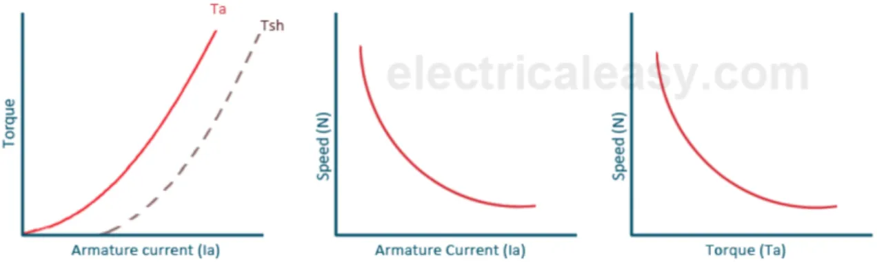
Figure 2-5: DC Series Excited Motor’s a) Armature Current Vs Torque, b) Armature Current Vs Speed, c) Torque Vs Speed graphs. ... 12
Figure 2-6: DC Shunt Motor (Self Excited) ... 12
Figure 2-7: DC Shunt Motor (Separately Excited) ... 12
Figure 2-8: DC Shunt Motor’s a) Armature Current Vs Torque, b) Armature Current Vs Speed, c) Torque Vs Speed graphs. ... 13
Figure 2-9: DC Permanent Magnet Motor ... 13
Figure 2-10 : Working as a Motor ... 16
Figure 2-11: Working as a Generator ... 17
Figure 2-12: Surplus regenerative energy utilized by cooperation of two trains (the train above is accelerating, the train below is braking) ... 18
Figure 2-13: Two train model elaborating the use of regenerative braking ... 18
Figure 2-14: Electric Train with on board storage unit ... 19
Figure 2-15: Schematic of Storage unit equipment and connections. ... 19
Figure 2-16: Storage Unit Placement at Traction Substations ... 20
Figure 3-1: Power Measurement and Control ... 21
Figure 3-2:Energy profile of a train with wayside energy storage system ... 23
Figure 4-1: Classification of Energy Storage System ... 26
Figure 4-2: A Spinning Flywheel ... 27
Figure 4-3: Urenco Flywheel ... 28
Figure 4-4: Structure and Components of a Flywheel ... 28
Figure 4-5: SMES Super Conducting Coil ... 30
Figure 4-6: Cryogenic System for Cooling of Superconductors ... 30
Figure 4-7: Capacitor ... 32
Figure 4-8: Super/ Ultra Capacitor, Double plate capacitor ... 33
v
Figure 4-10: Types of Super Capacitors ... 35
Figure 4-11: Datasheet end of life for 2.7V & 2.5V test voltage ... 37
Figure 5-1: Working Principle of bidirectional converter ... 39
Figure 5-2: Step Down Buck Converter ... 40
Figure 5-3: Gate Control Waveforms for a Buck Converter ... 42
Figure 5-4: Step up Boost Converter ... 42
Figure 5-5: Gate Control Waveforms for a Boost Converter ... 43
Figure 5-6: Buck-Boost Converter ... 43
Figure 5-7: DC/DC Bidirectional Converter ... 44
Figure 5-8: a) Buck Operation, b) Boost Operation ... 45
Figure 5-9: Half bridge 2 Quadrant Converter ... 45
Figure 5-10: Current Waveforms for Half bridge 2 Quadrant Converter ... 45
Figure 5-11: Cascaded Buck DC/DC Bidirectional Converter ... 47
Figure 5-12: Cascaded Boost DC/DC Bidirectional Converter ... 48
Figure 5-13: Modular Multilevel DC/DC Bi directional Converter ... 49
Figure 6-1: System Overview ... 52
Figure 6-2: Complete System Model ... 56
Figure 6-3: 3 Phase 132kV Industrial Supply Model ... 57
Figure 6-4: 24 Pulses Transformer ... 58
Figure 6-5: 3 Level NPC Converter ... 59
Figure 6-6: Supercapacitor Model ... 59
Figure 6-7: 2 Quadrant DC/DC Bidirectional Converter ... 60
Figure 6-8: Duty Cycle to PWM Generator ... 61
Figure 6-9: Train Modelled as a Current Source with Signal Builder ... 61
Figure 6-10: a) Train in braking state b) Train in cruising state c) Train in Braking, coasting and accelerating state ... 62
Figure 6-11: Charging Circuit of Supercapacitor with Voltage and inner current control loop ... 63
Figure 6-12: Supercapacitor Charging Response with an Ideal Voltage Source ... 65
Figure 6-13: Supercapacitor Charging Response with an overdamped system ... 66
Figure 6-14: Charging Circuit of Supercapacitor with Voltage and inner current control loop and train modelled as current source ... 66
vi
Figure 6-15: Supercapacitor Charging Response with a train modelled as current source .... 67
Figure 6-16: Charging Circuit of Supercapacitor with Voltage and inner current control loop ... 67
Figure 6-17: Supercapacitor Charging Response with train as a passive load ... 68
Figure 6-18: Supercapacitor Charging Response with a train modelled as current source .... 68
Figure 6-19: Train Profile ... 70
Figure 6-20: Supercapacitor Bidirectional power flow with a train modelled as current source ... 71
Figure 7-1 Regenerative Energy Storage Circuit Diagram ... 75
Figure 7-2: Optimal designing trade off, Energy Storage Cost per Cycle Vs Number of Cycles ... 77
Figure 7-3: Cycles per year and life of supercapacitors ... 78
Figure 7-4: Optimal Designing and Cost trade off ... 79
vii
List of Tables
Table 6-1: Systems Parameters for Modelling ... 55
Table 6-2: Control of the SC's State ... 69
Table 6-3: Simulation Setup Parameters ... 72
Table 6-4: Train Profile Under Evaluation ... 72
Table 6-5: SC's parameters for the train profile under evaluation ... 73
Table 7-1: Parameters for the application under consideration ... 79
1
1. Introduction
1.1. Background of the thesis
Trains are a major source of transportation for the urban commuters and the recent increase in their numbers made the world think of new high-speed trains and forced them to think of more planning, financing and building of new corridors along with more search on energy efficient systems [1]. No doubt that the new high-speed trains are more efficient and are getting better every day, but the focus of this thesis is on already installed railway lines who have to be made competitive with these new trains.
This thesis focuses on a 3kV DC E414 frecciabianca of Italy’s railway electric locomotives, a 4,400-kW electric traction engine which needs to be made more competitive economically to the new lines installed around the world.
Regenerative braking energy is under consideration for past decade for its use in electric vehicles and now, railway industry is considering this technology for their old and new locomotives as it allows the train to utilize the energy extracted from the braking of the train. An electric reversible grid station is also under a lot of discussion to send this extracted energy back to the grid, so it could be used elsewhere [2]. Other than that, a smart management system is implemented for controlling the traffic of the trains such that the timing of an accelerating and braking train in nearby region is synched to utilize the extracted energy from braking to accelerate the train in parallel to traction substation supply. This immediate exchange of energy between trains is the most efficient way to utilize regenerative energy, and only if this condition is not available the energy storage system comes into consideration. [3] [4]
Global warming is a reality and all the research in this sector is to shed the CO2 emission.
Regenerative braking in trains leads to substantial reduction in CO2 emission, about 8 – 17%
in commuter trains/ metros and nearly 30% in sub urban trains. Similarly, freight trains also reduce the CO2 emission, relatively less than others i.e., 5%. When regenerative braking is
employed, the current in the electric motors is reversed, slowing down the train. Regenerative energy is mature enough to store it and then utilize it directly or can also be fed
2
back into the grid resulting in less energy to be generated at the generation end which is mostly causing the emission of CO2. [5]
Initial capital cost to implement this infrastructure development is a matter of worry and this should be studied further to calculate the return of investment. This thesis will discuss about the optimised design, as well as its cost calculation and also about the return of investment for it is a commercial matter and businessmen thinks more about the returns than the cause of its use.
A model of the energy storage system along with active traction grid is proposed in this thesis. It is important to discuss an active grid which in near future will be important part of national grid and so our designing should consider such system. A train model will also be discussed in this matter and different cases will be studied with the help of this model [6].
1.2. Purpose of the Thesis
Italian railway network is analysed in detail in this thesis in continuation of the work done by [2]. 3 &'() sub urban trains are analysed and modelled in particular to increase its efficiency and an energy storage system is formed with the help of a DC-DC bidirectional converter as sending the regenerative energy back to the traction grid station requires certain coordination with the utility provider which has many constraints which are of commercial nature. Certainly, many devices are available for energy storage of such profile, some are discussed along with some of their technical parameters making it easy for the investor to choose as per their demand. A focus on DC-DC bi directional converters and, in particular, to multilevel modular converters using the cascading phenomena is done with the aim of explaining why these devices are the principal candidates for this realization. Analysis of above-mentioned preliminary designs will be applied on an existing 3kV DC railway electric substation located in Italy, which will allow us to calculate the total energy stored and their commercial prospects will also be discussed in the later part of the thesis.
Matlab simulations will be provided with the case studies in this respect and a comparison will be done with present installed system. Cost analysis and its return of investment will also be presented, making it a complete model for the use in real life for calculating almost all the parameters to realize such a system on 3 kV DC railway line and can also be extended to other systems as well.
3
1.3. Outline of the Thesis
This thesis is divided into eight chapters, first being the background and purpose of thesis explains the importance of use of regenerative energy in railway system. Then different traction technologies in use and under research are elaborated in chapter two. It also includes the principle of braking in trains along with multipurpose electric motors used in railway traction and braking. Different parameters are discussed to explain the different cases of braking which can be stored.
There are some requirements to satisfy/ consider before designing a regenerative energy storage system for railway systems, chapter three discuss some of that requirements for further analysis of the system.
There are many storage devices available in market, many parameters are to be satisfied to choose any. Shortlisting some storage devices, chapter four discusses in detail about the flywheel and supercapacitors along with the age of supercapacitor as it will be an important factor in designing of the system and also in calculating the time for return of investment. DC-DC Bidirectional converter is essential for our application, some basic converters are discussed along with the converters used for our application will be mentioned in fifth chapter.
Chapter six will elaborate the modelling of our application on Matlab Simulink, gradual building of the model from small components will be explained with results to for a full model with an active traction grid station and a storage unit of supercapacitors.
At the end of this thesis we will discuss some parameters to calculate the cost of our application. Cost is subjected to the market value of supercapacitors, for analysis purpose this chapter will discuss the replacement life of our energy storage unit along with equations for calculating the time for the return of investment.
4
2. Railway Traction and Braking Technology
This chapter will discuss about different traction systems and its components used over the time. Different parameters for choosing specific equipment will also be discussed in this chapter.
2.1. Traction Systems Over the Time
Traction systems have rich history for industrial as well as public use. The first tram was invented in England in 1602 by Mr. Beaumont, Newcastle for the transportation of coal and ore from its mine to Tyne river. This first on rails Tram was pulled by horses and this system was called Tramway. During the following centuries the transport of a cart on rails was moved from mines to transportation of peoples due the reason of comfort and reliability of rail tracks. The first horse-drawn tram in Italy made their debut in Turin in 1872 and Rome in 1877, but there were problems related to animal traction. The horses could work only for a few hours, causing great logistical problems for their care and feeding. Around 1870 they tried to remedy the problem by establishing lines with steam tram, but the problem remains and getting bigger than the benefits (smoke, sparks, ashes, big and heavy locomotives, not adapted to the environment in urban areas). To cope with they need system that resolve these issues. In Europe, electric traction started in 1879 when the first electric railway was presented at the Berlin Trade Fair by Werner von Siemens. The small "locomotive" had a power of 2.2 kW and it was supplied at 150 V between the two rails. [7]
The first line of the European Union, after some short tests in Edinburgh and Bremen was the Italian Firenze-Fiesole which was 7.10 km long. It was opened on September 19, 1890. It employed the "Sprague" system with an overhead line at 500-600 V.
At the beginning of the last century only steam locomotives dominated the railway. However, because of the smoke, which sometimes caused tragic incidents, there was more and more interest towards the electric traction. To supply the electric train, different system was used in the past, each of which are explained in the following.
The three-phase system for railway electric lines had significant developments especially in Italy. Such a system had its first application in 1902 with the electrification voltage of at 3000 V and frequency 15.6 Hz that is extended in 1913 with the unification of the voltage 3400 V and frequency 16Hz. In this case, it was able to solve problems that allowed the execution of
5
a regular electric trains with a weight of 500 tons (2 locomotives) at the maximum speed of 50 km/h.
In 1927, the Rome –Sulmona line was chosen to test new 10 kV-45Hz electrification standard characterized by high slopes and 172 km long. Perhaps even the overhead line and even tests were carried out (but not documented). After more than half a century of working, on May 1976 the last train pulled by two locomotives three-phase type E431 and E432 between Alessandria and Acqui. After the necessary plant modifications, the train restart from Acqui to Alessandria this time pulled by a DC electric locomotive E 656 026, (4200kW, speed. Max 160 km / h) of the latest generation.
After the first experiments started in 1927 and carried out with the first 14 locomotives prototype groups E.625/626 and decide either to electrify the railway lines with the new DC 3000 V system or continue with the proven three-phase system which its pros and cons were known for more than two decades. The DC system was revealed itself a system with excellent performance even on lines with steep slope, critical lines in the Southern Italy chosen to evaluate limits and merits of the new system. The German-speaking countries preferred to experiment an AC single-phase traction system supplied at 15 kV and 16.7 Hz, to increase the line voltage and at the same time to use the commutator brushed motor instead of DC traction motors. In the early 50s of last century the French railway company experimented the 25 kV and 50 Hz system, which required the construction of multisystem locomotives with 1500 VDC and 25 kV 50 Hz systems. The 12 kV 25 Hz system was developed in United States in the last century.
Nowadays, some of the previously mentioned system are used, each of which are operating in several or just one country. Japan, France and Netherlands are using 1500 VDC systems, Italy, Russia, Poland, Spain are using 3000 VDC systems. Still some of the countries are using AC systems e.g. Germany, Austria, Sweden and Switzerland used 15 kV 16.7 Hz and France, Spain (HS), Italy (HS), Japan 25 kV 50 Hz systems. The USA using three standards for electrification of trains 25 kV 60 Hz, 12 kV 25 Hz and 12.5 kV 60 Hz.
2.2. Types of Railways Traction Systems
The evolution of electric motors for railways and the development of electrification from the middle of the 20th century meant that this kind of motor was suitable for railways. Types of railway traction systems can be divided on the bases of their energy source.
6
Figure 2-1: Types of Railway Traction systems in use
High infrastructure cost required to carry electrical energy to the moving train which requires constructing long electrical supply catenary lines. Pantographs enables the motor to be connected to the catenary during traction. Graphite block is used for the contact between pantograph and the catenary line which works as lubricant which conducts electricity. Graphite is brittle in nature so a bad pantograph or a bad wire can damage the overall structure causing arching and heating of graphite and catenary lines. Much has been developed to minimize such issues which is not in the scope of this thesis.
A lot of research is done for increasing the efficiency of engines in past century to minimize the ROI in railway systems. Evolutions in the electric traction motors and dynamic brakes made it possible to store braking energy and utilized it to make most of wasted energy. Electric traction motors are used now a days in traction system and the motors used for this purpose can also be used for slowing down or stopping the train altogether without using the lowlife braking pads. The kinetic energy of the moving train is converted into electric energy which can be used at the same time to power up an accelerating train in nearby region or can be stored to be utilized afterwards. Other than that electrical traction can be said to be clean, respectful of the environment and efficient.
Types of Railway Traction
Steam Diesel Mechanical Transmission Hydraulic Transmission Electrical Transmission Electric DC Motor In-series excitation In-parallel excitation Independant excitation AC Motor Mono phase (Collector) Three phase Synchronus Three phase Asynchronus
7
2.3. Train movement and performance calculation
Train movement can be defined by some key variables as its velocity, acceleration and position during its single motion and Newton’s second law describes them through kinematic equations. [8]
For instance, we can start with the train motion on an inclined rail surface which can be expressed mathematically by using free body diagram showing all the forces acting on it.
*+− *. = 0122# *. = *.. + *4567 + *8.74
where *+ is the tractive effort of the train, *. is the resistance force of the train, *.. is the rolling resistance force of the train, *4567 is the aerodynamic drag force of the train, *8.74 is the gradient force of the train, 0122 is the total effective mass of the train, and # is the train acceleration.
Rolling resistance force *.. is the resistance to motion of rotating parts such as frictional torques (bearing torques, gear teeth friction, brake pads). Rolling resistance can be expressed mathematically as:
*..= 9: ; ≈ (9> + 9?@);
where ; is the axle load, 9: is the rolling resistance coefficient, 9> and 9? are two arbitrary constants, and velocity of train is represented by @.
Aerodynamic drag resistance force *4567 is the force exerted by air on the train which influences the motion of the train. The aerodynamic resistance force results from three basic effects:
1. Pressure difference in front and behind of the train due to the separation of the air flow and causing the vortex creation behind the vehicle.
8
2. Surface roughness of the vehicle body also causes a skin friction and it may alter over time due to the paint or lamination deterioration on the train body.
3. Internal flow of air entering the train by small openings or air gaps in its outer body.
It is common to express the aerodynamic drag force in the basic form as:
*
4.78 B ?CDEFGHIJKLEFGM
where N7O. is air density in (kg/PQ), R4 is an aerodynamic drag coefficient, ST is the projected frontal area of the train, and @7O.C is the speed of air relative to the train body.
The gradient force *8.74 if on a slope will act in the opposite direction of the train for uphill and in the direction of the downhill assigning the negative and positive signs respectively. The gradient force is a constant force as long as the slope is constant and can be expressed mathematically as:
*8.74 = ±0122g sinV
where g is the gravitational constant (9.81 m/WC ) and V is the slope angle.
The train’s aerodynamic and rolling resistance forces can only vary with the train speed and can be separated from the gradient force for convenient use.
Total drag force is a combination of these two forces. Many equations are defined to express the drag resistance force. The quadratic form of Davis equation is commonly used as:
*4.78 B XYZLY[LM
where \, ], and ^ are drag force coefficients. These coefficients have different values for open air and tunnel conditions.
Similarly, the train movement can be modelled mathematically for different modes, such as powering mode i.e., acceleration of the train to maximum speed and the switched to power saving mode or constant speed mode and then the braking mode when the train is deaccelerated. It is important to mention that before the braking mode trains always runs in coasting mode which is a phenomenon in which power is removed and the train deaccelerate
9
naturally. Newton’s second law of motion can be used to calculate the tractive effort taking in consideration the impact of all the previously mentioned forces.
2.4. Braking energy
Braking energy can be divided in two cases where energy recovery is possible, the first one involves potential energy given by a constant braking along a downhill, in which the power peaks are low, but the braking time is of some minutes, this is called “energy intensive”. The second is the kinetic energy given by a full braking to a zero speed i.e., a complete stop along a flat line, in which high power peaks are involved but the time is in few seconds, this is called” power intensive”. [6]
2.4.1. Energy intensive
A train moves downhill at constant speed and the potential energy is turned into braking energy. Considering a global coefficient of efficiency as _`, potential energy ;` is given by;
;` = _`Pa(ℎ?− ℎC)
with P as the mass of the train, a the gravitational acceleration and (ℎ?− ℎC) the altitude drops. If the braking time is c`, the average potential power as d` is;
d` = ;` /c`
2.4.2. Power intensive
A train moving on a flat track starts to decelerate constantly from high speed to a complete stop. The Kinetic energy of the moving train is turned into braking energy and considering a global coefficient efficiency _e, kinetic energy ;e is given by;
10
with P as the mass of the train, (@?− @C) is the drop-in speed of the train. If the braking time is ce, then the average kinetic power de is given by;
de = ;ece
Detail analysis of the track shows that this braking power is in the range of MW and is worth saving for better efficiency of the system.
2.5. Traction Motors
An electric motor used for the propulsion of locomotives is called a traction motor. Traction motors convert electrical energy into traction energy by moving the vehicles wheel as per the desired speed. They have many advantages over IC engines and steam engines for their speed control friendliness towards the nature. Traction motors are also being used in hybrid vehicles such as diesel-electric and battery electric vehicles. In all cases the working phenomenon of the motor is same, electric energy is converted into mechanical energy through rotator which could be either rotational or a linear movement as per the desired requirements.
DC motors are the oldest type of traction motors for they provide high torque at lower speeds giving a much more superior speed/torque characteristics then of an AC motor. Although with all the research and high-speed trains approaching to a higher target every day, AC motors are preferred over DC motors as their speed control is easier and the also the infrastructure cost of converting 3 phase AC to DC is saved. Power semiconductors have made it possible to install variable frequency drives on the trains which allows a wide range of speed and also uses induction motors without wearing parts like brushes and commutators as used in DC motors. This thesis covers only the 3KV DC rail line, so we will discuss some DC traction motors briefly in the next section.
2.5.1. DC Motors
Operation of the DC motor is based on the principle that when a current carrying conductor is placed in a magnetic field, the conductor will feel a mechanical force whose direction can
11
be given by Fleming’s left-hand rule. DC motor and DC generators have the same structure and same machine can run as a DC generator or a DC motor.
DC motors are defined by their nature of excitation/ field windings, we have following kinds of DC motors being used;
Figure 2-3: Types of DC Motors
In DC series excited motor, the field is connected in series with the armature. DC motors with series field windings are the oldest type of traction motors. It is a variable speed motor in which speed is low at high torque and high at low torque. However, at light or no-load, the motor tends to attain dangerously high speed and should not be run on no- load condition. The motor has a high starting torque. It is,
therefore, used where large starting torque is required such as in elevators and electric traction and also where the load is subjected to heavy fluctuations and the speed is automatically required to reduce at high torques and vice-versa. Following graphs show the characteristic relationships of a series excited DC motor.
DC Motors
Separately Excited Self-Excited
Shunt Excited Series Excited Compound Excited Cumulative Compound Differential
Compound
Permanent Magnet
12
Figure 2-5: DC Series Excited Motor’s a) Armature Current Vs Torque, b) Armature Current Vs Speed, c) Torque Vs Speed graphs.
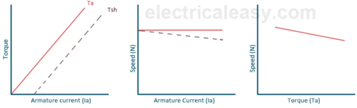
Fig.2-5 shows the connections of a DC shunt motor. The field current is constant since the field winding is directly connected to the supply voltage V which is assumed to be constant. Hence, the flux in a shunt motor is approximately constant. The flux φ and back e.m.f. Eb in a shunt motor are almost constant under normal conditions, so the speed of a shunt motor will remain constant as the armature current varies. There is slight change in the speed of a shunt motor from no-load to full load. Hence, it is essentially a constant-speed motor. The starting torque is not high as torque is directly proportional to the armature current. The field winding can be separately excited or can also be connected to the supply voltage. Separate excitation gives us more flexibility in controlling the current driving the motor.
13
Figure 2-8: DC Shunt Motor’s a) Armature Current Vs Torque, b) Armature Current Vs Speed, c) Torque Vs Speed graphs.
The permanent magnet motor uses a magnet to supply field flux. Permanent magnet DC motors have excellent starting torque capability with good speed regulation. A disadvantage of permanent magnet DC motors is they are limited to the amount of load they can drive. These motors can be found on low horsepower applications.
2.6. Electric Braking
According to our applications in real world we might need our motor to slow down or to stop completely and quickly. The motor can be stopped or slowed down to a desired speed by using either,
1. Mechanical (friction) braking 2. Electric braking.
Brake shoe or a brake pad is used in mechanical braking to stop or slow down the locomotive with the friction between the moving parts of the motor and the brake pads. Kinetic energy of the moving part is dissipated as heat. Non-smooth stop and greater stopping time are some of the disadvantages of mechanical braking including the wearing of the brake pads/ shoe and its replacement cost.
14
In electric braking, the kinetic energy of the moving parts become the prime mover of the motor and moves the armature to make a DC generator out of a DC motor which converts kinetic energy into electrical energy which is dissipated in a resistance as heat or returned to the supply source. Following three methods of electric braking are used for DC series and shunt motors:
1. Dynamic braking 2. Plugging
3. Regenerative braking
It is worth mentioning that electric braking alone cannot hold the motor to a mare stationary position and mechanical braking is necessary for it. Electric brakes reduce the wearing of mechanical brakes increasing their life and cuts down the stopping time.
2.6.1. Dynamic braking
It is also called Rheostatic braking as the armature of the running motor is disconnected from the supply and is connected across a variable resistance. The field winding is left connected to the source. The armature rotates in a strong magnetic field i.e., operates as a generator, sending a large current through resistance R. This causes the energy possessed by the rotating armature to be dissipated quickly as heat in the resistance and back EMF brings the motor to a standstill quickly.
Armature current can be written as;
f7 = !g h + h7 =
&?ij h + h7
Where, !g ∝ ij , !g being the back emf, h7 being the armature resistance and h the external resistor for energy dissipation.
15 cg = &Cf7j = &Cj l
&?ij
h + h7m = &QijC
Where &C and &Q are constants.
2.6.2. Plugging
Connections to the armature are reversed in this so that motor tends to rotate in the opposite direction which intern provides the necessary braking effect. We should be careful with such method to cut off the supply when motor comes to rest, otherwise the motor will start rotating in the opposite direction. Only armature connections are reversed while the connections of the field winding are kept the same, so that only the current in the armature reverses and back electromotive force remains in the same direction.
Armature current can be written as;
f7 = ' + !g h + h7 = ' h + h7+ &?ij h + h7
And braking torque can be written as;
cg= &Cf7j = &Cj l ' h + h7+
&?ij
h + h7m = &Qj + &nijC
2.6.3. Regenerative braking
It is quite similar to dynamic braking, the difference being instead of a variable resistor, it is utilized by a parallel load or is saved in storage device. It can be divided in two cases, one where back EMF is less than the applied voltage V, and the other being the case when back EMF increases then the applied voltage. For the first case, excitation current can be increased to an extend to reverse the direction of the current and in the second case when speed of the locomotive increases from the no load condition i.e., downhill free movement. Back EMF increases from the nominal value keeping the excitation current constant which causes the torque to reverse until back EMF is less than the applied voltage. Series DC motors are also
16
converted to work as a shunt motor since the resistance of the field winding is low and a series resistance is connected in the field circuit to limit the current value within the safe region.
In comparison to the traditional braking, regenerative braking has many advantages, such as [9]:
1. Better controlled braking.
2. Better efficiency and effective in stopping and slowing down the vehicle. 3. Prevents wear on mechanical brake systems.
4. Better fuel economy.
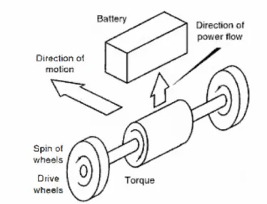
The working principle elaborates that regenerative braking is actually a braking method that utilizes the mechanical energy from the motor. It converts kinetic energy into electrical energy and fed back it into the battery source.
Figure 2-10 : Working as a Motor
Train uses the motor to slow down when brakes are applied, and then the electric motor starts to work as a generator and recharge the batteries.
17
Figure 2-11: Working as a Generator
The braking controller is the heart of the system in regenerative braking because it controls the overall process of the motor. All the parameters of the brake controller are monitor; the speed of the wheel, torque, rotational force and generated electricity. The generated energy is fed to the batteries for future use. The brake controller directs the regenerative energy into the batteries or capacitors and checks for the state of charge to stop charging if the batteries or the super capacitors are fully charged.
2.7. Regenerative braking in Railway System
Regenerative braking essential is now a days for the better efficiency of the railway system. To maximize the usage of the regenerative energy many methods are introduced, and some are under investigation. It includes timetable optimization, train speed profile adjustment and storing it in flywheel or a super capacitor for future use. Many numerical methods and algorithms are designed to calculate average energy saving for using these methods.
Most efficient and effective way to utilize regenerative energy is to distribute it to the neighbouring trains [10]. Optimized models are formulated using the train speed and time of stopping and accelerating to form a multi train cooperation,
18
Figure 2-12: Surplus regenerative energy utilized by cooperation of two trains (the train above is accelerating, the train below is braking)
To understand it in a better way, one can consider the following diagram stating two trains operation in parallel, one braking and the other absorbing that energy,
Figure 2-13: Two train model elaborating the use of regenerative braking
The surplus regenerative energy, which could not be transferred to any nearby train can also be stored in a storage unit which could be any of the fast energy storing devices as braking time ranges from 6s to 15s in case of stopping the train while it can be in minutes for downhill condition.
Placement of energy storage unit is an important factor for designing of such units, they can be placed on board or can be placed at the nearest substation. A trade of has to be consider
19
for such choices, but both of these are already in consideration as the on-board storage unit can suffice the onboard energy demand for lighting, heating or auxiliary supplies on train. [11]
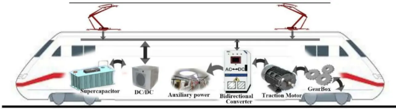
Figure 2-14: Electric Train with on board storage unit
The different components used in energy storage systems are also designed specifically as per the placement of storage unit, such as for places where the distance between the two-traction substation is far enough to drop the catenary voltage, the unit should be maintenance free. Other than that, the placement of storage unit at already present substations is promising for the fact that it has almost the perfect placement for such equipment.
Figure 2-15: Schematic of Storage unit equipment and connections.
The components depend on the system we are working on, now a days AC traction is used in high speed trains, our focus in this thesis will be on a 3kV DC system. It requires a DC/DC
20
converter to charge the supercapacitor placed at the nearest substation. It also requires a DC/DC converter to supply it back to the catenary for the accelerating train or and DC/AC converter for the energy use at the station where all the equipment is AC.
Figure 2-16: Storage Unit Placement at Traction Substations
Wayside energy storage units are placed between two substations and are of specific use at places such as a tunnel or some other restricted are for substation building. It is also used for keeping the catenary voltage to a balance for better efficiency of the system.
21
3. Requirements for Regenerative Braking Energy
Storage in Railway Systems
Energy storage systems are now in use and under investigation for rural and urban transportation system using regenerative energy to seek energy efficiency while satisfying high-power density and high return on investment.
Flywheels, supercapacitors and batteries are already in use in electric vehicles at low voltages, this thesis discusses some of these options for high voltage up to 3kV for a railway system in Italy.
We will elaborate lifetime, cyclability, cost, energy characteristics, ease of installation and environment effects, such as temperature for different energy storage options in this chapter.
Figure 3-1: Power Measurement and Control
3.1. Rail requirements for storage system
At the time of braking, if there is no rail vehicle in nearby area, the energy given back by this train will cause an increase of the catenary voltage. This level of voltage will cause that the converter to input the current to the storage device. Once the catenary voltage will give back to its nominal value, or in case of reaching its maximum capacity of storage, the converter will decrease current up to zero and the energy will remain stored. The stored energy can be used
22
in many ways, also the accelerating trains can use this energy along with the energy from traction substation. So, there are many things to consider for designing a storage system.
3.1.1. Headway and duration of operation
Operating conditions continuously changes as track headways can be as low as 2 minutes during rush hour and 20 minutes or longer during off-peak hours. Trains accelerate for 15 - 60 seconds and may brake to a stop in as little as 15 seconds. Typical operating headways are 3 minutes during peak hours and 5 to 15 minutes in semi-peak and off-peak hours, with an average headway of about 5 minutes. Rail authorities are decreasing headway to accommodate more passengers into the existing rail infrastructure and more rail authorities are working toward 2.5-minute headway.
The energy storage sizing must consider the headway, the expected life of the system and return on investment (ROI). An undersized storage will have poor performance and decreased life. An oversized storage will have a longer ROI.
3.1.2. Voltage, Power and Energy Capacity
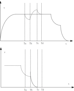
The goal of an energy storage system is to capture and supply the captured energy to trains in a cost-effective manner. Storage system power and energy sizing are key considerations for optimized performance and ROI. Figure 5 shows the energy profile of a typical metro train with a WESS installation from Bombardier. At 0 to 30 seconds a train is accelerating and a WESS is discharging. At 30 to 50 seconds the train is maintaining its speed. At 50 to 70 seconds the train is regen braking and the storage system is charging.
23
Figure 3-2:Energy profile of a train with wayside energy storage system
Train braking events are typically short, 20 seconds in this example. Most braking energy that storage system can capture is available during the first 15 to 18 seconds of the braking event. For this example, the red box shows ideal WESS sizing, 500 kW at 15 to 18 seconds. The red dotted line shows the third rail voltage and how much the voltage changes when a train accelerates and decelerates.
Every storage system installation size may differ and should be evaluated on a case-by-case basis. In our case, our catenary voltage is 3kV. The range for storage system designing will be defined in the next sections.
3.1.3. Controls, Energy Management and Diagnostics
Most efficient way of utilizing regenerated energy is when it is transferred to a train which is accelerating in the nearby region. The energy storage measurement and control system must acquire run time data to promote the use of regenerative braking energy directly to other accelerating trains.
24
Storage units must not be charged by consuming power from the traction substation. In addition, it should discharge to a Load Train as soon as possible to minimize leakage losses.
3.1.4. Location, Ambient Conditions and Auxiliaries
Energy storage units can be typically installed in an existing traction substation and integrated with existing traction power equipment or can be installed in a new or existing structure near a passenger station. Existing substations typically have limited space for new equipment or may be underground so modular type of systems are designed to fit into the existing space. Design must consider the operating environment where it will be installed as substations are typically dusty and can infiltrate electrical equipment shortening their operational life. The energy storage substations should be designed for indefinite operation between temperature ranges specified in EN 50155-2 Railway applications.
3.1.5. Reliability and Maintenance
Principle mission of transit operators is to provide uninterruptable and reliable transportation to its commuters. Energy storage gives an option to provide this facility with cost saving option, but we do not need it to interrupt the railway system only to overcome some issue in the energy storage system. The energy storage system must be reliable enough, so it does not interfere with daily rail operations, rail reliability or safety. Transit operators may not compromise on their mission and can also shut down the energy storage option completely if it interrupts or delays the operation of railway.
Keeping all that in consideration, energy storage system must be reliable and require little maintenance and should be easily assessable to the engineer for maintenance. Transit operators can shut it down if the maintenance time and cost are higher than their thinking and all the investment will be of no use.
25
3.1.6. Return on Investment (ROI)
Return on investment varies case by case and it is a choice of transit operators. Normally, 5 to 8 years is what they ask for from reliable and already tested equipment. ROI is a highly volatile topic for brief discussion, it will be explained in the next parts of the thesis. Our system returns primarily from reducing total energy consumption and reducing peak power demand. Every utility has different rates for energy usage and peak power demand.
26
4. Energy Storage Devices
The storage technologies which enabled us to implement it for cost effectiveness is still the most expensive part in our system, even though it varies widely for different technologies of which we will discuss some in this section. It is determined by the capital investment, maintenance cost, efficiency, lifespan and replacement cost of the energy storage system. The commonly used energy storage technologies for regenerative energy storage are:
Figure 4-1: Classification of Energy Storage System
4.1. Flywheels As Mechanical Energy Storage Devices
A flywheel is a mechanical device which is specifically designed to store rotational energy, then released to the intended application as per the requirements. They resist the changes in their rotation and very less energy is dissipated over time. The working principle of this unit is relatively simple, catenary voltage increases when brakes are applied and if no train is available to utilize it then a flywheel uses it to accelerate by increasing its input current. As the catenary voltage drops or flywheel reaches its maximum speed, it cuts off from the system and the kinetic energy remains safe in the flywheel until the catenary voltage drops, that is when a train accelerates, and the fly wheel will provide the extra energy in parallel to the traction energy.
27
Figure 4-2: A Spinning Flywheel
Two popular geometry of flywheels: the uniform cross-section wheels and the thick-rim flywheels. The kinetic energy that can be stored in a flywheel spinning at an angular velocity ω can be computed by the following expression:
o! = 1 2frC
Where, f is the moment of inertia of the wheel. If the thickness is given, moment of inertial can be found as:
f = 1 20hC
Where, 0 is the mass and h is the radius of the wheel. Angular velocity of the wheel is maintained by applying torque, that is:
s = f\
28
Many types of flywheels are used in many applications now a days, but there is one which this thesis feels to mention made by Urenco Power Technologies, UK. UPT’s unique world leading high-speed flywheel’ energy storage technology, to real-time power management and voltage support for the traction industry. It relies on technology developed over more than 30 years for high speed gas centrifuge and has itself undergone several further years of
development. It is one of the most advanced commercially available flywheel energy storage system. Zero maintenance, 20-year life and high cyclic capability make it ideally suited to applications in rail power supplies.
4.1.1. Structure and Components of a Flywheel Storage System
A typical flywheel consists of a spinning rotor, magnate, bearings, a power electronics interface, and a housing. A flywheel system suitable for energy storage is schematically shown in Figure,
Figure 4-4: Structure and Components of a Flywheel
A composite cylinder with high mass is wound as a combination of carbon / glass / carbon fibre in one continuous operation. The centre bore of the cylinder is loaded with permanent magnet powder (Neodymium Iron Boron -NdFeB) which is wound into the composite to provide the magnetic medium. The magnetic inner core is magnetised with two different
29
patterns. Poles are imprinted circumferentially to form one half of a passive magnetic bearing at one end and the rest of the rotor is magnetised axially with twelve poles which form the rotor of a permanent magnet machine. A corresponding 3-phase stator completes the motor / generator design. This is adopted from high-speed centrifuges in the nuclear industry which requires no maintenance and operation in high vacuum is made sure to minimize the drag loses.
Flywheel systems are already in test use in London and New York metro’s and they provide a very fast response to changes in power demand and is able to switch between full power motoring and generating modes within few milliseconds. It can work for millions of cycles without degradation in performance and modular system may be expanded as required. Flywheel energy storage system requires minimal maintenance and have a life ranging to 20 years.
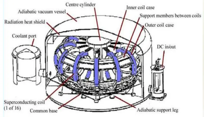
4.2. Superconducting Magnets SMES
A Superconducting Magnetic Energy Storage system stores the energy as magnetic energy in a superconducting magnet which is cryogenically cooled for achieving a system with negligible losses. [12]
Superconductivity is a phenomenon of exactly zero electrical resistance and expulsion of magnetic fields occurring in certain materials when cooled below a characteristic critical temperature. It is characterized by the Meissner effect. SMES stores energy in the form of dc electricity by passing current through the superconductor and stores the energy in the form of a dc magnetic field. The conductor for carrying the current operates at cryogenic temperatures where it becomes superconductor and thus has virtually no resistive losses as it produces the magnetic field.
4.2.1. Components of SMES System
It needs a superconducting coil with magnate, it is cooled by a cryogenic system. As for other devices, it also needs a power converting devices for bi directional flow of power.
30
Figure 4-5: SMES Super Conducting Coil
The superconducting SMES coil must be maintained at a temperature sufficiently low to maintain a superconducting state in the wires. The temperature ranges at about 4.5K. Helium or liquid nitrogen are used as a coolant for reaching and maintaining this temperature.
31
Current will always continue to flow in a supercapacitor even after the voltage across it is removed, the fact that the superconductor has nearly zero resistance elaborates such statement.
The stored energy is inductive in nature and can be given as,
! = 12 t fC
SMES systems have the ability of fast response within seconds, they can find its application in railway industry, but more research is required to implement it on such a scale.
4.3. SUPER CAPACITORS
A double layer capacitor which stores energy by charge transfer at the boundary between electrode and electrolyte. Two electrodes, a separator and an electrolyte are used in the construction of a super capacitor. Activated carbon are used to make the electrodes in which particles are strongly packed, which provides a high surface area responsible for energy density acting as polarizable electrodes. The membrane which divides two electrodes also allows the mobility of charged ions and forbids electronic contact. The amount of stored energy is a function of electrodes surface area, the size of the ions, and the level of the electrolyte decomposition voltage. Super capacitors have high power density and relatively low energy density and a very small charging and discharging time which makes it feasible for our application of regenerative energy storage.
4.3.1. Overview of Capacitors
To understand the more about super capacitors we need to understand about the capacitors. Super capacitors use the same principle as of capacitors.
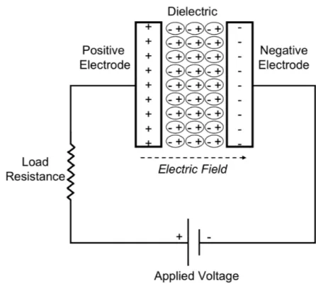
Conventional capacitors consist of two conducting electrodes separated by an insulating dielectric material. When a voltage is applied to a capacitor, opposite charges accumulate on the surfaces of each electrode. The charges are kept separate by the dielectric, thus producing an electric field that allows the capacitor to store energy.
32
Ratio of charge stored to the applied voltage is defined as the capacitance of a capacitor,
R =u '
Where R is the capacitance in Farad * and defined for a 1 farad capacitor which stores 1 coulomb of charge u when a potential difference of 1 volt ' is applied between the plates.
Figure 4-7: Capacitor
Capacitance is directly proportional to the surface area of the electrodes and inversely proportional to the distance between them,
R = vwv.S x
Where, εz dielectric constant (or “permittivity”) of free space and v. is the dielectric constant of the insulating material between the electrodes. S is the surface area of the electrodes and x is the distance between them.
33 ! = 1
2R'C
Equation for the power is dependent on the equivalent series resistance of the capacitors,
d{7| = 'C 4h
h is the equivalent series resistance.
Capacitors have high power densities but low energy densities, they can store less total energy then the electrochemical batteries but can deliver this energy at a faster rate.
4.3.2. Super Capacitors
Supercapacitors work on the same basic principles as conventional capacitors. However, they are made of electrodes with much higher surface areas and much thinner dielectrics that decrease the distance between the electrodes. This means that super capacitors have much higher capacitance and energy than a conventional capacitor.
34
A Ragone plot is shown for the performance comparison of various energy-storing devices is the specific power in W/kg plotted versus the Specific energy in Wh/kg on a logarithmic scale to show the comparison of very different devices.
Figure 4-9: Regone Plot Power Density Vs Energy Density
The plot clearly shows that power density of capacitors and supercapacitors is far more than the batteries or any other electrochemical fuel cells and it is requirement of our application to have the charging and discharging time of our storage device to be less, within seconds a train decelerate to a stop and in few seconds, it accelerate to a speed where traction curve tends to its normal region. Super capacitors have higher energy density than conventional capacitors and can store more energy per unit area.
Different kinds of supercapacitors are in use and some are under development, follow flow table shows some kinds of supercapacitors,
35
Figure 4-10: Types of Super Capacitors
4.4. Age and Life time Estimation of Supercapacitors
The lifetime and reliability of storage devices are important factors to determine the feasibility of the application it is used for. Like all capacitors, Super capacitors are restricted by the level of discharge allowed to maintain life, and they have an internal resistance that can limit their power transfer. A capacitor is considered to have reached the end-of-life if the capacitance drops to 80% of the initial value, or if the internal resistance doubles from the initial value. Many models and algorithms are formed to find the factors which cause the aging of super capacitors.
Life of a supercapacitors is much more than the other charge storage devices as there is no transfer of charge between electrolyte and electrode and there are no chemical or composition changes associated which causes permanent changes in the composition of the electrodes and the electrolytes. It is obvious to say that the lifetime of a supercapacitor depends mostly on the evaporation of the liquid electrolyte with time. This evaporation is a function of temperature, voltage applied and moisture. Other than that, current and the backup time also alters the life of a supercapacitor.
4.4.1. Expected lifetime
Many models are presented to find out the expected life time of the super capacitors. Factors involved in such models includes temperature, applied voltage, humidity, current and backup
Super Capacitors Electric Double- Layer
Capacitors Carbon Nanotubes Carbon Aerogels Activated Carbons Pseudocapacitors Conducting Polymers Metal Oxides Hybrid Capacitors Composite Hybrid Battery-Type Hybrids Asymmetric Hybrids
36
time. One such models shows a relationship between expected life, temperature, applied voltage and moisture [13].
!~ = t:cT'T0T
Where !~ is the expected lifetime, t: is the rated life time temperature factor, 'T is the voltage factor and 0T is the moisture factor.
10 degrees rule states that for every 10 degree decrease in temperature, life time of the supercapacitor is doubled. Temperature factor can be expressed as,
cT = 2+?>Ä +Å
Where c: and cJ are rated and operation temperature of the supercapacitors. Similarly, 'T is also modelled as,
'T = ': 'J
Where applied voltage lay between the cut off voltage and the rated voltage.
A more complex model is shows that there is more to it then these parameters. A test was designed for this purpose in which each supercapacitor is charged at the rated current to the rated voltage, undergoes a rest period of 5 times the time constant. The supercapacitor is then discharged at rated current to half rated voltage, and another rest period takes place before measuring the final voltage. The capacitance and ESR are evaluated according to the following equations, [14] R = f.7Ç14 $4 'ÉÇ7.Ç− '2O6OÉÑ h = '2O6OÉÑ− ' .7Ç14 2 Ö f.7Ç14
37
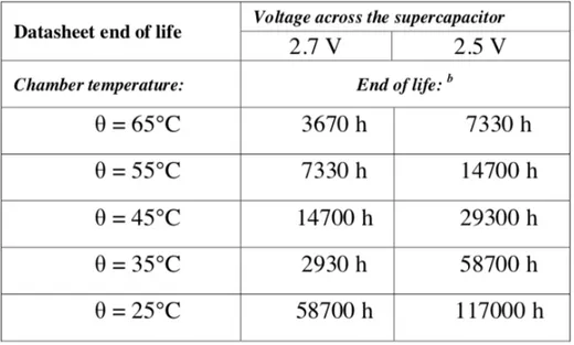
Normally capacitance will decide the end of life for a supercapacitor. Temperature has a significant effect on supercapacitor lifetime, and a typical reference is that an increase in 10°C will halve lifetime. At rated temperature of 65°C the capacitance degrades 16 times than that of at a room temperature of 25°C. Arrhenius equation which looks at the temperature dependence on the rate of a chemical reaction was applied to give following equation,
$O = ÜJ%eà+FÄáE
where cO is the absolute temperature of interest in Kelvin, $O is the reaction time in hours, &â is Boltzmann’s constant, ÜJ is a parameter to be determined, and !7 is the activation energy in electron volt. The time to end of life for the two test points is represented by $1 and $2, and the corresponding absolute temperatures are c? and cC.
Similarly, a calendar equivalent degradation tests are performed by applying constant voltages at different temperatures and electrical variations are measured. The table shows some of that results. [15]
Figure 4-11: Datasheet end of life for 2.7V & 2.5V test voltage
4.4.2. State of Charge
A fuel gauge of the electric storage device is referred to as a state of charge which tells the status of the storage unit in percentage of energy stored or available for use. It is measured
38
in directly through other parameters as voltage and capacitance in our case. It is directly proportional to the voltage and capacitance of the storage unit.
! =R 'C 2
It is an important factor for our control scheme through which our system is optimized. The application under consideration will also be analysed to present its life and replacement time in latter chapters.
39
5. DC-DC Converter
The bidirectional dc-dc converter along with energy storage has become a promising option for many power related systems, including hybrid vehicle, fuel cell vehicle, renewable energy system and so forth. This thesis will elaborate one for the 3kV railway regenerative braking system along with its model in Simulink and a case study for further strengthen the case of investing in such applications. It not only reduces the cost and improves efficiency, but also improves the performance of the system.
In the electric railway application, an auxiliary energy storage battery/ super capacitor absorbs the regenerated energy fed back by the electric machine to the DC catenary line. In addition, bidirectional dc-dc converter is also required to draw power from the auxiliary battery to boost the high-voltage bus during vehicle starting, accelerate and hill climbing. With its ability to reverse the direction of the current flow, and thereby power, the bi- directional dc-dc converters are being increasingly used to achieve power transfer between two dc power sources in either direction.
Figure 5-1: Working Principle of bidirectional converter
d? = '? f? & dC = 'C fC
If the losses are kept constant, following relation can be deducted,
1 ' ∝ f
40
To realize the double-sided power flow in bidirectional dc-dc converters, the switch cell should carry the current on both directions. It is usually implemented with a unidirectional semiconductor power switch such as power MOSFET (Metal-Oxide- Semiconductor-Field-Effect-Transistor) or IGBT (Insulated Gate Bipolar Transistor) in parallel with a diode, because the double-sided current flow power switch is not available.
5.1. Introduction to DC-DC Converter
The DC-DC converters are widely used in regulated switch mode DC power supply and motor drives. The average dc output voltage must be controlled by changing the switching time of the switch to our desired value. There are many kinds of switch mode DC converters also called as chopper, but we will only discuss some as per our model requirement.
5.1.1. Step Down Buck Converter
A step-down converter produces a lower output voltage than the dc input voltage.
Figure 5-2: Step Down Buck Converter
Assuming an ideal switch is used, and a constant input voltage is applied. The average output voltage in terms of switch duty cycle can be written as,
'w = 1
cÉ ä @w($)($ +ã