Scuola di Ingegneria Industriale e dell’Informazione Master of Science in Energy Engineering
Master Thesis
BOIL OFF GAS HANDLING ON LNG
FUELLED VESSELS WITH HIGH PRESSURE
GAS INJECTED ENGINES
Supervisors:
Prof. Paolo CHIESA Prof. Petter NEKSÅ
Candidate:
Arrigo Battistelli
Student ID number 801593
1 Introduction 3
2 Background 5
2.1 LNG as ship fuel . . . 5
2.1.1 Motivations for LNG as a ship fuel . . . 5
2.1.2 Ship propulsion alternatives . . . 7
2.1.3 LNG fuelled ships . . . 9
2.2 Tank types . . . 11
2.3 BOG handling . . . 13
2.3.1 BOG reliquefaction on LNG Carriers . . . 14
2.4 Systems for 2-Strokes Low Speed Engine Propulsion . . . 20
2.4.1 ME-GI engines . . . 21
2.4.2 High Pressure BOG compression . . . 22
2.4.3 High Pressure LNG Fuel Gas Supply Systems . . . 23
3 Heat pump process 29 3.1 Heat pump process layout (HeP) . . . 31
3.1.1 Heat pump with dedicated Tank Reflux pump layout . . . . 33
3.1.2 Heat pump with BOG fed Auxiliary engine layout (HeP-AUX) 34 3.2 Alternatives to the Heat Pump process . . . 36
3.3 Selection of a reference case. . . 38
3.3.1 Main engine . . . 39
3.3.2 Auxiliary engines . . . 40
3.3.3 Heat leak calculations . . . 41
3.4 Refrigerant . . . 43
4 Computer simulations 45 4.1 Heat Pump Model flowsheet . . . 46
4.1.1 LNG fuel tank model . . . 48
4.2 Heat pump model structure . . . 50
4.3 Inputs to the Heat Pump Model. . . 53
4.4 Inputs to other models . . . 56
4.5 Heat Pump Model Simulation Results (HeP) . . . 56
4.5.1 Normal operation scenario: HeP - 100% NCR . . . 58
4.5.2 Sensitivity Analysis on the normal operation scenario: HeP - 100% NCR . . . 63
4.5.3 Part load scenario: HeP - 50% NCR. . . 68
4.5.4 Part load scenario: HeP - 20% NCR. . . 71
4.5.5 Idle/Harbour scenario: HeP - 0% NCR - 100% AUX . . . 74
4.6 Heat Pump with BOG feed to Auxiliary engines simulation results (HeP-AUX) . . . 77
4.6.1 HeP-AUX: 100% NCR . . . 78
4.7 Evaluation of alternative process layouts . . . 80
4.7.1 Intercooled heat pump cycle . . . 80
4.7.2 BOG recirculation in the Tank Reflux system . . . 82
4.8 Discussion of simulation results . . . 83
5 Equipment selection 91 5.1 LNG pumps . . . 91
5.1.1 LNG High Pressure pump . . . 91
5.1.2 LNG Low Pressure pump . . . 92
5.2 Refrigerant compressor . . . 93
5.2.2 Compressor alternatives . . . 95
5.3 BOG compressor . . . 102
5.4 Heat exchangers . . . 103
6 Conclusion 107 Appendix A ME-GI engines 110 Appendices 110 Appendix B Ships Operational Profiles 113 B.1 Main engine . . . 113
B.2 Auxiliary engines . . . 114
Appendix C Simulation results 116 C.1 Tank energy balance and cooling duty calculations . . . 116
C.2 Case studies . . . 117 C.2.1 Case HeP - 100 % NCR . . . 117 C.3 Sensitivity Analyses . . . 120 C.3.1 Case HeP - 100 % NCR . . . 120 Appendix D Acronyms 123 Bibliography 125
2.1 Implementation schedule for Revised MARPOL Annex VI [1, p.2] . 6
2.2 Emission Control Areas under IMO Annex VI [2] . . . 6
2.3 Typical thermal efficiency of prime movers [3, p.244] . . . 7
2.4 Ship propulsion alternatives for Natural Gas fuelled ships and Car-riers sorted by type of fuel [4, 3, 5, 6, 1, 7, 8, 9, 10, 11] . . . 8
2.5 Platform supply vessel, Dual fuel Diesel-Electric propulsion [4] . . 9
2.6 Ro-Ro ship, Pure LNG operation, Diesel-Mechanical propulsion, with Diesel backup engine [4] . . . 9
2.7 Comparison between LNGC and other LNG fuelled vessels, the blue lines indicate constant ratio between the LNG tank volume and the main engine power, [12, p.9], [13, 14, 15] . . . 11
2.8 Propulsion systems for LNG Carriers [5, p.5], the highlighted alter-native refers to low speed 2 stroke gas injected diesel engines inte-grated with a high pressure BOG compressor and a reliquefaction cycle . . . 14
2.9 Hamworthy 1st generation BOG Reliquefaction System (Mark I) [16, p.5] . . . 16
2.10 Hamworthy 3rd generation BOG Reliquefaction System (Mark III) [16, p.6] . . . 17
2.11 Cryostar EcoRel reliquefaction process for LNG Carriers [17, p.5] . 18
2.12 SINTEF Mini LNG Process, PFD [18, p.34] . . . 19
2.13 Sketch of a ME-GI engine [19, p.5] . . . 21
2.14 Example of ME-GI Gas supply specifications, delivery pressure at varying engine load, for a 250 bar engine feed [20, p.15] . . . 21
2.15 Cross section of the Burckhardt Laby-GI fuel gas compressor for ME-GI engine applications [19, p.21] . . . 23
2.16 FGSS with Cryostar’s HP pump solution and BOG handling alter-natives [19, p.31] . . . 24
2.17 PFD of HP Fuel Gas Supply System, for a design flowrate of 0.39kg/s
[21, p.20] . . . 25
2.18 PFD of HP Fuel Gas Supply System for atmospheric tank, equipped with BOG compressor and recondenser, proposed by Samsung Heavy Industries [22, p.10], [13, p.18] . . . 26
2.19 Integration of HP FGSS and Hamworthy Mark III reliquefaction cy-cle, published by MAN in [19, p.19] . . . 27
2.20 Integration of HP FGSS and BOG Reliquefaction System LNGRS (or Hamworthy Mark III), published by Wartsila in [23, p.18] . . . 28
3.1 Jorn M. Jonas patented heat pump process [24] . . . 30
3.2 PFD of the heat pump process (HeP). . . 32
3.3 PFD: Heat pump process, with TR dedicated Pump . . . 34
3.4 PFD: Heat pump process with BOG fuelled AUX engines (HeP-AUX) 35 3.5 HPK process layout with High Pressure BOG Compressor . . . 37
3.6 MIX-AUX process, or "terminal type" . . . 37
3.7 BOR as a function of insulation thickness, tank type and size [25], integrated with data from literature [26, 27]. . . 42
3.8 Vapor pressure of pure fluids relevant for LNG processes [28] . . . 44
4.1 HYSYS® model complete flowsheet . . . 47
4.2 Hysys tank model PFD . . . 48
4.3 Fuel phase envelopes from HYSYS in the pressure-temperature di-agram, LNG (red) and BOG (blue) . . . 50
4.4 Hysys model computational sequence . . . 51
4.5 HeP-100%NCR: Performance map . . . 59
4.6 HeP-100%NCR: Optimum compressor outlet pressure . . . 60
4.7 HeP-100%NCR: Refrigerant Temperature-Duty diagram . . . 62
4.8 (HeP-100%NCR: Refrigerant cycle in the pressure - enthalpy diagram 63 4.9 HeP-100%NCR: Temperature difference profile for process HX . . 63
4.10 HeP-100%NCR: Variation of COP with different parameters . . . . 64
4.11 HeP-100%NCR: Sensitivity Analysis: Evaporation pressure with con-stant refrigerant mass flow and high pressure . . . 66
4.12 HeP-100%NCR: Sensitivity Analysis: Evaporation pressure, with constant refrigeranthigh pressure and effective refrigeration duty 67 4.13 HeP-50%NCR: Operation map . . . 68
4.15 HeP-50%NCR: Refrigerant Temperature-Duty diagram . . . 70
4.16 (HeP-50%NCR: Refrigerant cycle in the pressure - enthalpy diagram 71
4.17 HeP-50%NCR: Temperature difference profile for process HX . . . 71
4.18 HeP-20%NCR: Operation map . . . 72
4.19 HeP-20%NCR: Refrigerant Temperature-Duty diagram . . . 73
4.20 (HeP-20%NCR: Refrigerant cycle in the pressure - enthalpy diagram 74
4.21 HeP-20%NCR: Temperature difference profile for process HX . . . 74
4.22 HeP-0%NCR-100%AUX: Operation map. . . 75
4.23 HeP-0%NCR-100%AUX: Optimum refrigerant mass flow . . . 75
4.24 HeP-0%NCR-100%AUX: Refrigerant Temperature-Duty diagram . 76
4.25 (HeP-0%NCR-100%AUX: Refrigerant cycle in the pressure - enthalpy diagram . . . 77
4.26 HeP-0%NCR-100%AUX: Temperature difference profile for process HX . . . 77
4.27 Comparison of energy consumption for BOG compression for Aux-iliary engine and recondensation with the heat pump process HeP 78
4.28 HeP-AUX-100%NCR: Optimum heat pump cycle high pressure . . 78
4.29 HeP-AUX-100%NCR: Refrigerant Temperature-Duty diagram . . . 79
4.30 (HePAUX100%NCR: Refrigerant cycle in the pressure - enthalpy di-agram . . . 80
4.31 HePAUX100%NCR: Temperature difference profile for process HX 80
4.32 Process layout with refrigerant compressor Intercooling by LP re-frigerant . . . 81
4.33 Comparison between isentropic compression paths with and with-out intercooling, in the Nitrogen pressure enthalpy chart gener-ated with RefProp . . . 82
4.34 Overall FGSS primary energy consumption, including flared gas in GCU, expressed as percentage of main engine thermal power at 100%NCR. (*Reliquefaction estimated from literature) . . . 83
4.35 Comparison of the heat pump performance and capacity with com-mercially available liquefaction processes for LNGC [10, 18, 29], COP and specific work are related to each other through the evap-oration enthalpy of the BOG, so are cooling duty and reliquefac-tion capacity . . . 85
4.36 Overall FGSS primary energy consumption of different processes, calculated by the Design model with different values of the Main engine fuel flowrate. . . 86
4.37 Boundary conditions for the process and limits for no-flaring op-eration, in a dimensionless plane . . . 88
5.1 Operation range and specifications for the Refrigerant Compres-sor, in the HeP and HeP-AUX processes . . . 94
5.2 Compressor coverage chart [30, p.13-3] integrated with examples of operation ranges for BOG centrifugal compressors in LNG ter-minals [31] and LNG carriers. The blue rectangle indicates the heat pump specifications. . . 96
5.3 Example of isothermal efficiency profile as a function of discharge pressure and number of stages, for a ordinary reciprocating com-pressor with cooled stages [32] . . . 98
5.4 Efficiency of a BOG Oil-free Labyrinth compressor package [33] . 99
5.5 Heat Exchangers U*A values, calculated by the Design Model to provide a specified MITA of 5°C, for the HeP and HeP-AUX processes.105
A.1 LNG Carrier estimated BOG evaporation and consumption rate as a funcion of ship speed [34, p.5] . . . 110
A.2 Quantity of pilot fuel at varying load of the ME-GI engine at Mini-mum Fuel Mode [19] . . . 110
A.3 Nomenclature for MAN engines [35, p.18] . . . 111
A.4 ME-GI Engine datasheet for the design case selection [35, p.53] . . 112
B.1 (Operation profile of a Panamax-max vessel . . . 113
B.2 Operation profile of a North Sea ferry, [36] . . . 113
B.3 Main engine operation profile of the vessel, from Table B.1 . . . . 114
B.4 Anticipated electric power consumption table for a vessel of a sim-ilar size than the design case [7] . . . 115
2.1 Main technologies for reliquefaction of BOG on LNG carriers [10] 15
2.2 SINTEF Mini LNG Process, main parameters [18, p.35] . . . 19
2.3 SINTEF Mini LNG Process, performance [18, p.39] . . . 20
3.1 Alternative processes . . . 36
3.2 Main engine features . . . 40
3.3 Auxiliary engines lumped features . . . 41
3.4 Calculation of Heat leak for two different scenarios . . . 42
4.1 LNG and BOG composition at 1.04 bara . . . 50
4.2 Adjust settings for Case Studies . . . 52
4.3 Adjust settings for Sensitivity Analysis . . . 52
4.4 Typical LNG Composition form major export terminals, in Volume % [4, p.6] . . . 53
4.5 LNG composition for the Heat Pump (HeP) model, properties cal-culated with HYSYS at the reference tank conditions -161.5°C, 1.04 bara. . . 54
4.6 Unit Operations inputs to the Heat Pump (HeP) model . . . 54
4.7 Stream input properties for the Heat Pump (HeP) model . . . 55
4.8 Inputs to simulations for alternative processes . . . 56
4.9 Design cases for the heat pump process (HeP) . . . 57
4.10 HeP-100%NCR: Process Equipment mass and energy balance. . . 61
4.11 HeP-50%NCR: Process Equipment mass and energy balance . . . 70
4.12 HeP-20%NCR: Process Equipment mass and energy balance . . . 73
4.13 HeP-0%NCR-100%AUX: Process Equipment mass and energy bal-ance . . . 76
4.14 HeP-AUX-100%NCR: Process Equipment mass and energy balance 79 5.1 Comparison table of three types of compressors [37] . . . 95
5.2 Specifications for LNG BOG Oil-free Labyrinth compressor pack-age from Burckhardt, at 0.99 bar and -142°C suction, gas composi-tion 11 mole% N2, 89 mole% CH4 at 100% and 50% capacity [33] . 99
5.3 Example of material selection guidelines for reciprocating com-pressor parts depending on suction temperature, from a
compres-sor component manufacturer . . . 101
6.1 Pros and cons of the three best options for BOG handling . . . 108
B.1 Measurement of power consumption of a chemical tanker vessel during the analysed navigation conditions [38] . . . 113
B.2 Operation profile of the vessel with respect to main and auxiliary engines load, calculated from table B.1 . . . 114
B.3 Auxiliary engine load in relation to the value at normal operation and as a fraction of the installed capacity, extracted from Table B.4 114
The aim of this thesis is to design and optimize a heat pump process to handle Boil-Off-Gas from Liquefied Natural Gas (LNG) cryogenic fuel tanks onboard LNG fuelled ships. The process is designed for LNG fuelled ship different from LNG carriers, equipped with LNG fuel tanks at atmospheric pressure and 2-strokes low-speed engines with high pressure direct gas injection. It consists in a Nitrogen transcritical cycle integrated with the fuel supply system, operat-ing entirely below ambient temperature. The concept is based on a patent of the norwegian company LNG New Technlogies.
Two different versions of the heat pump process are simulated with the mercial software HYSYS® . Based on the simulation results the process is com-pared to other alternative solutions from the literature.
The results prove that the proposed heat pump process can effectively refriger-ate the LNG tank if the ship is operating in the normal mode or at reduced main engine load. However at very low engine loads and especially when the main en-gine is shut down, the system fails to produce the required refrigeration effect. A similar performance can be obtained with other examined processes, which on the other hand are less complex. The only solutions to handle Boil-Off-Gas when the main engine is off are the commercial reliquefaction processes for the LNG Carriers market. However these are less efficient and more complex then the other solutions.
Finally a preliminary selection of the heat pump process equipment is outlined, with focus on the refrigerant compressor. The results indicate that a recipro-cating oil-free machine with cryogenic material specifications should be used. This is considered the most non-conventional and costly unit of the process.
Keywords
This Master thesis was written in the spring of 2014 at the Energy and Pro-cess Engineering faculty of the Norwegian University of Science and Technology NTNU during the second year of a double degree program (TIME) with Politec-nico di Milano, where the work was later revised in the winter of 2015.
I would like to thank first my academic supervisors Paolo Chiesa and Petter Nekså for their valuable assistance and experienced mentoring throughout the course of the thesis, and my research advisors Kjell Kolsaker and Dag Stenersen for their great availability and their constructive criticism at every meeting. Spe-cial thanks go to the process engineer Jørn Magnus Jonas of the company LNG New Technologies that inspired the concept of the thesis and closely followed its development contributing with his precious industrial knowledge, as well as his colleagues Andreas Norberg and Kjetil Sjølie Strand for their contribution and for hosting me in the company’s office in a pleasant and friendly enviroment. The NTNU and Sintef researchers Rahul Anantharaman, Lars Nord and Rajesh Kempegowda helped me and other students with process simulations by offer-ing voluntary software trainoffer-ing lectures. Filippo Spano’ from the Chemical En-gineering department of Politecnico brilliantly solved our license connection problems just when every hope was gone.
Finally I am grateful to my family ad friends for their moral and material sup-port, in particular to Alfredo, Alberto, Ivana and Riccardo for reading parts of my thesis and to Tina Bautovic for her lovely care.
Attualmente il Gas Naturale Liquefatto (GNL) sta diventando un combustibile competitivo nell’ambito della propulsione navale a causa dell’introduzione di norme sempre piú stringenti sulle emissioni marittime. Di conseguenza ci si as-petta che la propulsione a GNL, ad oggi limitata perlopiú alle grandi metaniere e al settore della navigazione costiera di corto raggio, sia destinata a penetrare anche il segmento delle grandi navi non metaniere che navigano in mare aperto. In ragione delle crescenti dimensioni delle navi l’industria ha rilevato la neces-sitá di soluzioni tecnologiche piú efficienti per lo stoccaggio del GNL, la propul-sione e la gestione del Boil-Off-Gas (BOG) generato dall’entrata di calore at-traverso l’isolamento del serbatoio criogenico.
Ad oggi la letteratura tecnica e le tendenze dell’industria sembrano confermare che il sistema propulsivo ottimale per grandi navi a GNL (non metaniere) sia costituito dalla combinazione di serbatoi criogenici a pressione atmosferica e motori lenti a due tempi con iniezione diretta di gas ad alta pressione (fino a 300 bar) in ciclo Diesel, prodotti da MAN con il nome commerciale di ME-GI. En-trambi i sistemi sono disponibili sul mercato, tuttavia dalla loro combinazione sorge il problema irrisolto della gestione del Boil-Off. Il serbatoio a pressione at-mosferica infatti consente un efficiente utilizzo dei volumi disponibli, tuttavia limita la possibilitá di accumulare BOG al suo interno. I motori ME-GI offrono svariati vantaggi dal punto di vista dell’efficienza globale e delle emissioni, ma l’alta pressione di iniezione complica la possibilitá di alimentarli con il BOG. In questo contesto l’industria ha proposto diverse soluzioni impiantistiche
novative per l’alimentazione ad alta pressione. Questa tesi verte sull’analisi di un processo di pompa di calore, ispirato al brevetto dell’azienda norvegese LNG New Technologies.
Il processo di pompa di calore e le sue alternative
La pompa di calore é costituita da un ciclo chiuso recuperativo ad azoto tran-scritico, che preleva il calore dal serbatoio criogenico e lo cede al GNL freddo pompato ad alta pressione nella fase densa e diretto al motore ME-GI. L’effetto utile frigorifero della pompa di calore consente di bilanciare l’entrata di calore nel serbatoio e quindi controllare la produzione di BOG.
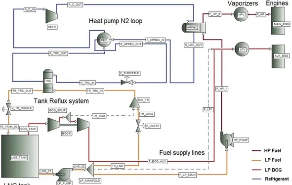
Figure 1: PFD: Processo di pompa di calore, nella versione con BOG alimentato al motore AUX (HeP-AUX)
La Figura illustra l’assetto ottimale del processo (identificato dalla sigla "HeP-AUX"), che prevede di alimentare i motori ausiliari (AUX) per la generazione di potenza elettrica con BOG (a 6 bar) e il motore propulsivo con liquido pompato ad alta pressione. Grazie a tale accorgimento, la pompa di calore é chiamata a
compensare solo la frazione di calore, in ingresso nel serbatoio, che eccede il consumo di BOG da parte degli ausiliari.
Mediante la sigla "HeP" si identifica invece l’assetto che prevede l’alimentazione del liquido a entrambi i tipi di motore. Tale configurazione permette di evitare l’impiego del compressore del BOG, ma si é rivelata svantaggiosa dal punto di vista energetico.
Gli altri processi considerati allo scopo del confronto sono:
• gli scenari in cui tutto il BOG prodotto, o solo l’eccesso al netto degli ausil-iari, viene bruciato nelle Gas Combustion Units (GCU), indicati rispettiva-mente dalle sigle "GCU" e "GCU-AUX";
• la compressione del BOG fino alla pressione di iniezione di 300 bar medi-ante compressore alternativo multistadio ("HPK");
• il processo di "tipo terminal", standard per i grandi terminal di rigassifi-cazione del GNL, che prevede la ricondensazione del BOG nel liquido pom-pato ad una pressione intermedia (es. 6.3 bar) e quindi sottoraffreddato (qui indicato con "MIX-AUX");
• la reliquefazione mediante cicli frigoriferi, progettati per le metaniere ("REL" e "REL-AUX")
Lo scenario di riferimento per le simulazioni é una nave con serbatoio di combustibile da 2200 m3; potenza di crociera del motore propulsivo di 10.94 MW; carico elettrico coperto dagli ausiliari di 450 kW.
Simulazioni e risultati
Il processo di pompa di calore é stato simulato e ottimizzato mediante il soft-ware Aspen HYSYS® . Le variabili primarie di ottimizzazione sono la pressione
di evaporazione e la pressione massima del ciclo. In base a queste, e dato l’effetto utile richiesto, si determina il flusso di refrigerante necessario. In questo stu-dio la pressione di evaporazione é stata fissata ad un valore di 9 bar, determi-nato mediante analisi parametriche, che costituisce l’ottimo compromesso fra la riduzione del rapporto di compressione e il mantenimento di una differenza di temperatura adeguata nell’evaporatore. Il valore ottimale della pressione di mandata del compressore é compreso nel range 59-66 bar. L’influenza di al-tri parameal-tri considerati significativi é stata valutata mediante analisi paramet-riche. Il software é stato utilizzato anche per modellare i processi alternativi, con l’eccezione del ciclo di reliquefazione, le cui prestazioni sono state stimate dai dati in letteratura.
I risultati delle simulazioni di seguito riportati mostrano che i processi piú ef-ficienti, nel caso in esame, sono il processo di compressione (HPK), il processo di pompa di calore (HEP-AUX) e il processo di tipo terminal (MIX-AUX) con un certo vantaggio di quest’ultimo.
Figure 2: Consumo totale di energia primaria del sistema di alimentazione del combustibile, compreso il gas bruciato nelle GCU, espresso come percentuale della potenza termica del mo-tore primario al 100% del NCR. (*Reliquefazione stimato dalla letteratura)
Componenti
Per il ciclo di pompa di calore si é ipotizzato l’utilizzo di scambiatori a piastre, o Shell&Tube laddove la differenza di pressione fra i fluidi lo richiede. Per il compressore del refrigerante si consiglia una macchina alternativa a due stadi non lubrificati, capace di operare ad una temperatura di aspirazione di circa -140°C in uscita dal recuperatore del ciclo. In base al modello di compressione politropica utilizzato la compressione avviene interamente al di sotto della tem-peratura ambiente; il lavoro di compressione é pertanto contenuto, ma si rende necessario l’utilizzo di leghe speciali che aumentano il costo della macchina.
Conclusioni
La tabella seguente riassume un confronto di massima fra i tre processi che of-frono la migliore efficienza energetica a pieno carico. Si osserva che nessuno dei tre é in grado di controllare la produzione di BOG quando il motore princi-pale é spento. L’unico fra i processi esaminati, che consente in tale situazione di evitare di bruciare il BOG, é il processo di reliquefazione, al prezzo di una minore efficienza e una maggiore complessitá.
In conclusione, per quanto riguarda lo scenario in esame, la maggiore com-plessitá impiantistica della pompa di calore ne scoraggia l’impiego in favore del processo di tipo terminal ("MIX-AUX"), nonostante essa si dimostri competitiva con gli altri per quanto riguarda le prestazioni energetiche.
Introduction
Liquefied Natural Gas (LNG) is becoming a competitive marine fuel due to the introduction of stricter environmental standards for marine emissions, and the market for LNG fuelled ships is expected to grow from local short-sea market to deep-sea shipping on a global scale. The recent orders for large LNG fuelled ships reveal the existence of a growing market and the need for more advanced and efficient technological solutions for LNG fuel systems, propulsion systems and handling of LNG Boil-Off-Gas (BOG) generated from heat transfer through the cryogenic tank insulation (heat leak).
The technical literature and the market players seem to have identified the most efficient design for large LNG fuelled ships in the combination of atmospheric fuel tanks and 2-strokes low speed gas diesel engines with gas injection at high pressure (ME-GI). Both systems are established and commercially available tech-nologies, however their combination poses the practical challenge of BOG han-dling that is still not fully resolved, due to the high pressure required by the ME-GI engine.
Many manufacturers and technology providers are currently developing high pressure Fuel Gas Supply System arrangements, but it is still not clear how these will provide a reliable and efficient solution to the BOG issue. The Norwegian company LNG New Technologies patented the concept for a heat pump system
that extracts heat from the cryogenic tanks and discharges it to the vaporizing high pressure LNG directed to the ME-GI engine, thereby controlling the BOG generation in the tank.
The purpose of this thesis is to define a process layout of the above mentioned heat pump concept, optimize it by means of computer simulations, evaluate its performance compared to alternative processes and indicate what kind of pro-cess equipment would be needed.
The background to the work is described in the 2ndchapter of the thesis, which includes an overview of the LNG fuelled ship market, descriptions of the key technologies involved, namely gas engines, cryogenic tanks, BOG handling meth-ods, including reliquefaction cycles, and finally the state of the art of fuel supply solutions for ME-GI engines applications. Chapter 3 is dedicated to the descrip-tion of the proposed heat pump process in its layout details, and to the defini-tion of a specific scenario as a basis for the calculadefini-tions. Chapter 4 presents the computer simulations executed with the commercial software HYSYS®, start-ing from the model structure and inputs, to the simulation results presentation and discussion. This chapter includes a quantitative comparison with alterna-tive BOG handling processes. Finally, chapter 5 outlines a preliminary selection of process equipment on the basis of the simulation results, with particular em-phasis on the heat pump refrigerant compressor.
Background
2.1 LNG as ship fuel
2.1.1 Motivations for LNG as a ship fuel
LNG has been used as a fuel for propulsion on LNG Carriers (LNGC) since 1964, after the introduction of the first LNG fuelled vessel (non-LNGC) in 2000 the last decade has seen LNG becoming a competitive fuel for marine transport, mainly due to the introduction of restrictions in the international environmental regu-lations on marine emissions that favour LNG compared to more conventional and polluting marine fuels.
LNG marine projects certainly demand a higher investment cost than conven-tional projects, related to the tank and fuel gas system, but some savings can be expected on fuel cost depending on the fuel pricing scenarios [39,40], however as fuel price prediction is critical in a long term project the savings associated with emission regulations are currently the main drive for LNG projects in the shipping industry.
The most influential international regulation is the "MARPOL 73/78", outlined by the International Maritime Organization (IMO) in a diplomatic conference in 1973 and expanded since then with six annexes [40, 38]. The last MARPOL Annex VI sets limits for NOxand SOxemissions from exhaust gas, differentiating
from open sea and selected coastal areas denominated Emission Control Areas (ECA). Figure2.1illustrates how the regulations are getting more stringent in the decade 2010-2020, especially in the ECAs. The current global status of the ECAs is illustrated in Figure2.2.
Figure 2.1: Implementation schedule for Revised MARPOL Annex VI [1, p.2]
Figure 2.2: Emission Control Areas under IMO Annex VI [2]
In this context LNG is seen as a viable alternative to the conventional more polluting fuels such as Marine Diesel Oil (MDO) and Heavy Fuel Oil (HFO), for an increasing number of shipping segments.
2.1.2 Ship propulsion alternatives
To date ship propulsion is largely dominated by diesel engines that replaced steam turbines in the course of the 20thcentury, less frequently ships are driven by gas turbines, almost only LNG Carriers are still driven by steam turbines that guarantee flexibility in the fuel mix.
Diesel engines can be classified by the shaft speed: low, medium or high (the latter being limited to very small vessels), or by the number of strokes: 2-strokes (always low speed) or 4-strokes (usually medium speed) [7]. Figure 2.3 relates the thermal efficiency of commercial ship propulsion technologies with the in-stalled power, it results that diesel low speed engines are the most efficient, fol-lowed by medium speed engines, gas turbine cycles and lastly steam turbines.
Figure 2.3: Typical thermal efficiency of prime movers [3, p.244]
All of the options listed above are suitable for LNG Carriers propulsion, some of them also for LNG fuelled ships (non-LNGC). Figure2.4 has been created to offer a more detailed overview of the main propulsion alternatives for LNG fu-elled ships and LNG Carriers, mapping the various technology by type of fuel used. The three vertical boxes in the background indicate the possible fuel modes of the machine, for instance steam turbines cover the three fuel modes
mean-ing that the steam boiler can burn either only natural gas, or a mixture of gas and fuel oil, or only fuel oil (MDO/HFO); low speed engines on the other hand cover only the second two modes since they can not run on pure natural gas and require at least a minimum amount of pilot fuel oil for ignition.
Figure 2.4: Ship propulsion alternatives for Natural Gas fuelled ships and Carriers sorted by type of fuel [4,3,5,6,1,7,8,9,10,11]
The most attractive propulsion alternatives for LNG fuelled ships are recip-rocating engines working in dual fuel mode, most of these machine can run on natural gas with a variable amount of fuel oil and easily switch to fuel oil mode if required. In the current state of the art of small LNG fuelled vessels mainly 4-strokes medium speed engines are employed of the types Dual Fuel and LBSI. The shaft speed of these type of engines is too high for the propeller, therefore the power transmission normally goes through a gear or through electric gener-ators (Figures2.6and2.5).
Figure 2.5: Platform supply vessel, Dual fuel Diesel-Electric propulsion [4]
Figure 2.6: Ro-Ro ship, Pure LNG operation, Diesel-Mechanical propul-sion, with Diesel backup engine [4]
In addition to the superior thermal efficiency, another advantage of low speed engines is that they can match the optimum propeller speed and be directly coupled to the propeller without a reduction gear and without the need for elec-tric generators [41] [42, p.884]. Among those the High Pressure Gas Injected en-gines have high efficiency at all loads thanks to the thermal properties of the Diesel cycle [4], MAN Diesel & Turbo is one of the world leading producer of this type of machines that are gaining popularity in the market of medium-large gas fuelled ships under the name of "ME-GI" engines.
The main disadvantage of ME-GI engines is that the high pressure required for gas injection introduces complications and safety concerns in the design of the Fuel Gas Supply System, to overcome this the competitor company Wartsila offers a low pressure dual fuel 2-stroke solution, with direct gas injection dur-ing the compression phase and pilot fuel injection for ignition of the premixed charge.
The present thesis aims to develop a system specifically fitted to a ME-GI en-gine propelled vessel.
2.1.3 LNG fuelled ships
As of today a number of different categories of ships are being built or designed for LNG propulsion, the primary distinction for LNG fuelled ships divides them
in two groups:
• LNG Carriers (LNGC);
• LNG fuelled ships (other than LNG Carriers).
The first ships to use LNG as a fuel were LNG Carriers, since 1964. All of the early LNG Carriers were driven by steam turbines, fuelled by marine Heavy Fuel Oil (HFO) and LNG BOG from the cargo tanks [43], in the 1980’s started the develop-ment of more efficient internal combustion engines systems for LNGC [4, p.2], in 2006 Slow Speed Diesel engines with BOG reliquefaction systems entered the market, together with Dual Fuel engines and electric propulsion [43, p.3].
In 2000 the first LNG fuelled ship (non-LNGC) started sailing in the norwegian coast [44], since then a number of small ferries and vessels for short-sea routes came into service mostly in Norway [38, p.3] [4, p.2]. Most of the early LNG fuelled vessels were car/passenger ferries, Platform Support Vessels (PSV) and similar short-sea vessels, in the recent years also tankers, cargo vessels and tug boats went into operations.
As of today the last confirmed orders include chemical tankers, cargo vessels as well as Ro-Ro vessels, bulk carriers and container ships [45]. The motivation to power these types of ships with LNG could be related to maximize the sav-ings in ECA zones, as a matter of fact ship traffic analyses indicate that small and medium Ro-Ro vessels, tankers, bulk carriers and container vessels spend considerable time sailing in ECA zones [38, p.5], [46, p.26], . In particular it can be observed that fuel cost accounts for the highest share of the running cost for container vessels among the main shipping segments [47,48] and the industry is showing a particular interest in developing large LNG fuelled container ves-sels for international shipping routes [39,49].
Carri-ers and other LNG fuelled ships is the ratio between the tank size and the power of the propulsion system. This parameter is important when it comes to ana-lyzing and comparing BOG handling alternatives, as the tank size can be con-sidered proportional to the heat leak in the tank and to the BOG flowrate, while the propulsion power is proportional to the fuel consumption of LNG or BOG. It can be observed in Figure 2.7 that the ratio between the LNG tank volume and the installed main engine power is much higher for LNGC, due to the fact that the cargo volume in a LNGC contributes to the total LNG volume and BOG generation.
Figure 2.7: Comparison between LNGC and other LNG fuelled vessels, the blue lines indicate constant ratio between the LNG tank volume and the main engine power, [12, p.9], [13,14,15]
2.2 Tank types
LNG on ships is stored in cryogenic insulated tanks at the temperature of -160 to -162°C. LNG marine tanks have been classified by the IMO in three categories:
characterized by complete secondary barrier;
• Type B tanks
characterized by partial secondary barrier, they typically have a self-supporting structure;
• Type C tanks
characterized by absence of secondary barrier, they are in most cases smaller pressurized tanks.
The first LNG tanks for ships were developed for the cargo on LNG Carriers. Since the LNG fuel on LNGCs is taken directly from the cargo tanks a dedicated LNG fuel tank is not needed, however with the introduction of LNG fuelled ships also dedicated LNG fuel tanks had to be developed.
Currently type C pressurized tanks are the only used for the small existing LNG fuelled ships (non-LNGC) [45]. The advantage of this type of tank is that they can operate at a pressure up to 9 bar, this allows the gas to accumulate in the tank atmosphere for some time before this pressure is reached. The main dis-advantages of Type C tanks are the large amount of dead space and the tank capacity limits (currently in the order of 500 m3) [25, p.13].
It is expected that other types of tanks, different from Type C, will be taken in consideration for larger volumes of LNG fuel [25], for example Germanischer Lloyds estimates that for container ships with LNG volumes larger than 2000-3000 m3 large type B prismatic tanks would be preferable to small Type C tanks due to lower specific costs [39, p.9]. If Type A and B are utilized as fuel tanks in LNG fuelled ships the maximum pressure of about 1.7 bara will provide very little buffer capacity for containing the BOG generated by the heat leak, as a consequence a different BOG handling approach will be needed.
2.3 BOG handling
LNG Boil Off Gas (BOG) is generated in any type of LNG tank due to the heat flow from the environment to the cryogenic tank, this flammable gas rich in Ni-trogen and Methane accumulates in the tank atmosphere above the LNG liquid level at a temperature usually higher than the bulk liquid, causing the tank pres-sure to steadily increase in time. The generation and accumulation of BOG must be controlled to make sure that the tank pressure stays within the limits, in par-ticular a too high pressure could lead to damages to the tank structure.
Depending on the type of tank and the application different BOG handling meth-ods are used alone or in combinations:
• BOG containment in pressurized Type C tanks;
• BOG "flaring" in Gas Combustion Units (GCU);
• BOG as a fuel for ship propulsion;
• BOG as a fuel for Auxiliary engines;
• BOG reliquefaction;
• BOG venting (as a last resource).
As discussed BOG containment is currently the only BOG handling method for LNG fuelled ships non-LNGC, this is an efficient and simple method but its via-bility is limited to modest tank size for short-sea shipping with frequent bunker-ing.
Gas Combustion Units are used on LNG Carriers to dispose of the excess BOG when it exceeds the fuel consumption or the reliquefaction capacity, in these re-actors the gas is burned and the exhaust vented to the atmosphere, this system is the on board equivalent of flaring.
in steam turbine boilers, recently more advanced and efficient propulsion sys-tem have been developed for LNGC where the BOG is burned alone or in a mix-ture with other marine fuels for propelling the ship. Figure2.8) collects the tech-nologies for LNGC propulsion with respect to utilization of BOG.
Figure 2.8: Propulsion systems for LNG Carriers [5, p.5], the highlighted alternative refers to low speed 2 stroke gas injected diesel engines integrated with a high pressure BOG compressor and a reliquefaction cycle
BOG can be used for electric power production if the vessel is equipped with a set of Dual Fuel 4-stroke Diesel Auxiliary engines, however due to the variabil-ity of the Auxiliary power demand on a ship a parallel system would be needed to handle the BOG under all operating scenarios.
2.3.1 BOG reliquefaction on LNG Carriers
On board processes for BOG reliquefaction have been developed for LNG Car-riers, the first plant was built in 2000 and since then a number of different tech-nologies became available on the market (Table2.1).
Table 2.1: Main technologies for reliquefaction of BOG on LNG carriers [10]
Plant model Manufacturer Work Cycle Year Reliq. Capacity [kg/h] Power [kW] Specific work [kWh/kg]
LNG Jamal Osaka Gas Brayton 2000 3000 3000 1
TGE Tractebel Brayton 2004 6250 5030 0.75
Mark I HGS Brayton 2006 6000 5800 0.96
EcoRel Cryostar Brayton 2008 7000 6000 0.86
Mark III HGS Brayton 2008 7000 5500 0.78
Mark III Laby-GI HGS Brayton 2009
TGE Laby-GI Tractebel Cascade 2009
The most common process for on board reliquefaction is the Nitrogen Bray-ton refrigeration cycle, produced by several manufacturers with different lay-outs. Alternatives to the Brayton cycle are the Ethylene/Propylene cascade pro-cess produced by Tractebel Gas Engineering (TGE) and Burckhardt Compres-sion [19, p.24] and the mixed refrigerant MiniLNG plant developed by Sintef.
Nitrogen Brayton cycle
The main manufacturer of Brayton processes for on board BOG reliquefaction is Hamworthy (recently bought by Wartsila). The first version of the Hamworthy process, also known as Moss process, or Hamworthy Mark I, is shown in Figure
2.9, in this process the BOG from the tank is compressed to about 4.5 bar by a two stage centrifugal compressor and reliquefied in the plate fin heat exchanger in the cold box. The cooling medium is pure Nitrogen which is compressed from 13.5 to 57 bar by a centrifugal 3 stage compressor coupled with a single stage turbo expander [10],[3, p.270].
Figure 2.9: Hamworthy 1st generation BOG Reliquefaction System (Mark I) [16, p.5]
A more recent version of this system is the Hamworthy Mark III cycle in Fig-ure 2.10with the main difference that the tank BOG is preheated by HP warm Nitrogen before entering the compressor, as a consequence 3 stages with inter-cooling are required to compress the BOG to its reliquefaction pressure, with the advantage that part of the compression heat can be discharged to the seawater, thereby increasing the overall efficiency [16, p.6]
Figure 2.10: Hamworthy 3rd generation BOG Reliquefaction System (Mark III) [16, p.6]
The Cryostar’s EcoRel process is a different version of a Brayton cycle with distinct heat exchangers of which one internal recuperative Nitrogen heat ex-changer, two separate heat exchanger for BOG desuperheating and liquefaction and one BOG compressor cryogenic intercooler. It can be observed that while Hamworthy moves the BOG compression to the warm temperatures to take ad-vantage of seawater intercooled stages, Cryostar choses to maintain a cold BOG compression (at about 4.8 bar) using the Nitrogen for the intercooling, in paral-lel with the BOG desuperheating.
Figure 2.11: Cryostar EcoRel reliquefaction process for LNG Carriers [17, p.5]
Mini LNG
The Mini LNG system is a mixed refrigerant process that has been developed and tested in the Sintef laboratories in Trondheim, and operated on a small LNGC since 2009 [18]. In this plant configuration the tank BOG is compressed by a oil-free labyrinth compressor to the pressure of 18bara (max 22bara) and above ambient temperature. The warm gas is then cooled by a seawater after-cooler and a Propylene precooling cycle to the temperature of -35°C , before entering the heat exchanger where it is desuperheated, liquefied and subcooled against the Mixed Refrigerant. At this point the subcooled liquid is throttled to tank pressure [50, p.145]. A full scale Mini LNG plant has been installed on a Multigas Carrier by I.M. Skaugen SE, with a capacity of 20 tonnes LNG/day [51] and a energy consumption of 0.7 kWh/kg of reliquefied LNG [29]. The lower value of energy consumption of 0.47 kWh/kg in Table2.2, is due to the fact that the Propylene compressor work is not included in the calculations [29].
Figure 2.12: SINTEF Mini LNG Process, PFD [18, p.34]
Table 2.3: SINTEF Mini LNG Process, performance [18, p.39]
To compare the Mini LNG performance to the one of the process in this study it is useful to estimate its COP. If the refrigeration duty of 70-93 kW is taken from table 2.3, with a mixed refrigerant compressor work of 395 kW [18, p.35] (pre-cooling refrigerant compressor neglected), the resulting COP is 0.18 to 0.24. If refrigeration duty is computed from the BOG mass flow according to the equa-tion
˙
Qr e f = ˙mBOG· ∆hev ap=
20000kg /d a y
24 · 3600 · 517.1k J/kg = 119kW (2.1) then the COP becomes 0.3.
2.4 Systems for 2-Strokes Low Speed Engine Propulsion
The objective of this thesis is to develop a system for LNG fuelled ships equipped with 2-stroke low speed gas diesel engines. There are two reasons why the topic has been restricted to this specific scenario. The main reason is that this type of engines are expected to have a bright outlook in the market of medium-large LNG fuelled ships due to the remarkable propulsion efficiency given by the ther-mal features of the gas diesel cycle and by the possibility of direct coupling to large slow propellers. Secondly the BOG handling is particularly critical in this scenario due to the difficulty of feeding it to the engine at high pressure. In
summary it is expected that providing an efficient and reliable solution for the BOG handling in this scenario would open the way to one of the most efficient propulsion solutions for gas fuelled ships.
In the present chapter the state of the art of ship propulsion systems with 2-stroke gas diesel engines is described, including an overview of the engine tech-nology itself and a series of options for fuel supply that are under development.
2.4.1 ME-GI engines
MAN Diesel & Turbo is one the world leading manufacturers of large low speed gas diesel engines for ship propulsion, these engines are known by the desig-nation "ME-GI", indicating 2-stroke Dual Fuel Electronically controlled Gas In-jected engines. Figure2.13shows the cross section of a ME-GI engine.
Figure 2.13: Sketch of a ME-GI engine [19, p.5]
Figure 2.14: Example of ME-GI Gas supply specifications, delivery pressure at varying engine load, for a 250 bar engine feed [20, p.15]
The attribute "Dual Fuel" indicates that the engine can run on fuel-oil alone or on a mixture of fuel-oil and Natural Gas, the amount of injected fuel-oil can be reduced down to a minimum preset of 2-5% of pilot fuel necessary for
ig-nition, meaning that operation with Natural Gas alone is not possible [19]. The main feature of these machines compared to other Dual Fuel engines is that they always operate in a standard Diesel cycle, the HP gas injection at the end of the compression stroke provides the advantages of the Diesel cycle such as absence of limits for knocking and misfiring, possibility to operate at maximum power and Break Mean Effective Pressure (BMEP) without de-rating and low methane slip [4,52]. The thermal efficiency of about 50% of the gas injected Diesel cycle is comparable to the conventional fuel-oil cycle, this value is high and fairly sta-ble at different gas/fuel-oil ratios and at reduced engine load [20].
The detailed description and modeling of the engine is out of the scope of this thesis, yet this machine sets the requirements for the Fuel Gas Supply System and therefore the boundary conditions for a related simulation model. In par-ticular ME-GI engines require gas at 250-300 bar and about 45°C during normal operation, at reduced load the pressure can be reduced linearly as shown in Fig-ure2.14.
The two available options for supplying Natural Gas to such high pressure are LNG cryogenic pumps or multistage reciprocating BOG compressors.
2.4.2 High Pressure BOG compression
High Pressure (HP) compressors are complex and costly machines compared to HP cryogenic pumps but they offer a direct solution to the BOG handling prob-lem. Burckhardt Compression and MAN are developing a BOG HP compressor system for LNG Carriers with ME-GI propulsion, in a configuration where the HP Fuel Gas Supply System is integrated with reliquefaction processes [19],[10, p.8]. The compressor, with the commercial name Laby-GI, is a five stages re-ciprocating machine, with labyrinth oil-free piston sealing for the first three stages and conventional lubricated piston ring sealing in the last two stages,
[20](Figure2.15).
Figure 2.15: Cross section of the Burckhardt Laby-GI fuel gas compressor for ME-GI engine ap-plications [19, p.21]
This machine is designed to compress large quantities of BOG onboard LNG carriers, in the order of 1,5 kg/s for a 210’000 m3 carrier [20, p.10]), an equiva-lent system for an LNG fuelled ship would have to be scaled down to a flowrate approximately 30 to 50 times smaller than this value.
2.4.3 High Pressure LNG Fuel Gas Supply Systems
When it comes to LNG fuelled vessels, rather than downsizing a solution for the LNGCs segment, many companies have focused in developing new processes that employ standard cryogenic components that are used in the LNG fuelled ships industry or in the LNG terminal industry, adapting them to the HP gas injected engine scenario. Mostly these processes consist in pumping the liq-uid LNG and evaporating it at high pressure, avoiding the HP BOG compression stages. Some of the industries involved in this type of research are Samsung, HGS, TGE, DSME, Cryostar, HHI and MHI [19, p.29].
Cryostar in [19, p.31] identifies the main components of a HP Fuel Gas Supply System (FGSS) for ME-GI engines:
• Reciprocating LNG HP pump with Variable Frequency Drive (VFD);
• Automatic pump control system (to meet engine delivery pressure);
• Buffer volume for pressure pulsations damping.
Figure 2.16 shows this FGSS layout, including a list of potential BOG handling methods that might be required.
Figure 2.16: FGSS with Cryostar’s HP pump solution and BOG handling alternatives [19, p.31]
Hyundai Heavy Industries (HHI) in [21] defines a set of general specifications for HP FGSS for ME-GI engines, the layout suggested in this document is shown in Figure2.17.
Figure 2.17: PFD of HP Fuel Gas Supply System, for a design flowrate of 0.39kg/s [21, p.20]
This system is designed for LNG fuelled ships (non-LNGC) with a 6.5 bar Type C fuel tank and a fuel consumption of 0.39 kg/s of LNG at 100% engine load, compared to the one in Figure 2.17 this layout does not include a HP buffer tank, but is equipped with a Suction drum and Low Pressure (LP) pumps up-stream the HP pumps, these units protect the HP pumps avoiding vapor slip in the pump suction and cavitation. In this configuration the HP vaporizer system is composed by a shell & tube glycol heat exchanger that vaporizes and super-heats the LNG to its target temperature, and a glycol closed loop where the fluid is heated by steam generated in boilers [21].
One example of HP FGSS layout for atmospheric tanks is illustrated in Figure
2.18, this layout differs from Type C applications as it includes a BOG handling system with LP BOG feed to the Auxiliary engines, and a BOG recondenser. The recondenser is a contactor that mixes LNG pumped at LP (4-5 bar, in the cooled region) with LP superheated BOG in a suitable ratio, the output is sub-cooled liquid that can be fed to the HP pump. This component is frequently used for BOG handling in LNG receiving terminals [53].
Figure 2.18: PFD of HP Fuel Gas Supply System for atmospheric tank, equipped with BOG com-pressor and recondenser, proposed by Samsung Heavy Industries [22, p.10], [13, p.18]
Integration of HP Fuel Gas Supply Systems and reliquefaction processes
The idea of using pumps rather than compressors to provide HP fuel to the Main engine has been explored also for the design of LNG Carrier’s Fuel Gas Supply Systems. In this case, given the high BOG production, the FGSS will necessarily have to be integrated with a BOG reliquefaction process.
Hamworthy studied how to optimize its Mark III reliquefaction cycles for ME-GI applications, in the system shown in Figure2.19the FGSS is integrated with the reliquefaction cycle through a heat exchanger named "Optimizer", this compo-nent is part of the Brayton cycle in parallel with the "BOG Preheater" and the cold box, and has the function of recovering part of the low temperature exergy of the cold HP LNG stream with a fraction of the HP Nitrogen stream, thereby enhancing the Brayton cycle efficiency.
Figure 2.19: Integration of HP FGSS and Hamworthy Mark III reliquefaction cycle, published by MAN in [19, p.19]
Wartsila, that acquired Hamworthy in the beginning of 2012, is also studying this system for applications with HP 2-strokes engines, Figure2.20shows a pro-cess similar to the one illustrated above, here the BOG compressor is also used to send gas at 5-6 bar to the Auxiliary engines.
Figure 2.20: Integration of HP FGSS and BOG Reliquefaction System LNGRS (or Hamworthy Mark III), published by Wartsila in [23, p.18]
Heat pump process
The previous chapter outlined a literature review of the most relevant BOG han-dling strategies. The high pressure compression and the reliquefacion processes have been developed for LNG carriers, in principle they could be downsized to meet the requirement of the LNG fuelled ship segment. On the other hand there are reasons to believe that a different approach could be followed when it comes to LNG fuelled ships instead of LNGCs:
• The amount of BOG generated in LNG fuelled ships is roughly 10-100 times less than for a similar size LNGC (Figure2.7);
• Downsizing large reliquefaction processes to meet a significantly lower reliq-uefacion capacity might be uneconomical and inefficient;
• Space and process complexity constraints are tighter on a merchant ship than on a LNGC.
The approach of the present thesis was inspired by the Norwegian company LNG New Technologies that outlined and patented a process to cool the LNG fuel tank and bunkering pipe of a LNG fuelled ship by means of a refrigerant cycle that uses the heat requirement of the HP cold LNG in the FGSS to drive the process. The patented system illustrated in Figure3.1is essentially a heat pump process that transfers heat from the cold fuel tank space (5b) and filling pipe (5a) to the LNG Fuel Supply line (8) directed to the engines. The refrigerant fluid
(1) is a inert gas such as Nitrogen subject to compression in (2) and pressure reduction in (4) via throttle valve or expander [24], it can be noted that heat exchangers with external utilities such as seawater, steam or glycol loops are not included in this layout.
Figure 3.1: Jorn M. Jonas patented heat pump process [24]
The principle of integrating the HP FGSS with the Nitrogen reliquefaction cycle was already investigated by Hamworthy and others as detailed in chapter
2.4.3, the heat pump process as outlined by LNG New Technologies differs from those approaches in the way that it aims to achieve the fullest possible integra-tion between the process streams, until the heat discharge to the environment in the form of external utilities streams is excluded.
In the development of the present thesis, different process layouts than the one suggested by LNG New Technologies were studied but the "philosophy" of full heat integration between the process streams without heat discharge to the en-vironment was maintained as a constant feature, with the intention to assess the limitations of this simple and efficient approach.
3.1 Heat pump process layout (HeP)
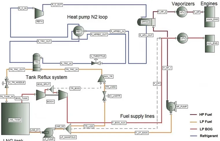
A number of different process layouts have been explored in the course of this thesis, Figure 3.2 illustrates the main configuration of the heat pump process (HeP). The Process Flow Diagram (PFD) is divided in three parts:
• the Fuel Supply lines, that transfer LNG fuel from the cryogenic tank to the main and Auxiliary engines at the prescribed temperature and pressure;
• the Tank Reflux System, that extracts LNG from the tank and recirculates it back at lower temperature;
• the Heat Pump cycle, that transfers the heat from the Tank Reflux System to the Fuel Supply lines, in a closed refrigerant loop.
As indicated by the color legend the heat pump loop contains pure Nitrogen re-frigerant. The Nitrogen, after being compressed by the Refrigerant Compressor, is cooled by the LNG fuel in the High Pressure Fuel Heat Exchanger (HPFHX) in series with the Low Pressure Fuel Heat Exchanger (LPFHX), following the heat discharge to the Fuel Supply lines it enters the Recuperator (REC) for internal heat exchange. At the Recuperator outlet the refrigerant is throttled to a lower pressure in the two phase region, so it can evaporate in the heat exchanger la-beled Tank Reflux Cooler (TRC) providing the necessary cooling duty to the Tank Reflux system. The Fuel Supply lines consist in a HP LNG supply for the main ME-GI engine and a LP LNG supply for the Auxiliary engine. In the present lay-out of the heat pump process (HeP) the BOG is not used to feed the Auxiliary engines (F-BOG-AUX stream is dotted). The Tank Reflux system is fed by LP LNG that is subcooled in the TRC. Alternatively it is possible to recirculate com-pressed BOG in the Tank Reflux system (dotted stream TR-BOG), this option is not covered in this study.
3.1.1 Heat pump with dedicated Tank Reflux pump layout
One feature of the process in figure3.2is that the same LP Pump is used to feed the Auxiliary engine, the HP Pump, and the Tank Reflux system. This design choice has the advantages that it minimizes the number of cryogenic machin-ery items and it allows the pump to always operate above the minimum flow specification characteristic of cryogenic pumps (this is related to the fact that the heat leak in the piping and in the pump body might lead to cavitation in the pump if the flow is too low [54]). On the other hand this configuration has one important disadvantage with respect to the efficiency of the process. The LP Pump needs to work with a outlet pressure of 6 bar for the Auxiliary engine feed, but the required inlet pressure to the Tank Reflux system only needs to com-pensate the pressure drop in the piping, in the TRC heat exchanger and in the tank spray system. A Tank Reflux system pressure higher than required would
increase the specific work of the LP Pump and therefore the enthalpy of the "TR-LNG" stream, yielding to an increased energy input to the tank.
One way to limit this effect is to use a dedicated cryogenic Pump to recirculate the LNG to the tank ("TR-PUMP" in Figure 3.3, with valve "V-LNG-TR" closed) with a lower outlet pressure determined by the pressure drop in the Tank Re-flux system, this option needs to be evaluated comparing the expected gain in efficiency and the added complexity and investment cost of the process, as well as possible operational problems related to the minimum flow specifications of the LP Pump.
Figure 3.3: PFD: Heat pump process, with TR dedicated Pump
3.1.2 Heat pump with BOG fed Auxiliary engine layout (HeP-AUX)
A more relevant change to the layout shown in Figure3.2is to remove the LPFHX and use a BOG Compressor to feed the tank BOG to the Auxiliary engines. This alternative will be interesting if the specific energy consumption for
compress-ing the BOG is low compared to the specific energy consumption of the heat pump process. The advantages of this configuration compared to the one pre-viously described are the following:
• the heat exchanger (LPFHX) can be removed, saving one unit;
• the LP Pump now can work with a much lower outlet pressure, within the limitation of the NPSH required by the HP Pump.
Compared to the layout in Figure3.3this layout requires less units and the Tank Reflux system allows the LP Pump to fulfill the minimum flow requirements.
Figure 3.4: PFD: Heat pump process with BOG fuelled AUX engines (HeP-AUX)
In the course of this thesis the heat pump process (indicated as "HeP", in Figure 3.2) and its version with BOG fuelled AUX engines (indicated as "HeP-AUX", in figure3.4) have been simulated.
3.2 Alternatives to the Heat Pump process
For a quantitative comparison a number of other processes mentioned in the literature review have been simulated and compared to the heat pump process. Table3.1collects the names of these processes, a simple abbreviation to identify them, and indicates whether each engine is fuelled by liquid or vapor.
Table 3.1: Alternative processes
Name Tag Main feed AUX feed description
Base GCU LNG LNG all BOG to GCU
Base + GCU-AUX LNG BOG only excess BOG to GCU
Heat pump HeP LNG LNG
Heat pump + HeP-AUX LNG BOG
HP compressor HPK LNG+BOG BOG similar to Laby-GI
Terminal type MIX-AUX LNG+BOG BOG recondenser at 6.3 bar
Reliquefaction REL LNG LNG estimated from literature
Reliquefaction + REL-AUX LNG BOG estimated from literature
In any of these cases the Auxiliary engine fuel can either be supplied by the LP LNG pump or by a BOG compressor, in the latter case the "-AUX" acronym is attached to the abbreviation.
As a base case the BOG is burnt in Gas Combustion Units (GCU), the simplest improvement that can be made to this configuration is to compress a part of the BOG to the AUX engine feed pressure wasting only the excess BOG (GCU-AUX). The High Pressure compression process (HPK), inspired by the Laby-GI five stage compressor process for LNG carriers, is illustrated in figure3.5.
Figure 3.5: HPK process layout with High Pressure BOG Compressor
The process indicated as "MIX-AUX" resembles LNG regasification terminal processes, where LP subcooled LNG is saturated with compressed BOG in a con-tactor named "Recondenser". The terminal type process illustrated in Figure is similar to the one proposed by Samsung for LNG fuelled vessels (Figure 2.18
from [22]).
Figure 3.6: MIX-AUX process, or "terminal type"
Liquefaction processes have not been simulated in this thesis, the results have been extrapolated from the literature cited in the previous chapter.
3.3 Selection of a reference case
Since the described heat pump process is based on a full integration with dif-ferent systems of a LNG fuelled vessel, its performance is expected to be depen-dent on the proportions between those systems. Therefore a particular effort has been dedicated to adopt a realistic and conservative reference case in order to define the boundary conditions for the process.
From the market trends discussed in chapter2.1.3it appears that there is a need for new BOG handling systems on medium-large LNG fuelled ships for deep-sea routes that require a fuel tank size larger than 2000-3000 m3and spend long time in the Emission Control Areas (ECA). According to these description a generic merchant ships is taken as a reference case, this could correspond to a bulk or chemical carrier, a Ro-Ro vessel or a container vessel.
In order to quantitatively define the reference case, three parameters have been identified as essential to characterize the FGSS and thus set the boundary con-ditions for the heat pump process, namely:
• the tank volume, used to estimate the average heat leak and set a target for the refrigeration duty;
• the Main engine Power, related to the flowrate of HP fuel in the Fuel Supply system and heat pump heat exchanger (HPFHX);
• the Auxiliary engine Power, related to the flowrate of LP fuel in the Fuel Supply system, and to the possibility of directly consuming the BOG at low pressure.
Taking into account the market trends the company LNT [54] suggests as a base case for the process design and optimization a medium size ship with the following characteristics:
• Main engine power during normal voyage: 10.94 MW;
• Aux engine power: 450 kW.
The power of the engines refers to the operation under normal conditions, it is therefore lower than the installed power.
3.3.1 Main engine
It is assumed that the ship is propelled by a single ME-GI main engine with power of 10.94 MW. This value refers to the engine power for driving the pro-peller under normal ship operation, i.e. the condition at which the ship operates most of the time during voyage, engine manufacturers refer to this parameter as "Service Power", or "Normal Continuous Rating" (NCR), or "continuous Ser-vice rating for Propulsion" (SP) [55, p.28]. The NCR is lower than the maximum power that the engine can deliver, for example the NCR is usually 85-90% of the Specified Maximum Continuous Rating (SMCR) that represents the owner’s requirement for the continuous operation of the engine. The SMCR has to be lower or equal to the Nominal Maximum Continuous Rating (NMCR) that is a characteristic of the engine corresponding to the mean effective pressure and engine speed limits in the layout diagram [55, p.29].
In order to perform a correct selection of the Main engine and thereby accu-rately calculate the fuel consumption, the present section refers to studies con-ducted by technology suppliers, and catalogues by the engine manufacturer MAN Diesel&Turbo.
The company Samsung Heavy Industries conducted a comparative study of dif-ferent types of shipping gas engines [13] for A-max (Aframax [56]) oil tankers propulsion, using the ME-GI engine model 6S60ME-GI8.2 [13, p.30], with a NCR of 10,860 kW. This engine corresponds to 6S60ME-C8-GI in the most recent cat-alogue [35, p.53] in figure A.4. According to the MAN designation in figureA.3
this is a 6 cylinders Super long stroke, 60 cm diameter cylinder, Electronically controlled, Compact, Gas Injected engine.
A second study on different fuel gas supply system for LNG carriers has been carried out by MAN Diesel&Turbo for smaller size 5 cylinders engine 5S60ME-C82-GI [14], with a SMCR of 10,000 kW at 105rpm, operating at a NCR equal to 81% of the SMCR. This engine is more similar to the new model 5S60ME-C8-GI in figure A.4 in the appendix. In this thesis, with reference to the similar ex-amples reported above, the 6 cylinders 6S60ME-C8-GI engine was selected to supply the NCR of 10,940 kW. As described in table3.2the SMCR is a fraction of the NMCR, here 85% [57, p.66], also the NCR is 91% of the SMCR and 77% of the NMCR, which gives a Specific Fuel Consumption (SFC) of about 133.1 g/kWh of gas fuel extracted from the datasheet in figureA.4. This fuel consumption for the design fuel LHV in table 4.5, taking into account the pilot fuel, gives a thermal efficiency of the engine of 53%.
Table 3.2: Main engine features Engine 6S60ME-C8-GI NMCR ("L1") 14280 kW SMCR ("M") 12070 kW NCR ("S") 10940 kW SFC (NG) 0,133 kg/kWh SFC (pilot) 0,006 kg/kWh mass flow (NG) 0,404 kg/s thermal efficiency 53 % 3.3.2 Auxiliary engines
Usually 2 or 3 Auxiliary engines are installed on merchant or container vessels for the so called "hotel" consumption, port operations, and other utilities power requirement [7]. The Auxiliary engines’ load during normal operation is ex-pected to be modest, and their fuel consumption is also negligible if compared to the main engine’s. For this study a Auxiliary engines’ power of about 450 kW is chosen as a design value for the normal operation of the ship [54] [14] (Table
fuelled by natural gas at about 6 bara, with injection of Diesel pilot fuel for igni-tion. The Specific Fuel Consumption for the set of Auxiliary engines is expected to be higher than for the main engine, as they are based on the ignition of a premixed charge. Here a SFC of 0.16 kg/kWh is used to calculate the Auxiliary engine fuel flowrate in table3.3, [7].
Table 3.3: Auxiliary engines lumped features
Number of Engines 2 - 4 -Power Installed 2500-3500 kW Normal Power 450 kW SFC (NG) 0,160 kg/kWh SFC (pilot) 0,005 kg/kWh mass flow (NG) 0,020 kg/s thermal efficiency 44 %
3.3.3 Heat leak calculations
The amount of BOG produced in a on board LNG tank during voyage depends on a number of factors, the most relevant are the tank type, size and geometry, the insulation material and thickness Secondly also liquid level, ambient tem-perature and sea state have an influence [27, 34]. An averaged parameter to quantify the production of BOG is the Boil Off Rate (BOR), defined as the per-centage of the total LNG volume evaporating daily. From the data found in the literature it is estimated that the BOR for this size of atmospheric tanks varies between 0.18%/day [54,19] and 0.4%/day [13,26].
Figure 3.7 shows BOR values for vacuum insulated Type C tanks, and atmo-spheric Polyurethane insulated tanks of the same size, as a function of insu-lation thickness.
Figure 3.7: BOR as a function of insulation thickness, tank type and size [25], integrated with data from literature [26,27]
At constant insulation thickness the BOR decreases with the tank volume, due to the increasing ratio between volume of fluid and heat transfer area. Tak-ing into account the typical BOR values from the literature and that a 2200 m3 tank is much smaller than a typical LNG Carrier cargo tank, a BOR value of 0.325 %/day is assumed in the course of this thesis. Based on this value, the mass flow of BOG and the corresponding refrigeration effect required are estimated as de-tailed in Table3.4.
Table 3.4: Calculation of Heat leak for two different scenarios
HeP HeP-AUX UOM
Fuel tank size 2200 2200 m3
BOR 0.325 0.325 %/day
mass flow (BOG) 0.0359 0.0359 kg/s
BOG to AUX 0 0.0200 kg/s
Excess BOG 0.0359 0.0159 kg/s
Q ref required 18.6 8.2 kW
A conservative estimate of the BOG evaporation rate can be obtained by mul-tiplying the BOR with the volume of LNG corresponding to the 95% filled tank, using a density of 457 kg/m3 calculated with HYSYS for the given composition, as in equation3.1.
˙
mBOG =
ρLNG· (Vt ank· 95%) · BOR
24 · 3600 · 100 (3.1)
Assuming that all the heat that leaks into the tank is only absorbed by the phase change of the LNG, the heat leak can be estimated by equation 3.2 [58, p.126].The evaporation enthalpy of 527.1 kJ/kg is an output of the HYSYS reports for the BOG stream at tank pressure.
Ql eak = ˙mBOG· ∆hLNG,ev (3.2)
The goal of the Heat Pump process (HeP) is to supply a refrigeration effect that compensates the estimated heat leak
Qr e fHeP = Ql eak= 18.6kW (3.3)
In case that part of the BOG is compressed for the Auxiliary engine consumption the Heat Pump process (HeP-AUX) needs to cover only a part of the heat leak that corresponds to the excess BOG
Qr e fHeP −AU X = ( ˙mBOG− ˙mAU X) · ∆hLNG,ev = 8.2kW (3.4)
3.4 Refrigerant
The only refrigerant fluid used in the present thesis is pure Nitrogen, the reasons for this choice are:
• Nitrogen changes phase at temperatures that are near to the LNG tank tem-perature (Figure3.8);
• Nitrogen is safe, non-flammable, non-polluting, cheap and available, and already used as inerting fluid in on-board LNG processes.
Figure 3.8: Vapor pressure of pure fluids relevant for LNG processes [28]
Other refrigerants could have been considered, in particular Methane and mix-tures of Nitrogen and Methane, that in principle could be produced onboard mixing Nitrogen with light tank BOG. However introducing flammable com-ponents in the refrigerant mixture would require many additional safety mea-sures (e.g. double wall ventilated piping, gas dangerous designation for valves, flanges, etc...) and increase the plant complexity and cost. This can be accept-able on a LNG Carrier where gas handling systems already exist and the person-nel is trained to operate them, but it is not desirable when it comes to merchant ships [54]. For this reasons these options were not investigated in this thesis.
![Figure 2.4: Ship propulsion alternatives for Natural Gas fuelled ships and Carriers sorted by type of fuel [4, 3, 5, 6, 1, 7, 8, 9, 10, 11]](https://thumb-eu.123doks.com/thumbv2/123dokorg/7516826.105706/24.918.139.782.252.722/figure-ship-propulsion-alternatives-natural-fuelled-carriers-sorted.webp)
![Figure 2.15: Cross section of the Burckhardt Laby-GI fuel gas compressor for ME-GI engine ap- ap-plications [19, p.21]](https://thumb-eu.123doks.com/thumbv2/123dokorg/7516826.105706/39.918.249.670.158.522/figure-cross-section-burckhardt-laby-compressor-engine-plications.webp)
![Figure 2.17: PFD of HP Fuel Gas Supply System, for a design flowrate of 0.39kg/s [21, p.20]](https://thumb-eu.123doks.com/thumbv2/123dokorg/7516826.105706/41.918.113.832.104.423/figure-pfd-hp-fuel-gas-supply-design-flowrate.webp)
![Figure 2.19: Integration of HP FGSS and Hamworthy Mark III reliquefaction cycle, published by MAN in [19, p.19]](https://thumb-eu.123doks.com/thumbv2/123dokorg/7516826.105706/43.918.113.865.112.509/figure-integration-fgss-hamworthy-mark-reliquefaction-cycle-published.webp)
![Figure 2.20: Integration of HP FGSS and BOG Reliquefaction System LNGRS (or Hamworthy Mark III), published by Wartsila in [23, p.18]](https://thumb-eu.123doks.com/thumbv2/123dokorg/7516826.105706/44.918.146.781.106.470/figure-integration-fgss-reliquefaction-lngrs-hamworthy-published-wartsila.webp)
![Figure 3.7: BOR as a function of insulation thickness, tank type and size [25], integrated with data from literature [26, 27]](https://thumb-eu.123doks.com/thumbv2/123dokorg/7516826.105706/58.918.109.851.111.381/figure-bor-function-insulation-thickness-tank-integrated-literature.webp)
![Figure 3.8: Vapor pressure of pure fluids relevant for LNG processes [28]](https://thumb-eu.123doks.com/thumbv2/123dokorg/7516826.105706/60.918.187.732.104.430/figure-vapor-pressure-pure-fluids-relevant-lng-processes.webp)
