F
ACOLTÀ DII
NGEGNERIAR
ELAZIONE PER IL CONSEGUIMENTO DELLALAUREA MAGISTRALE IN
I
NGEGNERIA GESTIONALEMaintenance program for Electric Vehicles power train
by Reliability Centred Maintenance
RELATORI IL CANDIDATO
_________________________
___________________
Prof. Ing. Gino Dini Federico Maccioni
Dipartimento di Ingegneria Meccanica,
Nucleare e della Produzione
_________________________
Prof. Andrew Starr
Cranfield University, School of Applied Science
Manufacturing department - Integrated Maintenance Centre
i
TABLE OF CONTENTS
LIST OF NOTATIONS ... iii
ABSTRACT ... 1 1. INTRODUCTION ... 2 1.1 BACKGROUND ... 2 1.2 WORK OBJECTIVES ... 6 1.3 THESIS STRUCTURE ... 7 2. LITERATURE REVIEW... 8
2.1 STRUCTURE OF A TYPICAL EV POWER TRAIN ... 8
2.1.1 INTRODUCTION ... 8
2.1.2 ICE VEHICLES POWER TRAIN ... 8
2.1.3 ELECTRIC VEHICLES POWER TRAIN ... 10
2.1.3.1 STRUCTURE AND BEHAVIOUR ... 11
2.1.3.2 DRIVE TRAIN CONFIGURATIONS ... 13
2.1.3.3 ULTIMATE SYSTEM SOLUTIONS ... 16
2.2 EV POWER TRAIN: COMPONENTS OPERATIONS, FUNCTIONS AND RBD ... 19
2.2.1 INTRODUCTION ... 19
2.2.2 ELECTRIC MOTOR ... 21
2.2.2.1 ELECTRIC MOTORS: PROS AND CONS ANALYSIS ... 22
2.2.2.2 DIRECT CURRENT (DC) MOTOR ... 24
2.2.2.3 INDUCTION MOTOR DRIVES ... 25
2.2.2.4 PM SYNCHRONOUS MOTOR DRIVES ... 26
2.2.3 EV POWER CONVERTERS ... 29
2.2.4 ELECTRONIC CONTROLLER ... 30
2.2.5 ENERGY SOURCE: BATTERIES ... 32
2.2.6 MAINTENANCE CONCEPTS: RELIABILITY BLOCK DIAGRAM ... 36
2.3 CHAPTER CONCLUSIONS ... 41
3. METHODOLOGY... 43
3.1 INTRODUCTION ... 43
3.2 RCM APPROACH ... 43
3.3 RCM METHOD: FUNDAMENTAL CONCEPTS ... 44
ii
3.3.2 PHASE 2: PM TASKS SELECTION PROCESS ... 51
3.4 RCM ANALYSIS FORMAT: FMECA versus COFA ... 54
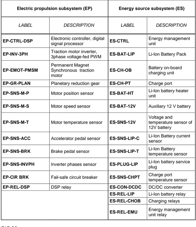
3.5 COMPONENTS LABELLING ... 55
3.6 CHAPTER CONCLUSIONS ... 57
4. RESULTS AND FINDINGS ... 58
4.1 INTRODUCTION ... 58
4.2 COMPONENTS CLASSIFICATION AND EFFECTS OF FAILURES ... 58
4.3 THE MOST IMPORTANT RESULTS ... 61
4.4 DISCUSSION ... 73
4.5 CHAPTER CONCLUSIONS ... 75
5. CONCLUSIONS AND FUTURE DEVELOPMENT ... 76
REFERENCES ... 79
APPENDIX A – COFA worksheet ... 84
iii
LIST OF NOTATIONS
AC Alternating Current DC Direct Current PdM Predictive Maintenance PM Preventive maintenance CM Corrective Maintenance EV Pure-Electric VehicleFCEV Fuel-Cell Electric Vehicles
HEV Hybrid Electric Vehicles
PHEV Plug-In Hybrid Electric Vehicles
ICEV Internal Combustion Engines vehicle
Li-Ion Lithium-ion
Ni-Cd Nickel-Cadmium
Ni-MH Nickel-Metal Hydride
PMSM Permanent Magnet Synchronous Motor
PMBM Permanent Magnet Brushless Motor
DSP Digital Signal Processor
OEM Original Equipment Manufacturers
RCM Reliability centred Maintenance
RBD Reliability Block Diagram
FMECA Failure Mode, Effects and Criticality Analysis
COFA Consequence of Failure Analysis
RTF Run-to-failure component
1
ABSTRACT
The reduction of environmental pollution is one of the greatest challenges for humanity, today and for the immediate future. Air quality is one of the most critical aspects in determining people’s health, particularly in big cities, and transportation emissions are currently considered accountable for almost 32% of total air contamination.
The more widespread use of green vehicles could have important effects both on the environment and the economy, and this thesis work intends to focus on reliability and maintainability of pure-electric vehicles (EVs).
The main objectives of this paper are:
To conduct research into state-of -art of pure-electric car powertrain technology, describing the functions and operations of its various components: mechanical, electrical and the control links between those components are all carefully considered.
To identify and define a long term maintenance plan for the power train system, utilising the RCM method.
In order to achieve these targets and objectives, a wide literature review will be conducted on existing electric vehicle technology, taking already published and available information from similar technologies which are more mature than EVs one, but with comparable run conditions and operations.
The method adopted for this maintenance study is Reliability Centred Maintenance (RCM): this logic will be reviewed and applied to the powertrain system, designing and completing proper worksheets (COFA worksheet and PM task worksheet) which will form the suggested maintenance plan. This proposed plan consists of various elements including: failure modes identification, failure effects on the vehicle, criticality classification of the components, failure causes identification and suggested preventive maintenance tasks with proper periodicity.
In the final part of the paper, the results and outcomes of the analysis will be discussed, and possible future developments will be identified.
2
Chapter 1
1. INTRODUCTION
1.1 BACKGROUND
The large number of automobiles currently in use around the world is one of the major causes of environmental pollution and energy problems: air pollution, global warming and consumption of Earth’s petroleum resources are the main consequences and contributing effects of the rapid development and expansion of the conventional automotive industry.
In an internal combustion engine, the energy is supplied by the combustion of hydrocarbon fuels and the reaction products are released into the atmosphere. The more toxic molecules to human health are nitrogen oxides (NOx), carbon monoxides (CO), and unburned hydrocarbons. [1] [2] Global warming is the result of the “greenhouse effect” induced by high concentrations of carbon dioxide and other gases in the atmosphere. Many human activities contribute towards this phenomenon, and transportation accounts for a large share (32% from 1980 to 1999) of carbon dioxide emissions.
FIGURE 1.1
Carbon dioxide emission distribution 1980 – 1999 [3]
In recent decades, research activity has focused on the development of alternative transportations, with qualities like high efficiency, reduction of emission, and use of unconventional energy sources.
32% 19% 15% 34% Transportation Residential Commercial Industrial
3
FIGURE 1.2
Carbon dioxide emissions from energy consumption by End-Use sector, 1949-2010 [4]
As shown in the above figure, the production of CO2 in the environment tends to increase year on year in all the considered human circumstances, such as industrial activity, residential, commercial and transportation. Furthermore, the system of transportation is particularly critical in effecting human health because it produces air pollution directly in the place where people live, which can result in serious effects upon the quality of life.
Considering pure-electric vehicles (EVs), even if the production of electricity is still mostly supplied by fossil fuels, there are several advantages among the utilization of petrol as vehicle fuel:
- The power plants are usually located far from cities and urban centers;
- The efficiency of power plants is higher than transportation vehicles, which is a base condition to save energy sources;
- Power plants are equipped with systems for the reduction of pollution which are more effective than vehicles, in particular, old vehicles and trucks. Only coal plants utilization could increase the emission of NOx, SOx and particulates, with some potential negative consequences for air acidification. These impacts would reduce over time if greater
4
proportions of renewable power were introduced and the amounts of cold generation were reduced.
Electric vehicles have zero emissions at the point of use, so-called ‘tank-to-wheel’, when powered solely by the battery. The ‘well-to-wheel’ concept includes the CO2 emissions during electricity generation, which depends on the current mixture of fuels used to make the electricity for the grid. To make a correct comparison with emissions from all cars, you have to use the ‘well to wheel’ concept, which includes the CO2 emissions during production, refining and distribution of petrol/diesel.
On a comparable basis taking into account both electricity generation and the processes necessary to deliver petrol and diesel to the vehicle, emission factors and lifetime carbon use have been calculated for vehicles manufactured in 2010, 2020 and 2030. For ICEVs, the addition of pre-combustion emissions (extraction, refining, transport, etc.) typically adds another 10-18% to the ‘tank to wheel’ figure. The table below presents these ‘well to wheel’ figures.
Vehicle manufactured in 2010
EV ICEV
GaBi 4 factors grid mix1 Petrol Diesel
Emission factor well to wheel gCO2/km
106 172 156
Lifetime vehicle carbon use
kg CO2 - equiv
19,161 30,916 28,012
Vehicle manufactured in 2020
Emission factor well to wheel gCO2/km
56 144 130
Lifetime vehicle carbon use
kg CO2 - equiv
10,132 25,864 23,435
Vehicle manufactured in 2030
Emission factor well to wheel gCO2/km
41 120 109
Lifetime vehicle carbon use
kg CO2 - equiv
7,390 21,639 19,606
TAB. 1.1
Comparison of an EV and an ICEV over the Vehicle Life (defined as 180,000 km) [5]
1 GaBi 4 is a Life Cycle Assessment tool conforming to the ISO 14040 Life Cycle Assessment (LCA) standards. It is
designed to allow the user to model the whole life cycle (or part) of a product or service, and provides a quantitative output on a range of environmental impacts.
5
As electricity production decarbonises through an increase in low carbon generation, the overall emission figure for running an EV will drop further. The current lowest emitting ICEV produces tailpipe (tank to wheel) emissions of 86g CO2/km [6]. Adding the average ‘well to tank’ proportion (which starts at 10% and equates to 8.6g CO2/km) means ICEVs can achieve ‘well to wheel’ emissions as low as 94.6g CO2/km and ICE vehicles are being refined to further reduce the ‘tank to wheel’ emissions.
It is worth noting that the standard industry metrics only consider CO2 emissions. However, tailpipe emissions include oxides of nitrogen (NOx) and particulate matter (tiny particles of solid or liquid matter suspended in a gas or liquid) which furthermore contribute to air pollution. This is why vehicle manufacturers are striving to reduce tailpipe emissions and why any vehicle operating solely on battery power can play a significant role in improving local air quality. [6]
In a world where environmental protection and energy conservation are ever more critical, the development of green transportation technology has taken on an accelerated pace and Electric Vehicles, Hybrid electric vehicles (HEVs) and Fuel cell vehicles are typically proposed to replace the ICE vehicles in the near future [7].
6
1.2 WORK OBJECTIVES
The main objective of this thesis work is to produce a maintenance program for the modern EVs power train, consisting in both the traction system and the energy source system. The focus of this program is on electronic control units, communication units and traction power units. The auxiliary system and cooling system analysis is not within the scope of this paper: the purpose is to produce an applicable and effective maintenance program, and the research strategy has been to concentrate the resources in the traction-power subsystem, instead of the whole system.
The maintenance study is based on the Reliability Centred Maintenance (RCM) method: in the chapter 3 Methodology, the principals of this method are further described and discussed.
The objectives proposed to be achieved on this thesis are:
1.
Analysis and understanding of the typical architecture of the electric car powertrain.1.1. Description and schematic drawing of the structure of a typical electric car power train representing mechanical, electrical and control links between components;
1.2. Description of structure and operations of each system component;
1.3. Reliability Block Diagram for general reliability considerations on the whole system.
2.
Identification of the best maintenance strategy for the power train system, employing the RCM method. Definition of a long-term maintenance plan.2.1. Identification of functions, functional failures, failure modes, and criticality classification of each powertrain component;
2.2. For each component (except for run-to-failure2 ones), identification of failure causes, definition of the proper Preventive Maintenance tasks and related periodicity.
2
Run-to-failure are those components which can be replaced after the occurrence of their failure, without preventive maintenance activities.
7
1.3 THESIS STRUCTURE
The Chapter 2 will focus on a literature review of the technology related to electric traction, electronic control system and energy storage system, and it refers to the first macro-objective. Different configurations will be compared through a pros-and-cons analysis and the complete scheme of the power train system will be drawn.
The methodology of the research will be reported in Chapter 3, and in this section the Reliability Centred Maintenance logic will be described: it is the method applied to the power train to produce a maintenance program (ref. Appendix A and B). The RCM principles will be defined, the reliability analysis process will be planned and the maintenance worksheets (COFA worksheet and
PM task worksheet) will be designed.
The core section of the thesis work forms Chapter 4, in which the overall results and findings are described. In this part, the second objective of the research, the identification of the best maintenance strategy for the powertrain and definition of a long-term maintenance plan, is reviewed and presented. In particular, the outcomes of six interesting components will be widely described.
Finally, in Chapter 5, the results and outcomes of the analysis and possible future developments will be discussed.
8
Chapter 2
2. LITERATURE REVIEW
2.1 STRUCTURE OF A TYPICAL EV POWER TRAIN
2.1.1 INTRODUCTION
The conventional vehicles employ a combustion engine for propulsion and the energy source is either liquid petrol or diesel. In contrast, pure-electric vehicles (EVs) use an electric motor for traction, and chemical batteries, fuel cells, ultracapacitors, or flywheels as energy sources3. These vehicle types have different advantages over the internal combustion engine vehicles (ICEVs), such as an absence of emissions, high efficiency, flexible structure, independence from petroleum4 and quiet operation.
This chapter investigates the state of the art of the modern EVs power train structure: describing the operational and fundamental principles, the multiple drive train configurations and the typical system composition by detailed diagrams.
2.1.2 ICE VEHICLES POWER TRAIN
An automotive power train, or drive train, is the electromechanical system that allows the flow of power from the energy source to the road.
Basically, any vehicle power train has four main assignments:
I. Develop sufficient power to match the requirements of the load; II. Carry sufficient energy to support vehicle driving on a target range;
3
Presently achievable energy of ultracapacitors and flywheels can’t be the sole energy sources for EVs.
4
9 III. Demonstrate high efficiency;
IV. Emit limited environmental pollution.
A usual drive train consists of a power plant (engine or electric motor), a clutch in manual transmission or a torque converter in automatic transmission, a gearbox (transmission), final drive, differential, drive shaft, and driven wheels.
In Figure 2.1 represents a schematic drive train of an ICE vehicle.
FIGURE 2.1
Conceptual illustration of an automobile power train [3]
The clutch is used in manual transmission to couple to or decouple the gearbox from the power plant. The torque converter replaces the clutch in automatic transmission: it consists in a hydrodynamic device with a continuously variable gear ratio. The gearbox supply a few gear ratios from its input shaft to its output shaft for the power plant torque-speed profile to meet the demand of vehicle performance: by incorporating both clutch and gearbox, the driver can shift the gear ratio and hence the torque going to wheels. The final drive is usually a pair of gears that reduce further the speed and distribute the torque to each wheel through the differential. Differential is a mechanical device that allows the wheels to have different speed along a curved path, where the outer wheel rotates faster than inner one.
In ICEVs, all the links between these devices are mechanical links and this is why the drive train configuration is not so flexible.
Nowadays more and more significance is given to the environmental impact of the vehicles, emphasizing the development of high efficiency, clean, and safe transportation, able to take place of conventional ICEVs.
10
2.1.3 ELECTRIC VEHICLES POWER TRAIN
Previously, the EV was mainly converted from the existing ICEV by replacing some components with new devices that have the same function, like internal combustion engine with electric motor drive and fuel tank with battery pack, while retaining all the other components, as in following Figure 2.2.
FIGURE 2.2
Primary electric vehicle power train [3]
The lower flexibility, performance degradation, and the heavy weight have caused the use of this type of EV to fade out. To solve this negative aspect, the modern EV is built based on original body and frame design. This solution takes the significant advantage over the “converted” one because it provides the engineer with the flexibility to coordinate and integrate various subsystems so that they can work together efficiently.
Compared with an ICE vehicle, the configuration of an EV is particularly flexible. This is due to several factors. Firstly, the energy flows in the EV is mainly via flexible electrical wires rather than bolted flanges and rigid shafts. Secondly, since the torque-speed characteristic of an engine covers only a narrow range, the required performances of the vehicle have to be achieved through gear changing. On the other side, the electric vehicle propulsion design can be more flexible, namely single or multiple motors, with or without reduction gearing, with or without differential gearing, and axel or wheel motors. Furthermore, EV gives the possibility to choose different energy sources (such as battery and fuel cell) that have
11
different weights, sizes and shapes. The corresponding refuelling system also involves different hardware and mechanism: for example, the battery can be recharged both via conductive or inductive means.
2.1.3.1 STRUCTURE AND BEHAVIOUR
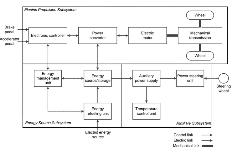
Figure 2.3 shows the general configuration of an EV, consisting of three major subsystems: [8]
Electric motor propulsion; Energy source system; Auxiliary system.
Electronic controller Power converter Electric motor Mechanical transmission Wheel Wheel Energy source/storage Energy refueling unit Energy management unit Auxiliary power supply Temperature control unit Power steering unit
Electric Propulsion Subsystem Electric Propulsion Subsystem
Energy Source Subsystem
Energy Source Subsystem Auxiliary SubsystemAuxiliary Subsystem Brake pedal Brake pedal Accelerator pedal Accelerator pedal Steering wheel Steering wheel Electric energy source Electric energy source Electric link Electric link Control link Control link Mechanical link Mechanical link FIGURE 2.3 General EV configuration
The electric propulsion subsystem consists of the motor drive, transmission device and wheels. The heart of this system is motor drive, comprising of the electric motor, power
12
converter and electronic controller, and the major requirements of the EV motor drive are summarized as follow:
High instant power and high power density;
High torque at low speed for starting and climbing as well as high speed and low torque for cruising;
High efficiency over wide speed and torque ranges;
High reliability and robustness for various vehicle operating conditions;
Reasonable cost.
The energy source subsystem consists of energy source, energy management unit and energy refuelling unit.
The auxiliary subsystem involves the power steering unit, temperature control unit and auxiliary power supply.
Based on the control inputs from the accelerator and brake pedals, the electronic controller provides proper control signals to switch on or off the electronic power converter, which functions to regulate the power flow between the energy source and electric motor. The backward power flow is due to the regenerative braking of the EV and this regenerated energy can be restored to the energy source, provided the energy source is receptive. Notice that most EV batteries as well as ultracapacitors and flywheels readily possess the ability to accept regenerated energy. The energy management unit cooperates with the vehicle controller to control the regenerative braking and its energy recovery. It also works with the energy refueling unit to control the refueling unit, and to monitor the usability of the energy source. The auxiliary power supply provides the necessary power at different voltage levels for all the EV auxiliaries, especially the temperature control and power steering units. [8] Typically, a Permanent Magnet Synchronous brushless motor is selected for a modern EV and the corresponding power converter is a three-phase PWM inverter. In general a Lithium-based (Li-Ion) battery pack is used as energy source, and consequently the refueling unit becomes a battery charger. The temperature control unit consists of a cooler and/or a heater. [3]
13 This typical configuration is shown in Figure 2.4.
DSP voltage-fed inverter PM synchronous motor Fixed reduction & differential Li-Ion Batteries FIGURE 2.4
Typical EV drive train configuration
2.1.3.2 DRIVE TRAIN CONFIGURATIONS
As mentioned above, there is a variety of possible EV configurations, due to the multiple types of propulsion devices and energy sources, and due to the flexibility of electric links. Focusing on the power train shape, in Figure 2.5 are shown six typical alternatives.
2.5.a. Figure 2.5.a shows the configuration of the first alternative, in which an electric motor replaces the IC engine of a conventional vehicle power train. It consists of an electric motor, a clutch, a gearbox and a differential.
2.5.b. With an electric motor, which has constant power in a long speed range, a fixed gearing can replace the multispeed gearbox and reduce the need for a clutch. This configuration not only reduces the weight and size of the mechanical transmission, but also simplifies the drive train control because gear shifting is not required.
2.5.c. The electric motor, the fixed gearing, and the differential device are further integrated into a single assembly, while both axles point at both driving wheels.
14
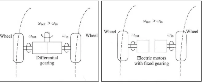
2.5.d. In this configuration the mechanical action of differential is electronically replaced by two electric motors operating a different speed, each of them drives one side wheel.
2.5.e. In order to further shorten the drive train from the electric motor to the driving wheels, the traction motors can be placed inside a wheel (in-wheel drive). A thin planetary gear set can be used to reduce the motor speed and enhance the motor torque.
2.5.f. By fully abandoning any mechanical gearing, the out-rotor of a low-speed electric motor can be directly connected to the driving wheel. Figure 2.5.f shows a gearless arrangement in which the speed control of motor is equivalent to the control of the wheel and hence the vehicle speed. However, this configuration requires the electric motor to have a higher torque to start and accelerate the vehicle.
FIGURE 2.5
Possible EV configuration [8]
As mentioned before, the system configuration of EV propulsion can adopt a single motor or multiple motors, as shown in the following Figure 2.6 and 2.7.
15
Since these two configurations have their individual merits, both of them are adopted in modern EVs but the use of single-motor configuration is still the majority today, for example the new Nissan Leaf and Renault Z.E. fleet. [3] [9] [10]
That choice is explained especially by several reasons:
Costs: the multiple-motor is a completely new configuration and requires a complete redesign of OEMs production plants and consequently very high investments, not justified by the current market demand;
Maintenance benefits: the number of components is inversely related with the reliability of the system, even if in the multiple-motor configuration there is not a differential unit, affected by wear and ageing;
Total weight reduction: the single-motor structure is lighter, even if the multiple-motor one allows a better distribution of the mass of the vehicle. [3] [7]
Electronic controller Power converter Electric motor Transmission Power converter Electric motor Transmission Electronic controller Power converter Electric motor Reduction & differential FIGURE 2.6 Single-motor configuration FIGURE 2.7 Multiple-motor configuration
16
2.1.3.3 ULTIMATE SYSTEM SOLUTIONS
Analysing the configurations showed in Figure 2.5, it is possible to notice a strong evolution from “conventional structures” toward very innovative structures. The major changes are in gearbox and differential concepts.
For ICEVs, there is no alternative to the use of variable gearing, because the torque-speed characteristics of the engine cannot offer the desired performances in a complete driving cycle, such as high torque for hill climbing and high speed for cruising. So primarily, were applied the same concepts to the first electric vehicles. However, the concept of converted electric vehicle is almost obsolete, as it cannot fully utilize the flexibility and potentiality of EVs. Some obsolete theory claimed that variable gearing could also improve the regenerative braking efficacy and the motor efficiency operation over a wide speed range. The modern EVs, with the advances of power electronics and control algorithms, can achieve that aims by electronic means rather than mechanical means. Electric motors can supply the requested vehicle performances and so fixed gearing transmission can replace variable gearing, reducing the overall complexity, size, weight, cost of the transmission and costs of maintenance.
A more controversial aspect is the possibility in EV to replace the differential device, Figures 2.8 and 2.9, with two or even four electric motor coupled to the driving wheels (as anticipated in Figures 2.5.d, 2.5.e and 2.5.f).
FIGURE 2.8 FIGURE 2.9
17
The differential action can be supplied by several motors, controlling the speed of each wheel independently with an electronic control rather than a mechanical device, as in Figure 2.9. In this arrangement, the weight is better distributed than in the conventional one, but negatively, the use of double motor and power converter causes an increase of initial costs and an increase of number of components, with critical consequences in reliability. Nowadays thanks to the low-cost electronic technology, it is possible to find solutions that increase the reliability level, for example using redundant microprocessor in the electronic controller.
The ultimate solution in EVs configurations is the in-wheel drives, as shown in the relative configurations in Figure 2.5.e and 2.5.f. By placing the motor inside the wheel, there is the advantage of minimizing or even removing any mechanical transmission path between motor and wheel.
If using a speed inner-rotor motor (represented in the following Figure 2.10.a), a high-speed reduction becomes necessary to attain a realistic wheel high-speed. On the other hand, the transmission can be totally removed when a low-speed outer-rotor motor is used: in this case, the outer rotor itself is the wheel rim, and no gears are required (Figure 2.10.b).
Both these solutions could be applied to modern EVs: the high-speed inner-rotor motor has the advantage of smaller size, lighter weight and lower cost, but needs an additional planetary gear set; the low-speed outer-rotor motor has the great advantage of gearless and simplicity but it is heavier, bigger in size and more expensive.
18
FIGURE 2.10
19
2.2 EV POWER TRAIN: COMPONENTS OPERATIONS, FUNCTIONS
AND RBD
2.2.1 INTRODUCTION
This section consists in an overview on the modern electric cars propulsion system configurations: several combinations of units offer different possibilities of power train structure. The most proper electric motor drives are compared and described in their operations and main characteristics. The technologies of power converter and energy source are overviewed, as well as the modern possibilities of electronic control systems. A base evaluation of the reliability of the entire power train is made by the Reliability Block Diagram (RBD).
The electric propulsion subsystem is the heart of EVs. Its role is to link energy source to wheels, converting electric energy in vehicle motion with high efficiency and matching the required performances.
It consists of:
electric motor;
electronic controller;
power converter.
Electric motor supplies mechanical energy converting electric one from batteries to wheels, and can generate electricity during the braking phase to recharge energy storage. Regenerative braking is a key process for EV appeal because it enhances vehicle efficiency of between 20 - 25 %.
The power converter supplies the electric motor with the appropriate current and voltage.
Electronic controller provides control signals to power converter and so it controls the electric motor behaviour in order to achieve the requested torque and speed, according to commands from the driver. [8] [11]
In the following Figure 2.11, the functional block diagram of electric propulsion system is shown, listing some possible devices used for each unit.
20
Electronic controller Power
converter Electric motor Transmission / differential Battery pack Wheel Wheel Software VVVF FOC MRAC STC VSC NNC Fuzzy Hardware µprocessor µcontroller DSP Transputer Device GTO BJT MOSFET IGBT MCT Topology Chopper Inverter PWM Resonant Type DC IM SRM PMSM PMBM PMHM Type LEAD-ACID NICKEL-based ZINK-ALOGEN METAL-AIR LITHIUM-based FIGURE 2.11
Functional block diagram of an EV propulsion system: technical options for each function.
The choice of components and shape mainly depends on three factors: user driver expectation, vehicle constraints and energy source.
Driver expectation depends on performance and driving cycle: automobile manufacturers have to take into account that customers will compare ICEVs performances with EVs ones.
Vehicle constraints are linked with vehicle type, vehicle weight and payload.
Electric propulsion subsystem depends on what kind of source is adopted, such as batteries, ultracapacitors, flywheels, fuel cells and various hybrid sources.
21
2.2.2 ELECTRIC MOTOR
The operations requested to the vehicle motor vary widely during a normal drive cycle: frequent start/stop, high rate of acceleration/deceleration (overcoming or braking phase), high torque at slow speed (hill climbing), high speed at low torque (cruising highways).
For these reasons, motors for EV form an individual class, quite different from industrial devices, which operate on a narrow range of conditions.
Industrial motors are generally optimized at rated torque and speed; while EVs need to match four/five times the nominal torque and speed for temporary acceleration and for cruising. Furthermore, industrial motors work usually in fixed place instead of mobile vehicles with harsh operating conditions such as high temperature, frequent vibrations and bad weather.
The motor drives for EVs can be classified as two main groups, namely the commutator motors and commutatorless motors, as shown in Figure 2.12.
The former refer mainly to the classical DC (direct current) motors, which need commutators and brushes to feed current into the armature, making them less reliable and suitable for maintenance-free and high speed. Nevertheless, in recent past DC motors have been prominent thanks to their mature technology and simple control.
With technological progress, commutatorless motors are now more attractive than the conventional. Advantages include higher efficiency, higher power density, lower operating costs, greater reliability and maintenance-free. In fact, the absence of brushes and commutator increases widely the reliability of the motors and reduces failure probability. [8]
EV motor Commutator Commutatorless Self-excited Separately -excited SHUNT SERIES PM EXCITED FIELD-EXCITED Syncronous Induction PM brushless dc Switched reluctance PM hybrid SQUIRREL CAGE WOUND-ROTOR PM ROTOR RELUCTANCE WOUND-ROTOR FIGURE 2.12 Classification of EV motors
22
2.2.2.1 ELECTRIC MOTORS: PROS AND CONS ANALYSIS
The most proper motors in modern EVs are Induction motors, PM Synchronous motors, Switched Reluctance motors and PM Hybrid motors.
Induction motor
It is a widely accepted type of device for EV propulsion thanks to its low cost, high reliability and maintenance free, and at present, it is one of the most mature technologies among various commutatorless motor drives. The main advantages of this type of device are: [12]
Light weight
Small volume
Low initial cost
High efficiency
Low maintenance
These strengths can outweigh the major weakness of induction motors, namely the control complexity.
Permanent Magnet synchronous motors
By simply replacing the field winding of a DC motor with permanent magnets, PM synchronous motors can eliminate conventional brushes, slip-rings and field copper losses. The major advantages of this kind of motor are: [3] [12]
High efficiency
Compactness
Ease of control
Low maintenance
However, it presents also several drawbacks:
High initial cost
23
Magnet demagnetization
Small speed range
Switched reluctance motors
SR motors have been recognized to have big potential for EV propulsion. They have the definite merits of: [3]
Simple structure
Low initial cost
Proper torque-speed characteristics
Although they hold these advantages, there are also some weaknesses:
Design complexity
Control complexity
Acoustic noises
PM Hybrid motor
There are different kinds of hybridization, namely the PM and reluctance hybrid, the PM and hysteresis hybrid, and the PM and field-winding hybrid. Each type has particular advantages that are summarised as: [3]
High efficiency
High power density
Wide speed range
Ease of control
Low maintenance
Quiet operation
24
In Tab.1, the results of a comparative analysis by a grading system are depicted: each type of motor is evaluated for six major characteristics from 1 to 5 points. At the end of each column, there is the final rating: induction motor and PM brushless motors are the most relatively acceptable for EV driving. On the other hand, conventional DC motors are leaving their leadership to the modern solutions. [3][12]
DC motor Induction motor PM brushless motor SR motor PM hybrid motor Power density 2.5 3.5 5 3.5 4 Efficiency 2.5 3.5 5 3.5 5 Controllability 5 3 4 3 4 Reliability 3 5 4 5 4 Maturity 5 5 4 4 3 Cost 4 5 3 4 3 Total 22 25 25 23 23 TAB. 2.1 Evaluation of EV motors [8]
2.2.2.2 DIRECT CURRENT (DC) MOTOR
The DC motors are classified in two categories: wound-field motor and PM motor. In the former, magnetic field is produced by a set of winding and it can be controlled by the dc current, in the latter magnetic field is made by permanent magnets and it is uncontrollable. Traditionally this type of motor has been widely adopted in cases requiring adjustable speed, frequent start/stop, braking and reversing.
The torque is produced by the Lorentz principle, which states that any current-carrying conductor placed within an external magnetic field (B) generates a force (F). If the conductor is a coil, than there is a torque, as shown in Figure 2.13.
In order to keep the same direction of rotation, DC motors need commutators and brushes, which periodically reverse current direction between rotor and stator. These components cause the principal drawbacks of this kind of motor: commutators limit the motor speed and generate torque ripples; brushes are responsible for friction and wear, so that periodic maintenance is definitely required. Nevertheless, DC motor has been the most used device for vehicle propulsion for years, especially thanks to its controllability.
25
FIGURE 2.13
Operation principle of a DC motor [3]
In EV starting operation, from zero to base speed, rotor coil voltage must be increased proportionally with the increase of speed (Armature Control). At the base speed, the armature voltage reaches the rated value and cannot be further increased. In order to reach higher speed it is possible to weaken the magnetic field (Field Control), keeping constant armature current. The torque produced drops parabolically with the increase of speed and the output power remains constant, as shown in Figure 2.14. [12]
2.2.2.3 INDUCTION MOTOR DRIVES
In order to overcome the weaknesses of conventional DC motors, one of the most mature alternatives available is the induction motor drive (IM). It is a type of AC motor (alternative current) where power is supplied to the rotor by electromagnetic induction. There are two typology of IMs namely wound-rotor and squirrel cage. Because of high cost and high maintenance, the former is less attractive than the latter, especially for EV drive train. [3]
Induction motor has some important advantages as low cost, ruggedness, easy maintenance, lightweight and high efficiency. On the other hand, the principal problem is the complexity of speed control, which can be solved only with advanced electronic technology and modern control solutions, increasing the total cost of propulsion system.
FIGURE 2.14
26
FIGURE 2.15
Operation principle of an Induction Motor [12]
2.2.2.4 PM SYNCHRONOUS MOTOR DRIVES
Considering the waveform feeding into the PM motors, they can be classified into two categories:
PM DC motor drive;
PM AC motor drive.
Because of the absence of brushes and commutators, the latter is usually named PM brushless motor drive. This kind of drives is the most capable to compete with induction motor drives for electric propulsion. Their advantages are summarized as following: [12]
Since the magnetic field is excited by high-energy PMs, the weight and volume can be reduced for a given output power (higher power density);
Greater efficiency than induction motor, thanks to the absence of rotor copper losses;
Since the heat mainly originates in the stator, it can be more easily dissipated;
Higher reliability, since PM excitation presents low risks of manufacturing defects, overheating or mechanical damage.
The system configuration of PM brushless motor drives is similar to that of induction motors, such as single or multiple motors configuration. Basically, the single-motor configuration
27
consists of a PM brushless motor, a voltage-fed inverter, an electronic controller and reduction & differential gears.
Compared with the induction motor solution, there is a further difference: the PM brushless motor is not restricted to be three-phase. In fact, a higher number of phases allows reducing phase current and current rating of power devices.
PM AC motor drives can be further classified in three categories:
PM synchronous motor (PMSM);
PM brushless dc motor (PMBM);
PM hybrid motors (PMHM).
The first two typologies are much more mature for electric propulsion utilization.
The Motor control system
PMSMs are fed by sinusoidal ac waves and use continuous rotor-position feedback signal to control the commutation, whereas PMBMs are fed by rectangular ac wave and use discreet rotor position feedback signals to control the commutation.
Because of the rectangular interaction between flux and current, the PMBM has the ability to produce larger torque and, by specially arranging the stator winding and flux path, it has superior dynamic performance and flexible controllability. In particular, the easier control system is one of the principal reasons to choice a PM AC motor drive instead of an induction one. [3] [8]
FIGURE 2.16
28
In Figure 2.16 a torque and speed control scheme is shown for a PM brushless motor drive. Torque, speed and current controller functions are embedded in the Electronic Controller module of EV (DSP). The desired speed ωr* is compared with the motor speed ωr, identified
by a sensor, then Δωis processed by the speedcontroller producing the commanded torque
T*. The desired current Is* is the result of a simple equation that relates current and torque.
The current controller receives Is* and the motor position information from a position sensor,
and then produces gating signal to control the inverter. By this gate signal, the inverter can produce the required phase current to properly control the electric motor torque. The current controller provides the properly sequenced gating signals to the three-phase inverter while comparing sensed currents to a reference to maintain a constant peak current control: using position information, the commutation sequencer causes the inverter to electronically commutate, acting as the mechanical commutator of a conventional DC machine.
Many high-performance applications include current feedback for torque control. At the minimum, a DC bus current feedback is required to protect the drive and machine from overcurrent. [3]
Early permanent magnet motors suffered from the tendency for the magnets to be demagnetized by the high stator currents during starting, and from a restricted maximum allowable temperature. Much improved versions using high coercivity rare-earth magnets were developed to overcome these problems. [12]
A stumbling block to the actual spread of PM brushless motors is the cost of this kind of rare-earth magnets, but currently, the principal automotive manufacturers are adopting PM Synchronous motors for their electric vehicles traction, as in the cases of Nissan Leaf and Renault Z.E. fleet [9] [10]. For this reason, the maintenance analysis in the following sections of this paper will consider only the PMSM.
29
2.2.3 EV POWER CONVERTERS
A power converter is an electrical device that links energy source with motor, feeding current with the proper characteristics (AC/DC, voltage and frequency). The evolution of power converter topologies normally follows that of power devices, aiming to achieve high power density, high efficiency, high controllability and high reliability (Bose, 1992).
There are several types of power converters, namely ac-dc, ac-ac at the same frequency, ac-ac at different frequencies, dc-dc and dc-ac.
Dc-dc converter are usually named dc choppers, dc-ac are named inverters, which are respectively used for dc motor and ac motor drives.
Inverters are classified into two categories: voltage-fed and current-fed. The former is almost exclusively used for EV propulsion because it has a very simple construction and allows power flow in either direction: the inverter converts direct current (dc) from the car's batteries to alternating current (ac) to drive the electric motor that provides power to the wheels. The inverter also converts ac to dc when it takes power from the motor-generator to recharge the batteries (regenerative braking). [8]
A typical inverter adopted with induction motor or PM brushless motors is a 3-phase voltage-fed PWM inverter. PWM refers to the output waveform.
The electronic scheme of this device is shown in Figure 2.17. This inverter has three legs (S1 and S4, S3 and S6, and S5 and S2) which feed phase a, phase b, and phase c of the induction motor. When the switches S1, S3, and S5 are closed, S4, S6, and S2 are opened, and phases a,
b, and c are supplied with a positive voltage (Vd/2). Similarly, when S1, S3, and S5 are
opened and S4, S6, and S2 are closed, phases a, b, and c are supplied with a negative voltage. All the diodes provide a path for the reverse current of each phase. [3]
FIGURE 2.17
DC/AC three-phase Voltage-fed inverter [3]
30
2.2.4 ELECTRONIC CONTROLLER
The Electronic controller provides control signals to power converter: in this way it’s possible to control the electric motor operations and supply the request torque and speed according to command from the driver. The controller receives feedback signals from the vehicle about load parameters and conditions (actual speed driver request speed, battery status, etc.), it analyzes them and sends output to control behavior and matches the proper performances. The control system is divided into three functional units: sensors, interface circuitry and processor.
Sensors translate physical parameters (such as speed, current level, temperature) into electric signals through the interface circuitry. These signals, after being conditionate, are fed into the microprocessor, which processes them and produces the proper outputs to control the vehicle. Sensors are very critical components from the reliability point of view, because they have to work in contact with stressed devices often at high temperature, increasing the fault probability.
Microelectronics technology has gone through an intense evolution in last thirty years. Modern microelectronic devices can be classified in three categories:
Microprocessors;
Digital signals processors (DSPs);
Microcontrollers.
Microprocessor is the calculator (CPU) of the electronic system, which decodes instructions and controls operations.
DSPs are specialized processors for the fast operational needs of digital signal processing to implement sophisticated control algorithms for high performances motors for electric propulsion [13]. It is a very common solution and a functional scheme of a DSP is shown in Figure 2.18. Further reliability considerations will be discussed in the following Chapter 4.
31
FIGURE 2.18
Digital sugnal processor - block diagram [14]
Microcontroller includes all resources to control the system (CPU, ROM or EPROM, RAM, DMA, timers, A/D and D/A converters and I/O signal ports). This control solution has the definite advantage of compact hardware and smooth software.
A modern example of microcontroller is the Fujitsu MB91580: it offers a 3-phase inverter motor control and an embedded resolver interface for electric and hybrid electric vehicles. The device offers a 12-bit Analog to Digital Converter (ADC) and a 12-bit Resolver to Digital Converter (RDC) to detect motor current and position at high speed and with high resolution. The electric angle of the revolver, which is calculated by the RDC, is latched into dedicated registers and synchronized with the three-phase current detected by the ADC. [15]
32
2.2.5 ENERGY SOURCE: BATTERIES
There is no doubt that the energy source device is the most critical element in the development and spread of modern EVs. In order to compete with ICEVs, energy sources have to offer:
High specific energy: the key parameter related to the driving range;
High specific power: the key parameter related to the acceleration and climbing capability;
Long cycle life: defined as the number of deep-discharge cycles before failure;
High efficiency: defined as the ratio between output energy and input energy;
Low total cost: it consists of initial cost (manufacturing) and running cost (maintenance) and the former is generally dominant the latter. It’s a very sensitive parameter to compete with ICEVs. [8] [16]
There are different kinds of technical solutions, namely rechargeable electrochemical batteries, fuel cells, ultracapacitors, ultrahigh-speed flywheels, and each one presents specific strengths.
At present and in the near future, batteries have been identified as the best solution, thanks to the mature technology and reasonable cost. [17]
Batteries are electrochemical devices which convert chemical energy into electric energy (discharging) and vice versa (charging), so they have both functions of source and storage. Several types of batteries are available in the market, classified into lead-acid battery, nickel-based battery, zinc-halogen battery, metal-air battery, sodium-β battery, and ambient-temperature lithium battery [3].
The US Advanced Battery Consortium (USABC) is a R&D organization composed by US Department of Energy, Ford, Chrysler, General Motors and battery manufacturers, with the objective of fund research on advanced battery technology. This organization has set the long-term performance goals for EV batteries, as shown in Tab. 2.2. [18]
33 Parameter (units) of fully burdened
system
Minimum goals for long term
commercialization Long term goal
Power density (W/L) 460 600
Specific power – discharge
80% DOD/30sec5 (W/kg) 300 400
Specific power – regen
20% DOD/20sec (W/kg) 150 200
Energy density – C/3 discharge
rate6 (Wh/L) 230 300
Specific energy – C/3 discharge rate
(Wh/kg) 150 200
Specific power / specific energy 2 / 1 2 / 1
Total pack size (kWh) 40 40
Life (years) 10 10
Life 80% DOD (Cycles) 1,000 1,000
Power & capacity degradation
(% of rated spec) 20 20
Selling price 25,000 units @ 40 kWh
($/kWh) <150 100 Operating environment (°C) -40 to +50 20% performance loss (10% desired) -40 to +85
Normal recharge time 6 hours
(4 hours desired) 3 to 6 hours
High rate charge
20% - 70% SOC7 in <30min @ 150 W/kg
(<20 min @ 270W/kg desired)
40% - 80% SOC in 15 minutes
Continuous discharge in 1 hour – no failure (% of rated energy
capacity)
75 75
TAB. 2.2
USABC goals for advanced EVs batteries [19]
5 DOD = Depth of Discharge, is the percentage of battery energy spent in the load. [40] 6 C-rate is the charge/discharge rate of a battery [41]
34
USABC aims to make EVs as close in performance to ICEVs as possible and there is no a unique energy device able to completely satisfy these requests. The status of the art of batteries performances is explained in the following Table 2.3.
TAB. 2.3
Status of batteries performances for automotive applications [3]
Lithium is the metal with the lightest atomic weight and the highest negative potential, so it presents very interesting characteristics from an electrochemical point of view. Lithium-based battery allows a high electrochemical potential and provides the largest energy density for weight, providing to EVs the greatest performance characteristics in terms of acceleration and range. Two different technologies are available for lithium-based battery:
Lithium-Polymer (Li-P) Battery
35
The Li-Ion has been identified by many battery manufacturers to be the most promising EV battery: as shown in Tab. 2.3 this energy device presents the higher efficiency rate (>95%), one of the major power density range (200-300 W/Kg), a very high specific energy (80-130 Wh/Kg) and wide life duration (more than 1000 deep-discharge cycles).
During discharging phase, Lithium ions (Li+) are released from the anode and travel through an organic electrolyte toward the cathode. [16]
When the Lithium ions reach the cathode they are quickly incorporated into this material. This process is easily reversible and, thanks to this, lithium-ion batteries can charge and discharge faster than others typologies. In addition, Li-ion batteries produce the same amount of energy of NiMH cell, but they are 40% smaller and half lighter: this is one of the most important aspects considering that energy storage is the heaviest subsystem of the vehicle. Moreover, this allows using twice as many batteries, doubling the amount of energy stored and widely increasing the drive range. [16] [17]
The fast development in battery technology is helping to build EVs increasingly similar for performances to the conventional ICEVs.
36
2.2.6 MAINTENANCE CONCEPTS: RELIABILITY BLOCK DIAGRAM
The Reliability Block Diagram (RBD) is a useful analysis tool to evaluate the reliability of complex systems. By RBD method, the analyst represents by simple blocks the functional components of the system, linking them in serial path or in parallel path respectively if the fault of a single unit affects directly the working of the entire system, or if this fault can be bypassed through an alternative path. The RBD has nothing to do with the functional block diagram of the system behavior: the aim is to represent the reliability relations between components and system.
Each component can reside in one of two mutually exclusive operational states: functioning adequately or failed.
There are some simple rules to produce a Reliability Block Diagram:
1. Each block can represent a subsystem of components, whose reliability could be calculated;
2. Blocks are represented in a serial path if all of them are required to allows entire system to run;
3. Several series of blocks are represented in parallel paths if is enough that one of them is working properly;
4. A failed block can be replaced by a “open circuit”;
5. A block with a 100% reliability can be replaced by a “short circuit”;
6. RBD method refers to a maintenance strategy without repair activities: a failed block is not repaired if the system still works;
7. Blocks failures are independent each other.
37 A A B A D C B A D C B A B B C B C A D A E C B A B C E D
System requires both subsystems, A and B
System requires A or B
System requires A and B, or C and D System requires A or C, and also B or D
System consists of 3 subsystems A, B, C, and requires at least any two of these to
perform correctly
System is sutisfied by any of the following: A and D perform correctly
C and E perform correctly
B and either D or E permorm correctly
System is sutisfied by any of the following:
A and B and C perform correctly D and C perform correctly A and E permorm correctly
FIGURE 2.19
38
There are some rules to calculate the reliability of the whole system, assembling single blocks of the RBD: [20]
The reliability of a serial path of blocks is the product of all blocks reliability;
(1)
Rs (t) = system reliability Ri (t) = component reliability
Reliability of several blocks in different parallel paths is calculated according to the following equation:
(2)
The units in parallel systems are referred to as redundant units, since at least one of the units must succeed for the system to succeed. That’s why adding redundancy is one of several methods of improving system reliability.
In general, reliability of a serial path is lower than that of any of its members; whereas reliability of a parallel system is higher than that of the most reliable block. [20]
Estimation of system reliability is a very critical and complex activity; it’s strictly linked to the failure rate λ(t) of each component and a wide number of failure data is necessary to calculate it with good approximation.
39
The general equation which connects reliability and failure rate of a component is the following:
(3)
This equation can be easily simplified if component has a constant failure rate in the time: this is the case of electronic units which are not affected by wear and so failure probability does not increase over time.
(4)
Electric cars power train consists in major part of electric and electronic units, so maintenance strategy has to consider failure behavior of this kind of components.
Considering electric vehicle configuration from a reliability point of view it’s possible to understand the relationship between components and system, to produce the RBD and evaluate the reliability of the entire structure.
The components of the system are the following:
Digital Signal Processor;
Propulsion battery pack (Li-Ion);
12V auxiliary battery;
Power inverter;
Electric motor drive;
Fixed reduction gearing.
Digital Signal Processor (DSP) is the “brain” of the vehicle; it receives and sends signals to each unit in order to obtain the request performances.
Battery pack is the energy source and energy storage which supplies power to the electric motor.
Auxiliary battery is the energy provider of the auxiliary subsystem (cooler ad heater, steering unit, radio, etc.).
40
Power inverter is the electronic device that links energy source with motor, feeding current with the proper characteristics (AC/DC, voltage and frequency).
Electric motor supplies mechanical energy converting electric one from batteries to wheels. Fixed reduction gearing plays the role of connect electric motor to the wheels shaft.
Considering the behavior of the vehicle, each component is necessary to allow the system to work: without any of these units it’s impossible to have the correct operation. The proper way to show this kind of system is a serial path, as described in the following RBD (Figure 2.20).
Electronic controller and sensors Propulsion battery system 12V auxiliary battery Inverter A.C. Electric Motor Fixed reduction gearing Charging system FIGURE 2.20
EV power train: Reliability Block Diagram
The main weakness is the serial structure: this configuration, with absence of redundancies, underlines a criticality from the reliability point of view: the proper operation of each component is absolutely required to allow the whole system to run. For this reason the reliability of the system is strongly related to the less reliable component of the structure, and consequently, the manufacturing quality of each components and an effective preventive maintenance program are very important.
Considering that great part of the system is composed by electronic and electric components, marked by a constant failure rate, it’s very important to predict the main time between
failures of each of them, in order to apply a preventive maintenance strategy to avoid system
41
2.3 CHAPTER CONCLUSIONS
In this chapter, the structure of a normal ICE car has been shortly introduced in order to explain the first idea of electric vehicles, replacing conventional components with electric ones. Then, several configurations of EVs have been described, with pros and cons analysis of functions and operations. Particular considerations have been reserved to the differential unit and mechanical transmission, identifying the potentiality offered by the new electric propulsion (in-wheel drive and electronic differential).
The scheme of the power train is reported with the main links between components, distinguishing for control, electric and mechanical links, in order to understand clearly the role of each component in relation with the others.
In the second subsection, the components of an EV power train have been described; and different configurations and technical solutions have been compared on their specific features.
In particular, have been analyzed the following parts of a power train:
electric motor;
electronic controller;
power converter;
energy source.
Finally, prime maintenance aspects have been considered and discussed through the Reliability Block Diagram: the system is a serial path and its reliability is strongly related to the less reliable component, according to equation (1).
As result of this literature review, a typical power train configuration (Figure 2.21), currently adopted by OEMs, is so described: a single-motor drive train, mainly consisting in a ≈60-80 kW Permanent Magnets synchronous motor drive, with fixed reduction gearing and differential to transmit power to the wheels; the propulsion energy source and storage consists in a ≈22-24 kWh Li-Ion battery pack [9] [10]. The power converter unit is generally a voltage-fed inverter, controlled by a Digital Signal Processor. Finally, a conventional 12V battery is required to supply the auxiliary subsystem of the vehicle, taking energy from the Li-Ion battery through the DC/DC converter.
42 Digital signal processor 3-phase PWM inverter PM synchronous motor
AC Fixed reduction gearing Wheel Wheel Li-Ion battery pack On-board battery charger DC Energy management unit T/Volt sensor Temp. sensor Auxiliary power supply Cooler and heater Power steering unit Electric Propulsion Subsystem
Energy Source Subsystem Auxiliary Subsystem
Brake pedal Accelerator pedal Steering wheel DC
AC from power grid Electric link
Control link Mechanical link DC/DC converter 12V auxiliary battery Charge port AC Heater Service plug Relay Position sensor Speed sensor Temp. sensor 3-phase current sensor Temp. sensor Relay Relay Relay Circuit breaker FIGURE 2.21
43
Chapter 3
3. METHODOLOGY
3.1 INTRODUCTION
This thesis work started with a literature review of the technology related to electric traction, electronic control system and energy storage system. Different configurations have been considered and compared through a pros-and-cons analysis. Latest academic papers, reference books, industrial publications and individual theses have been studied for understanding the typical failure modes and proper PM tasks of an electric vehicle power train.
Reliability Centred Maintenance (RCM) is the approach used in this analysis to produce a long period maintenance program for electric cars power train. In this section the major reasons for the choice of this method will be explained, its base principles, the logic steps and phases.
3.2 RCM APPROACH
RCM is a logical method to identify and prevent plant failures, according to the formal definition: a process used to determine what must be done to ensure that any physical asset
continues to do what its users want it to do in its present operating context. [21]
Over the past twenty years, maintenance has changed a lot, jointly with the huge increase of number and variety of physical assets (such as plants, equipment and buildings), with the increase of complex structures, new maintenance techniques and new ways of organizing maintenance. Moreover, the growing attention and sensitivity to the safety and environmental effects of equipment failures, trying to keep costs down, is leading maintenance towards a systematic and integrated approach: RCM seems to be the most effective method to face with these challenges.
44
There are several ways to apply the RCM method: different start points of the logical path (i.e. system level or component level) and different analysis tools (i.e. FMECA or COFA), but the common principles of the method are clear. RCM is focused on preserving system
functions, classifying components in categories in order to find the right maintenance tasks to
keep the system available, as close as possible to the 100% threshold.
Furthermore, each RCM approach adopts as its own guideline seven basic questions about the asset or system under review, [21] as follows:
1. What are the functions and associated performance standards of the asset in its present operating context?
2. In what ways does it fail to fulfil its functions? 3. What causes its functional failure?
4. What happen when each failure occurs? 5. In what way does each failure matter?
6. What can be done to predict or prevent each failure?
7. What should be done if a suitable proactive task cannot be found?
In this chapter is presented the logic path, which will be used in the following analysis of the electric cars power train, paying attention to each phase of the method, each single decision step and the structure of the worksheets produced.
3.3 RCM METHOD: FUNDAMENTAL CONCEPTS
The RCM method consists in three macro-phases, each one made by a set of steps: [22]
Phase 1: identify equipment, which are important for the plant’s safety, production and asset protection. These are the parts of the system, which require a preventive maintenance strategy to prevent failure, in order to preserve critical equipment functions.
Phase 2: specify the type of preventive maintenance tasks and the periodicities that should be prescribed to the equipment identified in phase 1.
Phase 3: execute the activities specified in the previous phase and control if the planned scheduling is observed.
![FIGURE 2.10 In-wheel drives [8]](https://thumb-eu.123doks.com/thumbv2/123dokorg/7566775.111148/23.892.110.536.102.1013/figure-in-wheel-drives.webp)
![FIGURE 2.17 DC/AC three-phase Voltage-fed inverter [3]](https://thumb-eu.123doks.com/thumbv2/123dokorg/7566775.111148/34.892.113.608.907.1145/figure-dc-ac-phase-voltage-fed-inverter.webp)