UNIVERSITA’ DELLA CALABRIA Dipartimento di Fisica
Dottorato di Ricerca in
Scienze e Tecnologie Fisiche, Chimiche e dei Materiali
Convenzione Università della Calabria-Consiglio Nazionale delle Ricerche
CICLO XXIX
TITOLO TESI
Innovative fluorinated membranes for water and organic solvent treatment
application
Settore Scientifico Disciplinare CHIM/06 CHIMICA ORGANICA
Coordinatore: Ch.mo Prof. Vincenzo Carbone
Firma _____________________________
Supervisore/Tutor: Ch.mo Prof. Bartolo Gabriele Firma______________________ Dott. Alberto Figoli
Firma______________________
Dottorando: Dott.ssa Claudia Ursino
Contents
Abstract Riassunto Introduction Work objectives 1 Fluoropolymers 2 Fluoropolymers in membranes science 3
Thesis outline 10
References 13
Chapter 1. ECTFE membranes produced by non-toxic diluents for organic solvent filtration separation
1.1 Introduction 17
1.2 Experimental 21
1.2.1 Materials 21
1.2.2 LMP ECTFE solubility tests 22
1.2.3 Polymeric dope solution preparation 22
1.2.4 Preparation of LMP ECTFE membranes and dense films 23
1.2.5 Determination of the binary phase diagram 24
1.3 Membrane characterization 24
1.3.1 Scanning electron microscopy (SEM) 24
1.3.2 Atomic force microscopy (AFM) 24
1.3.3 Contact angle measurements 24
1.3.4 Swelling tests 25
1.3.5 Mechanical tests 25
1.3.6 Porosity 25
1.3.7 Bubble point and pore size distribution 25
1.3.8 Solvent Filtration experiments 27
1.4.1 Determination of the binary phase diagram 27
1.4.2 SEM, AFM and Contact Angle Analyses 28
1.4.3 Membrane properties 32
1.4.5 Mechanical tests, porosity and pore size characterisation 34 1.4.6 Membrane filtration performance in organic solvents 38
1.5 Conclusions 38
References 39
Chapter 2. Effect of citrate-based non-toxic solvents on poly(vinylidene fluoride) membrane preparation via thermally induced phase separation
2.1 Introduction 45
2.2. Experimental 47
2.2.1 Materials 47
2.2.3 Preparation of PVDF flat membranes 48
2.3 Characterization of PVDF membranes 48 2.3.1 FT-IR analysis 49 2.3.2 Crystallinity 49 2.3.3 SEM morphology 49 2.3.4 Porosity 49 2.3.5 Pore size 50
2.3.6 Static contact angle 50
2.3.7 Tensile properties 50
2.3.8 Water flux 51
2.4 Results and discussion 51
2.4.1 Phase diagrams of PVDF/Citroflex systems 51
2.4.2 Membrane morphology studies 53
2.4.3 Membrane properties 58
2.5 Conclusions 63
Chapter 3. Innovative hydrophobic coating of perfluoropolyether (PFPE) on commercial hydrophilic membranes for DCMD application
3.1 Introduction 70
3.2. Experimental 73
3.2.1 Materials 73
3.2.2 Polymeric dope solution preparation 73
3.2.3 Coated membrane preparation by Dip-Coating 73
3.3 Membrane characterization 74
3.3.1 Scanning Electron Microscopy (SEM) 74
3.3.2 Atomic Force Microscopy (AFM) 74
3.3.3 Contact Angle 74
3.3.4 Liquid entry pressure of water measurements (LEPw) 74
3.3.5 Porosity 74
3.3.6 Bubble point and pore size measurement 75
3.3.7 DCMD experiments 75
3.4 Results and Discussion 76
3.4.1 Coated membrane preparation 76
3.4.2 Membranes Characterization 77
3.5 Conclusions 90
References 91
Chapter 4. Development of a novel perfluoropolyether (PFPE)
hydrophobic/hydrophilic coated membranes, for water treatment application
4.1 Introduction 95
4.2. Experimental 97
4.2.1 Materials 97
4.2.2 Polymeric dope solution preparation 97
4.2.3 Coated membrane preparation by Dip-Coating and In-situ polymerization 97
4.3.1 Electron Probe Microanalyzer (EPMA) 98
4.3.2 Atomic Force Microscopy (AFM) 98
4.3.3 Contact Angle 98
4.3.4 Liquid entry pressure of water measurements (LEPw) 98
4.3.5 Porosity 99
4.3.6 Bubble point and pore size measurement 99
4.3.7 Mechanical tests 99
4.3.8 Coating stability 100
4.3.9 DCMD experiments 100
4.4. Results and discussion 101
4.4.1 Coated membrane preparation 101
4.4.2 Membranes Characterization 102
4.5Conclusions 115
References 116
Abstract
The aim of this thesis was to study the use of different types of fluoropolymer in order to prepare membranes for chemical and pharmaceutical applications. In fact, the potential use of fluoropolymeric membranes respect to other materials, at industrial levels, has several advantages such as high mechanical strength, high efficiency and stability. However, the unique properties of these materials such as excellent chemical and thermal strength make them extremely versatile but at the same time very difficult to process. As example, Ethylene-Chlorotrifluoroethylene (ECTFE) is insoluble in common organic solvents, and it can only be processed at high temperature, depending on the solvent used.
In this work, three types of fluoropolymers have been studied, such as low-melting ECTFE (Halar®LMP-ECTFE), poly(vinylidene fluoride) (PVDF grade 1015) and perfluoropolyether (PFPEs) (Fluorolink®AD1700 and Fluorolink®MD700). Moreover, low-toxic solvents for humans and the environment have been appropriately selected and used for first time for solubilising the fluoropolymers of interest.
-The Halar®LMP-ECTFE polymer was studied and characterized in terms of solubility parameters, compared with the standard Halar® ECTFE 901 polymer. In fact, this new grade of Halar® shows comparable properties with standard Halar® (hydrophobicity and mechanical properties), but lower crystallinity and lower melting point. Porous membranes and dense film were produced by thermally induced phase separation (TIPs). Two solvents, Diethyl Adipate (DEA) and Dibutyl Itaconate (DBI), never tested before, were selected. The chemical stability of the dense film was evaluated over time (192h) by swelling tests with aggressive organic solvents. Porous Halar®LMP-ECTFE membranes have been tested for organic solvents ultra- (UF) and nano-filtration (NF), such as methanol, ethanol and dimethylformamide. The results show that Halar®LMP ECTFE membranes are promising candidates to be used in separation processes under harsh conditions, such as chemicals production, purification and processing of food, nutraceuticals products and solvents recycling.
- The influence of three different solvents in the membrane formation, using PVDF 1015 as polymer, was studied. Plasticizers from to Citroflex family, such as acetyl tributylcitrate (ATBC), acetyl triethylcitrate (ATEC) and triethylcitrate (TEC) have been selected and used. In particular ATEC and TEC as solvents, were used for the first time. Membranes were produced by thermally induced phase separation (TIPs) technique. The flat sheet membranes produced have been tested in microfiltration process (MF). These membranes can be used in several industrial applications such as sterilisation and clarification of pharmaceuticals or applied to separate contaminants from the water.
- Perfluoropolyethers (PFPE) (Fluorolink®AD100 and Fluorolink®MD700) studied are new types of PFPE, UV cross-linkable. These PFPE photo-reticulated, have been used for coating commercial hydrophilic membrane, such as polyamide (PA) and polyethersulfone (PES) membranes. The aim of this work was to produce hydrophilic/hydrophobic coated membranes, keeping the morphology of the started membrane, unchanged. The study focused on morphological analysis, and on the influence of coating on the support membrane. The membranes produced, hydrophilic/hydrophobic, were characterized and the coating resistance was evaluated over time by direct contact with several chemical agents. The membranes were then tested, in membrane distillation process for direct contact (DCMD), using both deionized water and 0.6M saline. The results show that these coated membranes can be applied to desalination of seawater and wastewater treatment.
Riassunto
L’elaborato di tesi ha come obbiettivo lo studio di fluoropolimeri per la produzione di membrane adatte ad applicazioni in campo chimico e farmaceutico. L’uso di membrane fluoropolimeriche a livello industriale, presenterebbe diversi vantaggi quali l’elevata resistenza meccanica, l’alta efficienza e stabilità. Le proprietà uniche di questi materiali, quali l’inerzia, l’eccellente resistenza chimica e termica li rendono estremamente versatili ma nello stesso tempo molto difficili da processare. Molti di loro come l’etilenclorotrifluro etilene (ECTFE), sono infatti insolubili nei comuni solventi organici, e sono lavorabili solo ad alte temperature.
Sono stati studiati tre diversi tipi di fluoropolimeri, quali l’ECTFE a basso punto di fusione (Halar® LMP-ECTFE), il polivinilidenfluoruro (PVDF grado 1015) e i perfluoropolieteri (PFPE) (Flurolink®AD1700 e Fluorolink®MD700). Inoltre, per la preparazione delle membrane sono stati selezionati e impiegati solventi, mai testati precedentemente, a ridotta tossicità per l’uomo e per l’ambiente.
-Lo studio sul nuovo polimero Halar® LMP-ECTFE, con basso punto di fusione, ha previsto un’attenta analisi dei parametri di solubilità e un confronto con il polimero standard Halar® ECTFE 901. Infatti la particolarità del nuovo grado di Halar®, LMP-ECTFE, è la capacità di mantenere inalterate le medesime proprietà dello standard Halar® ECTFE 901, quali l’idrofobicità e le proprietà meccaniche, ma essendo meno cristallino presenta un punto di fusione più basso, consentendo di solubilizzarlo a temperature più basse. Le membrane porose e il film denso, sono state prodotte mediante la separazione di fase indotta termicamente (TIPs). Sono stati selezionati e confrontati due nuovi solventi quali il Dietil Adipato (DEA) e Dibutil Itaconato (DBI). La stabilità chimica della membrana è stata valutata nel tempo (192h) attraverso il contatto diretto con solventi aggressivi. Le membrane porose di Halar®LMP-ECTFE sono state testate per la filtrazione di solventi organici, quali metanolo, etanolo e dimetil formammide, comunemente usati nell’industria chimica e farmaceutica. I risultati ottenuti hanno dimostrato che le membrane prodotte con l’Halar®LMP ECTFE, potrebbero essere impiegate nella separazione di composti organici, ad esempio durante la produzione di composti chimici e farmaceutici, nel settore petrolchimico e nel riciclo dei solventi. -Lo studio effettuato con il polimero PVDF 1015, è stato incentrato sull’influenza di tre diversi solventi nella formazione della membrana. Sono stati utilizzati plasticizzanti appartenenti alla famiglia dei Citroflex, quali acetil tributilcitrato (ATBC), acetil trietilcitrato (ATEC) e il trietilcitrato (TEC). In particolare l’ATEC e il TEC non mai stati usati precedentemente nella produzione di membrane mediante la separazione di fase indotta termicamente (TIPs). Le membrane piane prodotte
sono da microfiltrazione (MF) e sono state testate per la purificazione dell’acqua. A livello industriale troverebbero una facile applicazione per la sterilizzazione dei farmaci o per separare i contaminanti dall’acqua.
- I perfluoropolieteri (PFPE) (Fluorolink®AD100 e Fluorolink®MD700) studiati in questo lavoro di tesi, appartengono ad una nuova classe attivabile mediante raggi UV. Questi PFPE foto-reticolabili, sono stati utilizzati per il rivestimento di membrane commerciali, idrofile, come membrane in poliammide (PA) e in polietersulfone (PES). Lo scopo di questo lavoro, è stato quello di conferire a queste membrane di supporto, le proprietà dei PFPE quali l’idrofobicità, lasciando però inalterata la loro morfologia. Lo studio è stato incentrato sull’analisi morfologica, ovvero sull’influenza del rivestimento nella membrana commerciale di supporto. Le membrane prodotte, idrofiliche/idrofobiche sono state caratterizzate e la resistenza del rivestimento è stata valutata nel tempo attraverso il contatto diretto con diversi agenti chimici. Le membrane sono state quindi testate nel processo di distillazione a membrana per contatto diretto (DCMD), usando sia acqua deionizzata che soluzione salina 0.6M per la produzione di acqua ultra-pura. I risultati ottenuti confermano che le membrane prodotte potrebbero essere applicate per la dissalazione dell’acqua marina o per il trattamento di acque reflue o di scarico potenzialmente riutilizzabili in processi industriali
1
Introduction
Work objectives
With technological advancement, membrane technology is steadily growing in various industries due to competitive energy prices and environmental concerns. In fact, membrane processes, lead to several advantages comparing with traditional processes: ease of use, low energy use, the possibility to operate without the addition of chemicals or additives, high ability to separate thermolabile compounds, excellent selectivity of specific components and environmental friendliness. One of the most important aspects of membranes preparation is the starting materials. Several polymers have been used and studied in order to prepare tailored membranes. Consequently, a strong motivation for improving established membrane materials and processes is driving the current research. Near to the research of new materials and techniques, also the attention of the impact of the solvents employed is ingrown. Alternative solvents suitable for green chemistry are those that have low toxicity, are easy to recycle, are inert and do not contaminate the product [1]. The combination of the use innovative materials for membrane preparation, such as fluoropolymers, and the non-toxic solvents are the main research studies of this PhD Thesis.
The aim of the present work is the study of fluoropolymer materials in order to produce several membranes that could be applied in the major area of membranes technology.
The research carried out in the present thesis can be summarized as follows:
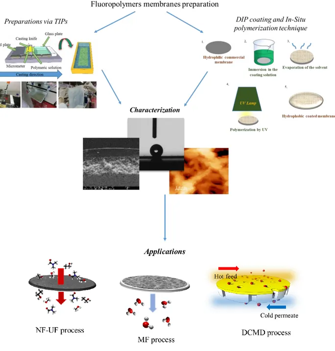
Fluoropolymers membranes preparation via phase inversion or coating procedures using non-toxic solvents.
Characterization tests were carried out in order to study membranes structure and properties.
Fluoropolymers membranes have been applied in different processes in order to evaluate their potentiality in terms of performance such as flux and selectivity towards the species of interest.
2
Figure 1. Schematic illustration of the research carried out in the present PhD Thesis
Fluoropolymers
Fluorinated polymers are produced from alkenes in which some or all hydrogen atoms have been replaced by fluorine (F). These polymers constitute an interesting and unique class of material thanks to the presence of the strong and stable F bond (490 kJ/mol; for comparison: C–H 420 kJ/mol, C-C 340 kJ/mol) [2] on the polymeric backbone. In fact, fluorine is the most abundant halogen, and is the most electronegative and least polarisable element. The influences of the C–F bond, make fluorinated polymers extremely hydrophobic with very low surface tensions, that making them liquid
3
repellent and useful as surfactants. Generally, these polymers have high thermal stability (at high and cryogenic temperatures), photostability, chemical and solvent resistance, properties that increases increasing the fluorine content. However, polymers solubility in solvents usually decreases by increasing the fluorine content of the molecule [3]. Based on the presence or absence of hydrogen atoms (-H) on the structure, fluoropolymers can be divided in perfluorinated (e.g., PTFE, PFA, FEP, etc.) and partially fluorinated (e.g., ECTFE, ETFE, PVDF, etc.) [2,4], Figure 2.
Figure 2. E.g. of chemical structure of a) perfluorinated and b) partially fluorinated fluoropolymers It is possible to divide the fluoroplastics and amorphous fluoropolymers into four categories [2]: 1. High-crystalline, non melt-processable PTFEs
2. Semicrystalline (mp > 80°C), melt-processable fluorothermoplastics 3. Amorphous fluoropolymers with Tg > 70°C
4. Amorphous, curable fluoroelastomers
These important physical and chemical features, including excellent chemical resistance, good mechanical properties, good thermal stability, and ferroelectric, piezoelectric, and dielectric properties, which originated from the low polarity, strong electronegativity and small van der Waals radius, (1.32 A˚) of the fluorine atoms, have made fluoropolymers a material of choice for many industrial and commercial applications.
Fluoropolymers in membranes science
Membranes production is one of the several areas where fluoropolymers have found widespread application. In fact membranes applications have been used in a large variety of processes such as separation of industrial chemicals, water desalination, waste water treatment, removal of micropollutents, pharmaceutical (enzymes, antibiotics, pyrogens), removal of VOC’s, gas separation,
4
etc.. Membranes were simply defined as a selective barrier between two phases. Thanks to their versatility can be applied in separation, fractionation and concentration applications [5]. For all these processes, the performance limits are clearly determined by the membrane itself and the choice of the polymer play a crucial role. Fluoropolymers, as reported above, exhibit many desirable properties for a much wider range of applications in membrane processes, some examples are listed in table 1. Table 1. Examples of typical fluoropolymer used in membrane processes
POLYMER MEMBRANE PROCESS
PVDF poly(vinylidene fluoride)
Homo- and copolymer
MF, UF, MD, PV, fuel cell, Lithium ion battery, tissue regeneration
ECTFE poly(ethylene chlorotrifluoroethylene)
PV, MF, UF, NF
PTFE poly(tetrafluoroethylene)
Homo- and copolymer
MD, PV, MGA, Fuel cell
*MF: Microfiltration; UF: Ultrafiltration; MD: Membrane Distillation; PV: Pervaporation; NF: Nanofiltration; MGA: Membrane Gas Absorption;
Depending of the polymer workability, phase inversion, electro-spinning, sintering, stretching, track etching, as techniques can be applied in order to produce fluoropolymer membranes. Phase inversion methods is the most commonly technique used, thanks to their simplicity and flexible production scales [6]. The concept of phase inversion or phase separation covers a range of different techniques, such as vapor induced phase separation (VIPS), evaporation induced phase separation (EIPs), non-solvent induced phase separation (NIPs) and thermally induced phase separation (TIPs) [7]. Among these techniques, TIPs and NIPs are the two most commonly employed methods in order to prepare polymeric membranes including fluoropolymer membranes.The major difference between NIPs and TIPS is that TIPs processes requires thermal energy to convert the solution into a two-phase mixture, while the one involves an exchange between solvent and non-solvent for membrane formation. However, the phase-separation behavior of a fluoropolymer is often complicated by its semi-crystalline nature, in fact its show two types of phase separation processes: liquid-liquid and solid-liquid demixing [8,9]. Furthermore, as a result of their chemical and physical stability, many fluoropolymers, e.g. ECTFE, show difficult processability and are insoluble in many solvents at room temperature. The problem of solubility has been solved increasing the temperatures of work, so is possible prepare membrane via TIPS process.
5
Besides these preparation techniques, the development of coated membranes represents an important approach to functionalise the membranes with tailored properties.
In the present work TIPs, Dip-coating and In situ polymerization as preparation membrane techniques are used and below illustrated.
The synthesis of novel fluoropolymers more processable, the choice of solvent less toxic, the functionalization of membranes via coating technique, represents the new way to prepare tailored fluoropolymers membranes.
TIPs
Thermally induced phase separation technique provide that a homogeneous solution is prepared by dissolving the polymer in a high-boiling-point, low-molecular-weight diluent at high temperature (T1) and then the homogeneous solution is cooled slowly (T2) to induce phase separation [7,10]. The solution separates in two phases, one rich of polymer and the other poor in polymer. The polymer-rich phase solidifies by crystallization, gelation or on passing the glass transition temperature. Generally, solvents used in TIPs processes are called "latent solvent", because they can work to compound as a solvent only at high temperatures, namely, close to the polymer melting point [11]. After demixing is induced, the solvent is removed by extraction using alcohol, evaporation or freeze-drying. Polymer concentration, the selection of solvents, the cooling rate and the quenching conditions are important factors influencing the phase separation process and resulting morphology [9].
Solvents
As mentioned before, fluoropolymers solubility decreases by increasing the fluorine content of the molecule, and usually were dissolved in a high-boiling organic solvents. Traditionally solvents used, are in general phthalates (dimethyl phthalate DMP, dibutyl phthalate DBP, etc.)[11,13], or N-methyl pyrrolidone [11], toxic, teratogenic and reprotoxic solvents. Recently, the attention of industries, from food and agricultural to chemical and pharmaceutical, focused towards the concepts of sustainable development, harmless solvents, eco-friendly production [13]. Despite membranes processes is described as a clean and environmentally friendly technology, often membranes, were produced using toxic solvents. Fortunately, the studied and the publications related to the membranes preparation using harmless solvents, were in exponential growth [14], table 2.
Table 2. List of recently publication about fluoropolymers membranes preparation via TIPs method, using less toxic solvents
6 POLYMER SOLVENT HAZARD STATEMENTS*
RELEVANT TOXICOLOGICAL INFORMATION* YEAR OF PUBBLICATION ECTFE Di-ethyl Phthalate (DEP)
Not a hazardous substance or mixture according to
Regulation (EC) No. 1272/2008. This substance
is not classified as dangerous according to Directive
67/548/EEC
No component of this product present at levels greater than or equal to 0.1% is
identified
as probable or confirmed human carcinogen
by IARC 2016 [15] Glycerol tri-acetate (GTA) ECTFE Di-butyl Sebacate (DBS)
H315 - Causes skin irritation H319 - Causes serious eye
irritation H335 - Causes respiratory
irritation
No component of this product present at levels greater than or equal to 0.1% is
identified
as probable or confirmed human carcinogen by IARC
2016 [16] Tri-phenyl Phosphite
(TPP)
H302 - Harmful if swallowed H315 - Causes skin irritation H317 - Cause an allergic skin
reaction. H319 - Causes serious eye
irritation H410 - Very toxic to aquatic life with long lasting effects
Group 3: The agent (mixture or exposure circumstance) is not classifiable as to its
carcinogenicity to humans
ECTFE Di-ethyl Adipate (DEA)
Not a hazardous substance or mixture according to
Regulation (EC) No. 1272/2008. This substance
is not classified as dangerous according to Directive
67/548/EEC
No component of this product present at levels greater than or equal to 0.1% is
identified
as probable or confirmed human carcinogen
by IARC 2016 [17]
ECTFE Glycerol tri-acetate (GTA)
Not a hazardous substance or mixture according to
Regulation (EC) No. 1272/2008. This substance
is not classified as dangerous according to Directive
67/548/EEC
No component of this product present at levels greater than or equal to 0.1% is
identified
as probable or confirmed human carcinogen
by IARC 2014 [18]
ECTFE Di-ethyl Phthalate (DEP)
Not a hazardous substance or mixture according to
Regulation (EC) No. 1272/2008. This substance
is not classified as dangerous according to Directive
67/548/EEC
No component of this product present at levels greater than or equal to 0.1% is
identified
as probable or confirmed human carcinogen
by IARC 2012 [19]
PVDF
Acetyl tri-Butyl Citrate (ATBC)
Not a hazardous substance or mixture according to
Regulation (EC) No. 1272/2008. This substance
is not classified as dangerous according to Directive
67/548/EEC
No component of this product present at levels greater than or equal to 0.1% is
identified
as probable or confirmed human carcinogen by IARC
7 PVDF Rhodiasolv
PolarClean®
H319 – Causes serious eye
irritation - 2016 [21]
PVDF
γ-Butyrolactone (GBL)
H302 - Harmful if swallowed H318 - Causes serious eye
damage
H336 - May cause drowsiness or dizziness
No component of this product present at levels greater than or equal to 0.1% is
identified
as probable or confirmed human carcinogen by IARC
2015 [22] N-methyl Pyrrolidone
(NMP)
H315 – Causes skin irritation H319 – Causes serious eye
irritation H335 – Causes respiratory
irritation H360D – May damage the
unborn child
Damage to fetus possible
PVDF
Acetyl tri- Butyl Citrate(ATBC)
Not a hazardous substance or mixture according to
Regulation (EC) No. 1272/2008. This substance
is not classified as dangerous according to Directive
67/548/EEC
No component of this product present at levels greater than or equal to 0.1% is
identified
as probable or confirmed human carcinogen
by IARC 2015 [23] Acetyl tri-Ethyl
Citrate (ATEC)
Tri-Ethyl Citrate
(TEC) H332-Harmful if inhaled
PVDF
Glycol monoethyl Ether Acetate
(DCAC)
H319 – Causes serious eye irritation
No component of this product present at levels greater than or equal to 0.1% is
identified
as probable or confirmed human carcinogen
by IARC 2015 [24] Tri-ethyl Phosphate
(TEP)
H302 - Harmful if swallowed H319 – Causes serious eye
irritation
PVDF Tri-Ethylene Glycol di-Acetate
Not a hazardous substance or mixture according to
Regulation (EC) No. 1272/2008. This substance
is not classified as dangerous according to Directive
67/548/EEC
No component of this product present at levels greater than or equal to 0.1% is
identified
as probable or confirmed human carcinogen by IARC
2015 [25]
PVDF
Di-Phenyl
Carbonate (DPC) H302 - Harmful if swallowed
No component of this product present at levels greater than or equal to 0.1% is
identified
as probable or confirmed human carcinogen by IARC
2014 [26] Di-Methyl Acetamide
(DMAc)
H360D – May damage the unborn child H312 + H332 – Harmful in contact with skin or if inhaled
H319 – Causes serious eye
May cause congenital malformation to the fetus,
Presumed human reproductive toxicant Overexposure may cause reproductive
8
disorder(s) based on tests with laboratory animals
PVDF Acetyl tri-Butyl Citrate (ATBC)
Not a hazardous substance or mixture according to
Regulation (EC) No. 1272/2008. This substance
is not classified as dangerous according to Directive
67/548/EEC
No component of this product present at levels greater than or equal to 0.1% is
identified
as probable or confirmed human carcinogen by IARC 2014 [27] 2013 [28] PVDF Tri-ethyl Phosphate (TEP) H302 - Harmful if swallowed H319 – Causes serious eye
irritation
No component of this product present at levels greater than or equal to 0.1% is
identified
as probable or confirmed human carcinogen by IARC
2013 [29]
PVDF Di-Methyl Sulfone (DMSO2)
Not a hazardous substance or mixture according to
Regulation (EC) No. 1272/2008. This substance
is not classified as dangerous according to Directive
67/548/EEC
No component of this product present at levels greater than or equal to 0.1% is
identified
as probable or confirmed human carcinogen by IARC
2013 [30]
* Classification according to regulation (EC) no 1272/2008- http://www.sigmaaldrich.com/italy.html (accessed February 2017)
Functionalization of membranes
During the last decades, membrane processes have been widely used for water treatment in different applications, such as desalination, micro- and -ultrafiltration, reverse osmosis, pervaporation, etc. In order to achieve high-performance membranes and overcome problems, several methods have been developed and studied for modifying and tailoring the membrane surfaces. In fact, membrane functionalization could be the way to minimize undesired interactions, which reduce the membranes performance, or for introducing additional functional groups for improving the selectivity, creating an entirely novel separation functional layer [31], improving chemical and thermal stability. In particular, coated membranes are prepared combining two or more different materials with different properties and they are also named (thin film-) (nano-) composite membranes. In order to produce hydrophobic coating on porous membranes of different configuration (flat and hollow-fiber), fluoropolymers can be used. In general, the preparation of these coatings can be summarized in two basic steps using (i) non-woven or porous membrane polymer support and (ii) deposition/coating of one of more functionalized materials [32]. One important advantage is that each layer can be optimized independently modifying the thickness, the type polymer employed both as the porous support and the selective barrier layer. Several techniques can be applied for preparing these tailor coated membranes and two main coating categories can be identified (Table 3): 1) solution coatings; 2) polymerisation reactions.
9 Table 3. Principal coating methods
Dip-coating
Dip-coating technique is widely used in making composite membranes thanks to its simplicity. In general, the membrane is immersed in a precursor solution. After a fixed time, the membrane is recovered and the excesses of solution is removed and dried. It possible that after immersion the membrane can be exposed at UV or IR radiation if the precursor solution contained a reactive pre-polymer (or monomer) [32]. Membranes obtained by this method present a very thin layer but often dense. The technique is shown schematically in Figure 3.
Figure 3. Simplified scheme of solution coating by dip-coating;
The final thickness of the coated layer can be controlled by the withdrawal speed (immersion time) and the polymer concentration (or pre-polymer or monomer) [33].
COATING METHODS
Solution coating Polymerization reactions
Dip - coating Spin - coating Spray - coating Casting - coating Interfacial polymerization In situ polymerization Plasma polymerization Grafting
10 ________________________
*Parts of this paragraph will be published in Figoli A., Ursino C., Galiano F, chap.10 “Innovative coating membranes for water treatment” in "Nanostructured Materials Membranes"-Pan Stanford Publishing
An equation, derived by Navier-Stokes equation, can be utilized for calculating the final thickness of the coating layer:
Tequ.= 2
3
√
𝜂 𝑣
𝜌𝑔
(1)
Where, Tequ. is the equilibrium thickness, dynamic viscosity, v the withdrawal speed, ρ the solution density and g represents the gravity.
In situ polymerization
In-situ polymerization process is an easy technique where the reactive monomer (or oligomer, or reactive particles), is placed in direct contact on membrane, by casting or immersion, in order to make the polymerization directly on its surface, Figure 4. Polymerization can occur by irradiation, heating, organic initiator or by a catalyst presents in the initial solution.
Figure 4. In-situ polymerization procedure Hydrophobic coating application
Membrane materials determine the interactions of the membrane with water or other chemical species, thus affecting its wettability. While hydrophilic membranes are characterized by the presence of active groups on their surface that have the ability to form “hydrogen-bonds" with water, hydrophobic membranes presents the opposite response to water interaction (water repellent). The hydrophobic polymer/monomer can be used as coating material to improve membrane properties such as membrane hydrophobicity, mechanical strength and liquid entry pressure (LEP), and in case of fluoropolymers, to improve the chemical resistance as well [17].
11 Thesis outline
Within the scenario offered by the unique properties of fluoropolymer materials, this work focused in particular on their applications for membranes preparation and functionalization. Membranes have been prepared, characterized and tested in different membranes processes, such as nanofiltration NF, microfiltration MF and direct contact membrane distillation DCMD.
Consequently, this thesis is split in 4 chapter:
Chapter 1 and 2 is focused on fluoropolymers membranes preparation via TIPs, using solvents less toxic that ones;
Chapter 1 describes as a new grade of Ethylene-Chlorotrifluoroethylene, low melting point Halar® ECTFE (LMP ECTFE), was studied and used as polymer, for the preparation of resistant solvent flat-sheet membranes via thermally induced phase separation (TIPs). This new grade of Halar® was compared with the standard Halar® ECTFE 901 polymer. Di-ethyl Adipate (DEA) and Di-butyl Itaconate (DBI) were selected as non-toxic solvents, on the basis of their environmental impact, high boiling point and solubility towards the polymer used. Morphology of the membranes has been analyzed by scanning electron microscopy (SEM) and atomic force microscopy (AFM). Dense and porous membranes have been obtained and characterized by contact angle, pore size and porosity tests, too. Porous membranes shown asymmetric structure made of denser top-side and a spherulitic porous structure on bottom side. Membrane resistance was studied using dense membrane in contact with most aggressive organic solvents, such as polar protic, polar aprotic and non-polar solvents. The results suggest that the newly developed Halar® LMP ECTFE membranes are very promising candidates for organic solvents separation. Ultrafiltration (UF) and Nanofiltration (NF) tests with alcohols and di-methylformamide (DMF) demonstrated their solvent separation potentialities. Chapter 2 treated about poly(vinylidene fluoride) (PVDF) flat membranes were prepared via TIPS by using three kinds of citroflex as solvents: acetyl tributyl citrate (ATBC); acetyl triethyl citrate (ATEC); and triethyl citrate (TEC). In particular, ATEC and TEC were reported in literature for the first time. While PVDF is one of the most attractive polymers for membrane preparation, this family of solvents is retrieving much interest thanks to its non-toxic properties. The prepared PVDF membranes were characterized in terms of morphology, porosity, pore-size, contact angle, tensile properties, and water permeability. The effect of the used solvent on the structures, properties and performance of the membranes was investigated. Membranes were tested in water MF process for potential application in sterilisation and clarification of pharmaceutical in the pharmaceutical industry or applied to separate contaminants from the water.
12
Chapter 3 and 4 are focused on the preparation of innovative composite hydrophilic/hydrophobic membranes, using perfluoropolyether compounds (PFPEs).
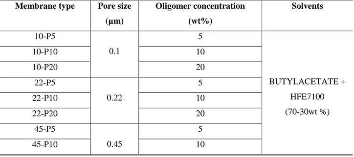
Innovative hydrophobic coated membranes have been prepared and characterised in Direct Contact Membrane Distillation (DCMD) for potential water treatment applications. A UV-curable perfluoropolyether (PFPE) hydrophobic compounds (Fluorolink® AD 1700 and Fluorolink® MD 700) were used as coating material to tailor the surface of commercial microfiltration hydrophilic polyamide (PA), and polyethersulfone (PES) membranes with different pore sizes (0.1-0.22-0.45µm). The coated membranes consisted of a top thin hydrophobic porous layer overlying the hydrophilic commercial membrane support. Produced membranes were fully characterised in terms of surface and cross-section morphology, water contact angle, porosity, pore size, mechanical test and liquid entry pressure. The innovative coated hydrophobic membranes were tested in DCMD configuration, using deionized water and salty solution 0.6 M (NaCl) as feed. In particular, the effect of the coating concentration, and the starting materials, on the permeate fluxes was investigated. The coating resistance was evaluated over time by direct contact with several chemical agents. The measured permeate fluxes ranged between 4.56-22.81 kg/m2 h at different feed temperatures (40-50-60°C) keeping constant the permeate temperature at 14°C, for deionized water, whereas an average value of 11 kg/m2 h, at 50°C was found in case of the salty solution.
13 Reference
[1] F.M. Kerton, Alternative Solvents for Green Chemistry, RSC Publishing, Cambridge UK, 2009. doi:10.1039/9781849736824.
[2] K.L.H. Intzer, T.I.Z. Ipplies, Fluoropolymers , Organic, (2013).
[3] S. Ebnesajjad, Introduction to Fluoropolymers, Elsevier, 2011. doi:10.1016/B978-1-4377-3514-7.10004-2.
[4] J. Gardiner, Fluoropolymers: Origin, Production, and Industrial and Commercial
Applications, Australian Journal of Chemistry. 68 (2015) 13–22. doi:10.1071/CH14165. [5] R.W. Baker, Membrane Technology and Applications, 2004. doi:10.1002/0470020393. [6] Z. Cui, E. Drioli, Y.M. Lee, Recent progress in fluoropolymers for membranes, Progress in
Polymer Science. 39 (2014). doi:10.1016/j.progpolymsci.2013.07.008.
[7] H. Strathmann, L. Giorno, E. Drioli, Basic Aspects in Polymeric Membrane Preparation, Comprehensive Membrane Science and Engineering Volume 1. (2010) 1570.
[8] I.M. Wienk, R.M. Boom, M.A.M. Beerlage, A.M.W. Bulte, C.A. Smolders, H. Strathmann, Recent advances in the formation of phase inversion membranes made from amorphous or semi-crystalline polymers, 113 (1996) 361–371.
[9] P. van de Witte, P.J.J. Dijkstra, J.W. a. W. a van den Berg, J. Feijen, Phase separation processes in polymer solutions in relation to membrane formation, Journal of Membrane Science. 117 (1996) 1–31. doi:10.1016/0376-7388(96)00088-9.
[10] M. Gu, J. Zhang, X. Wang, H. Tao, L. Ge, Formation of poly(vinylidene fluoride) (PVDF) membranes via thermally induced phase separation, Desalination. 192 (2006) 160–167. doi:10.1016/j.desal.2005.10.015.
[11] S. Simone, A. Figoli, S. Santoro, F. Galiano, S.M. Alfadul, O.A. Al-Harbi, E. Drioli,
Preparation and characterization of ECTFE solvent resistant membranes and their application in pervaporation of toluene/water mixtures, Separation and Purification Technology. 90 (2012) 147–161. doi:10.1016/j.seppur.2012.02.022.
[12] M. Gu, J. Zhang, X. Wang, W. Ma, Crystallization behavior of PVDF in PVDF-DMP system via thermally induced phase separation, Journal of Applied Polymer Science. 102 (2006)
14 3714–3719. doi:10.1002/app.24531.
[13] K. Alfonsi, J. Colberg, P.J. Dunn, T. Fevig, S. Jennings, T.A. Johnson, H.P. Kleine, C. Knight, M.A. Nagy, A. Perry, M. Stefaniak, Green chemistry tools to influence a medicinal chemistry and research chemistry based organisation {, Green Chemistry. 10 (2008) 31–36. doi:10.1039/b711717e.
[14] A. Figoli, T. Marino, S. Simone, E. Di Nicolò, X. Li, T. He, S. Tornaghi, Towards non-toxic solvents for membrane preparation : a review, Green Chemistry. 16 (2014) 4034–4059. doi:10.1039/c4gc00613e.
[15] H. Karkhanechi, S. Rajabzadeh, E. Di Nicolò, H. Usuda, A.R. Shaikh, H. Matsuyama, Preparation and characterization of ECTFE hollow fiber membranes via thermally induced phase separation (TIPS), Polymer. 97 (2016) 515–524. doi:10.1016/j.polymer.2016.05.067. [16] B. Zhou, Q. Li, Y. Tang, Y. Lin, X. Wang, Preparation of ECTFE membranes with
bicontinuous structure via TIPS method by a binary diluent, Desalination and Water Treatment. 57 (2016) 17646–17657. doi:10.1080/19443994.2015.1086898.
[17] C. Ursino, S. Simone, L. Donato, S. Santoro, M.P. De Santo, E. Drioli, E. Di Nicol?, A. Figoli, ECTFE membranes produced by non-toxic diluents for organic solvent filtration separation, RSC Advances. 6 (2016). doi:10.1039/c6ra13343f.
[18] E. Drioli, S. Santoro, S. Simone, G. Barbieri, A. Brunetti, F. Macedonio, A. Figoli, ECTFE membrane preparation for recovery of humidified gas streams using membrane condenser, REACTIVE AND FUNCTIONAL POLYMERS. 79 (2014) 1–7.
doi:10.1016/j.reactfunctpolym.2014.03.003.
[19] B. Zhou, Y.K. Lin, W.Z. Ma, Y.H. Tang, Y. Tian, X.L. Wang, Preparation of ethylene chlorotrifluoroethylene co-polymer membranes via thermally induced phase separation, Gaodeng Xuexiao Huaxue Xuebao/Chemical Journal of Chinese Universities. 33 (2012) 2585–2590. doi:10.7503/cjcu20120033.
[20] J.F. Kim, J.T. Jung, H.H. Wang, S.Y. Lee, T. Moore, A. Sanguineti, E. Drioli, Y.M. Lee, Microporous PVDF membranes via thermally induced phase separation (TIPS) and stretching methods, Journal of Membrane Science. 509 (2016) 94–104.
doi:10.1016/j.memsci.2016.02.050.
[21] J.T. Jung, J.F. Kim, H.H. Wang, E. di Nicolo, E. Drioli, Y.M. Lee, Understanding the non-solvent induced phase separation (NIPS) effect during the fabrication of microporous PVDF
15
membranes via thermally induced phase separation (TIPS), Journal of Membrane Science. 514 (2016) 250–263. doi:10.1016/j.memsci.2016.04.069.
[22] J. Lee, B. Park, J. Kim, S. Bin Park, Effect of PVP, lithium chloride, and glycerol additives on PVDF dual-layer hollow fiber membranes fabricated using simultaneous spinning of TIPS and NIPS, Macromolecular Research. 23 (2015) 291–299. doi:10.1007/s13233-015-3037-x. [23] S.-I. Sawada, C. Ursino, F. Galiano, S. Simone, E. Drioli, A. Figoli, Effect of citrate-based
non-toxic solvents on poly(vinylidene fluoride) membrane preparation via thermally induced phase separation, Journal of Membrane Science. 493 (2015).
doi:10.1016/j.memsci.2015.07.003.
[24] L. Wang, D. Huang, X. Wang, X. Meng, Y. Lv, X. Wang, R. Miao, Preparation of PVDF membranes via the low-temperature TIPS method with diluent mixtures: The role of coagulation conditions and cooling rate, Desalination. 361 (2015) 25–37.
doi:10.1016/j.desal.2015.01.039.
[25] Z. Cui, N.T. Hassankiadeh, S.Y. Lee, K.T. Woo, J.M. Lee, A. Sanguineti, V. Arcella, Y.M. Lee, E. Drioli, Tailoring novel fibrillar morphologies in poly(vinylidene fluoride) membranes using a low toxic triethylene glycol diacetate (TEGDA) diluent, Journal of Membrane
Science. 473 (2015) 128–136. doi:10.1016/j.memsci.2014.09.019.
[26] L. Wu, J. Sun, Structure and properties of PVDF membrane with PES-C addition via thermally induced phase separation process, Applied Surface Science. 322 (2014) 101–110. doi:10.1016/j.apsusc.2014.10.083.
[27] N.T. Hassankiadeh, Z. Cui, J.H. Kim, D.W. Shin, A. Sanguineti, V. Arcella, Y.M. Lee, E. Drioli, PVDF hollow fiber membranes prepared from green diluent via thermally induced phase separation: Effect of PVDF molecular weight, Journal of Membrane Science. 471 (2014) 237–246. doi:10.1016/j.memsci.2014.07.060.
[28] Z. Cui, N.T. Hassankiadeh, S.Y. Lee, J.M. Lee, K.T. Woo, A. Sanguineti, V. Arcella, Y.M. Lee, E. Drioli, Poly(vinylidene fluoride) membrane preparation with an environmental diluent via thermally induced phase separation, Journal of Membrane Science. 444 (2013) 223–236. doi:10.1016/j.memsci.2013.05.031.
[29] Z.C. Zhang, C.G. Guo, X.M. Li, G.C. Liu, J.L. Lv, Effects of PVDF Crystallization on Polymer Gelation Behavior and Membrane Structure from PVDF/TEP System via Modified TIPS Process, Polymer-Plastics Technology and Engineering. 52 (2013) 564–570.
16 doi:10.1080/03602559.2012.762521.
[30] H.-Q. Liang, Q.-Y. Wu, L.-S. Wan, X.-J. Huang, Z.-K. Xu, Polar polymer membranes via thermally induced phase separation using a universal crystallizable diluent, Journal of Membrane Science. 446 (2013) 482–491. doi:10.1016/j.memsci.2013.07.008.
[31] M. Ulbricht, Advanced functional polymer membranes, Polymer. 47 (2006) 2217–2262. doi:10.1016/j.polymer.2006.01.084.
[32] Drioli E. and Giorno L., Membrane Operations Innovative Separations and Transformations, WILEY-VCH, 2009.
[33] S. Santoro, E. Drioli, A. Figoli, Development of Novel ECTFE Coated PP Composite Hollow-Fiber Membranes, Coatings. 6 (2016) 40–52. doi:10.3390/coatings6030040.
17
Chapter 1.
ECTFE membranes produced by non-toxic diluents for organic solvent filtration separation
1.1 Introduction
Organic solvents are usually employed in different production processes, such as chemicals production, pharmaceutical industries, petrochemical sector, cosmetic, purification and processing of food, nutraceuticals and natural products. Therefore, solvent recycling is one of the main issues of the chemical and pharmaceutical industries, in fact, industrial wastes may be toxic, corrosive or reactive, that can lead to environmental and human health consequences. The traditional practices of solvent recycling rely on pre-treatments (addition of additives), evaporation and distillation. However, these processes are costly, require high temperatures or use of other type of chemicals. With respect to these techniques, membranes allow the facile, safe and low-cost recovery, concentration or purification of the target molecules (non-thermal separation)[1]. In particular, ultrafiltration (UF) and nanofiltration (NF) pressure-driven membrane processes are of particular interest for the organic solvent separation. The first publications concerning their application were reported by Nguyen [2] for UF and Eriksson[3] for NF, respectively. Main examples of UF process include the fractionation and purification of peptide or impurities from protein solution [4]and the extraction polyphenols from seeds [5]. Organic solvent nanofiltration (OSN) has gained popularity as membrane process for different applications, such as purification of pharmaceutically active ingredients [6], specific recognition of genotoxins[7] recovery of catalyst in chemical synthesis [8], separation of ionic liquids [9], and solvent exchange [10]. Both UF and NF processes were used in pharmaceutical and biotechnological applications to extract, isolated and concentrated compounds of interest [5,11–14]from organic solvent media. For both types of membranes it is of primary importance the membranes stability in the presence of harsh solvents.
New generation of NF membranes is more stable towards organic solvents, but full-scale applications are still limited, because of the low number of available commercial solvent-resistant membranes. Nowadays, the typical polymers used for preparing NF membranes are Polyimide (PI) including co-Polyimidies (co-PIs), Polydimethylsiloxane (PDMS), Polyacrilonitrile (PAN) [15], Polyamide (PA) [16], Polysulfone (PS) [17]. Table 1 reports examples of typical polymers used in UF and NF membranes preparation and applications.
18
*Chapter based on the manuscript : C. Ursino, S. Simone, L. Donato, S. Santoro, M. P. De Santo, E. Drioli, E. Di Nicolò, A. Figoli “ECTFE membranes produced by non-toxic diluents for organic solvent filtration separation, RSC Adv., 6 (2016), 81001-81012, DOI:10.1039/C6RA13343F
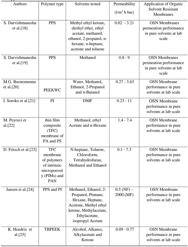
Table 1. Examples of typical polymers used in organic solvent UF and NF membranes preparation and applications
Authors Polymer type Solvents tested Permeability (l/m2 h bar) Application of Organic Solvent Resistant Membranes S. Darvishmanesha et al.[18]
PPS Methyl ethyl ketone, diethyl ether, ethyl
acetate, methanol, ethanol, 2-propanol,
n-hexane, n-heptane, acetone and toluene
0.02 - 3.21 OSN Membranes permeation performance
in pure solvents at lab scale
S. Darvishmanesha et al.[19]
PPS Methanol 0.8 - 9 OSN Membranes
permeation performance in pure solvents at lab
scale M.G. Buonomenna et al.[20] PEEKWC Water, Methanol, Ethanol, 2-Propanol and n-Butanol 0.27 - 3.63 OSN Membrane performance in pure solvents at lab scale
I. Soroko et al.[21] PI DMF 0.23 - 11 OSN Membrane
performance in pure solvents at lab scale M. Peyravi et al.[22] thin film composite (TFC) membrane of PA and PS Methanol, ethyl Acetate and n-Hexane
1.4 - 7.4 OSN Membrane performance in pure solvents at lab scale
D. Fritsch et al.[23] TFC membrane of polymers of intrinsic microporosit y (PIMs) and PAN N-heptane, Toluene, Chloroform, Tetrahydrofuran, Methanol and Ethanol
0.1 - 7.3 OSN Membrane performance in pure solvents at lab scale
Jansen et al.[24] PPS and PI Methanol, Ethanol, 2-Propanol, Pentane,
Hexane, Heptane, Acetone, Methyl ethyl ketone, Methylacetate, Ethylacetate, isopropyl Acetate 0.5 (NF) – 2000 (MF) OSN Membrane performance in pure solvents at lab scale
K. Hendrix et al.[25]
TBPEEK Alcohol, Alkanes, Alkylacetate and
Ketone
0.09 - 0.77 OSN Membrane performance in pure solvents at lab scale
19 M. F. J. Solomon et al.[26] PI TFC THF, Toluene and ethyl Acetate 0. 3 - 3.83 OSN Membrane performance in pure solvents at lab scale L. Liu et al.[27] PASS Water, Ethanol,
Methanol, n-Butanol
0.5 – 1.24 OSN Membrane performance in pure solvents at lab scale F. M. Penha et al.[28] PES and Hydrophilic PES Water, Ethanol, 2-Propanol and n-Hexane 0.3 (NF) – 250.3 (UF) UF-NF Membrane performance in pure solvents at lab scale F. M. Penha et
al.[29]
PES and Hydrophilic
PES
Oil and Hexane 0.1 – 2.5 NF Permeation of oil/hexane mixture at lab
scale M. Saxena et
al.[30]
PS Hexane 79- 364 UF Membrane
performance in pure solvents at lab scale M. V. Tres et
al.[31]
PES/PVP Oil and Hexane 2 (NF) - 27.5 (UF)
UF-NF Separation of soybean oil/n-butane at
lab scale M. Eliza et al.[11] PAN-based Aqueous solutions of
Ethanol
0.45 - 2.34 NF Treatment of ethanol extracts of corn at lab
scale H. Nawaz et al.[5] Cellulose
acetate/cellul ose nitrate mixed esters Aqueous solutions of Ethanol - Extraction and concentration of polyphenols at lab scale *PDMS: Polydimethylsiloxane; PEEKWC: Polyetheretherkeetone; PI: Polyimide, TFC: Thin-film composite membrane; DMF: Di-methyl Formamide; THF: Tetrahydrofuran; NMP: N-methyl Pyrrolidone; PAN: Polyacrylonitrile; PPS: Polyphenylsulfone, PES: Polyethersulfone, PS: Polysulfone, PVP: Poly(vinylpyrrolidone), PASS: Polyarylene sulfide sulfone, PA: Polyamide.
The influence of the polymeric materials, in terms of separation performance, was well summarized in the paper of Cheng et al.[32]. Other authors showed that, beside the polymer type, also the selected solvent and eventual additives influence the performance of the solvent resistant nanofiltration (SRNF) membranes [33]. A suitable solvent-resistant materials, as Halar® ECTFE (Ethylene-Chlorotrifluoroethylene), a perfectly alternating copolymer of ethylene and chlorotrifluoroethylene, could be used in the chemical process industry due to its properties such as excellent chemical resistance and mechanical properties [34,35]. However, due to its chemical-physical stability, ECTFE is difficult to be processed with the conventional membrane manufacturing techniques. In fact, ECTFE membranes are usually prepared via thermally induced phase separation (TIPS) technique and the polymer is solubilized in organic solvents at high temperature. The patent of Mutoh and Miura
20
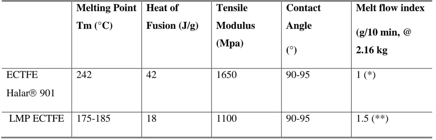
was the first one reporting successful TIPS casting of ECTFE [36]. Several studies were performed to identify high-boiling organic solvents able to dissolve ECTFE [37]. Among them, Tri-ethyl Citrate (CTF), Glycerol Triacetate (GTA) and Di-octyl Adipate (DOA) have been used in the ECTFE membrane formation thanks to their low toxicity in comparison than phthalates, such as Di-butyl Phthalate (DBP) or Di-ethyl Phathalate (DEP)[38–42]. However, in all these cases, the ECTFE polymer was solubilised at temperature over 180°C. Solvay Specialty Polymers has recently developed a lower melting point grade of Halar® ECTFE, named here LMP ECTFE, which still offers the above quoted outstanding chemical resistance in caustic environments. Moreover, it shows comparable properties with standard Halar® (hydrophobicity and mechanical properties), but lower crystallinity and lower melting point [43]. ECTFE Halar 901 and LMP ECTFE properties are summarized in Table 2. Molecular weight (MW) of ECTFE polymers cannot be directly determined by GPC. However, since the Melt Flow Index (MFI) can be provided and it is proportional to the molecular weight, information on their MW could be indirectly obtained [44]. For Halar 901, the Average Melt Flow Index (MFI) at 275 °C (527 °F), under a Load of 2.16 Kg, is 1 g/10 min; for LMP ECTFE, the MFI, at 225°C following ASTM D1238, is 1.5 g/10 min. On the basis of this parameter, it can be concluded that LMP ECTFE has lower MW and lower viscosity with respect to Halar 901. The same issue is related to the ethylene content, which is also not given by the supplier but it can be identified by other polymer properties. In fact, it is possible to obtain information on the Melting point and the Heat of fusion. For Halar 901 the Melting point is 242 °C, while the Heat of fusion is 42 J/g. For LMP ECTFE the Melting point is 175-185 °C, while the Heat of fusion is 18 J/g. These parameters are connected to the ethylene content. Since they are lower with respect to the standard Halar, in which the ethylene/cloro-trifluoroethylene ratio is 1:1; it could be concluded that, for LMP ECTFE, the ethylene content is less than 50 molar%.
Table 2. ECTFE Halar 901 and LMP ECTFE properties Melting Point Tm (°C) Heat of Fusion (J/g) Tensile Modulus (Mpa) Contact Angle (°)
Melt flow index (g/10 min, @ 2.16 kg ECTFE Halar 901 242 42 1650 90-95 1 (*) LMP ECTFE 175-185 18 1100 90-95 1.5 (**)
21
(*) At 275°C following ASTM D 1238 “Standard Test Method for Melt Flow Rates of thermoplastics by Extrusion Plastometer”.
(**) At 225°C following ASTM D1238.
In this work, LMP ECTFE flat-sheet membranes were prepared by means of TIPS. In this perspective, solvents with low toxicity were employed. In particular, the first part of this investigation focused on the study of different non-toxic solvents as possible diluents selected on the basis of their environmental impact, high boiling point and solubility towards the polymer used. Then, LMP ECTFE flat membranes were prepared and characterized in terms of morphology, contact angle, mechanical test, porosity and pore size. In particular, swelling tests in pure organic solvents as Methanol, Ethanol, 2-Propanol, Hexane, Cyclohexane, Tetrahydrofuran, Toluene, N-methyl Pyrrolidone, Di-methyl Acetamide , Di-methyl Formamide were carried out for evaluating the LMP ECTFE dense film resistance. Finally, organic solvent permeation tests on selected solvents were performed using the novel LMP ECTFE membranes produced.
1.2 Experimental 1.2.1 Materials
The ECTFE based polymers (experimental ECTFE Halar 901 and LMP ECTFE) were kindly supplied by Solvay Specialty Polymers and used without any further purification. Di-ethyl Adipate (DEA), Ethanol (EtOH), 2-Propanol (IPA), Methanol (MetOH), Acetone, Tetrahydrofuran (THF), Toluene (Tol), N-methyl Pyrrolidone (NMP), Di-ethylene Glycol (DEG), Di-butyl Itaconate (DBI), Glycerol, Chloroform, Di-methyl Acetamide (DMA), Di-methyl Formamide (DMF), Cyclohexane (C6H12), Hexane, Fluorinert® FC-40, Kerosene oil, were all purchased from Sigma–Aldrich and used without any further purification. Liquid nitrogen was purchased from Pirossigeno (Cosenza, Italy).
1.2.2 LMP ECTFE solubility tests
The solubility tests were carried out using different types of solvents: DBI and DEA. Their chemical structure is reported in Figure 1.
Figure 1. Chemical structure of solvents of interest
DMSO GBL NMP
CTF GTA
22
Solvents were selected on the basis of their high boiling point, solubility parameters, lower toxicity and environmental impact, compared with the phthalates, 1,3,5-Trichlorobenzene (TCB), Di-butyl Phthalate (DBP) and Di-octyl Phthalate (DOP)[36], which are the solvents usually used for the preparation of ECTFE-based membrane by TIPS (Table 3). Similar solubility parameters indicate good affinity between solvent and polymer. In this case would be expected the completely dissolution of the polymer, whilst those with dissimilar values would not.
Table 3. Solvents properties Solvent Molecular Formula Molar Mass (g mol-1) Density (g cm-3) Boiling point (°C)
δd (MPa)1/2 δp (MPa)1/2 δh (MPa)1/2
DEA C10H18O4 202 1.01 251 16.4 6.2 7.5
DBI C13H22O4 242 0.98 284 16.9 10 22
ECTFE Halar 901 16.8 8.4 7.8
δd δp and δh, are the solubility parameters related to, dispersion parameters, polar forces and hydrogen bonding, respectively
Solubility tests were carried out heating and magnetically stirring (50 rpm) the polymeric solution (15wt% LMP ECTFE – 85wt% solvent) in an oil bath. The polymer solubilisation was evaluated by increasing the temperature of 10°C each 30min, from room to a maximum temperature value, close to the boiling point of the solvent employed.
In particular, an homogeneous solution (15wt% LMP ECTFE/ 85wt% solvent) was observed at 140°C for DEA and 170°C for DBI. The possibility of decreasing drastically the temperature of polymer solution makes easier the polymer processability. Based on these results and considering also the low toxicity, DEA was selected as solvent for the preparation of LMP ECTFE flat sheet membranes.
1.2.3 Polymeric dope solution preparation
Polymeric dopes were prepared by dissolving the polymer in DEA at different concentrations (15-20-25% w/w). Each solution was stirred for 1h at temperature of 193°C until complete dissolution of the components was achieved. The polymeric dope was allowed to degas, keeping the temperature, for 6h before casting.
23
1.2.4 Preparation of LMP ECTFE membranes and dense films
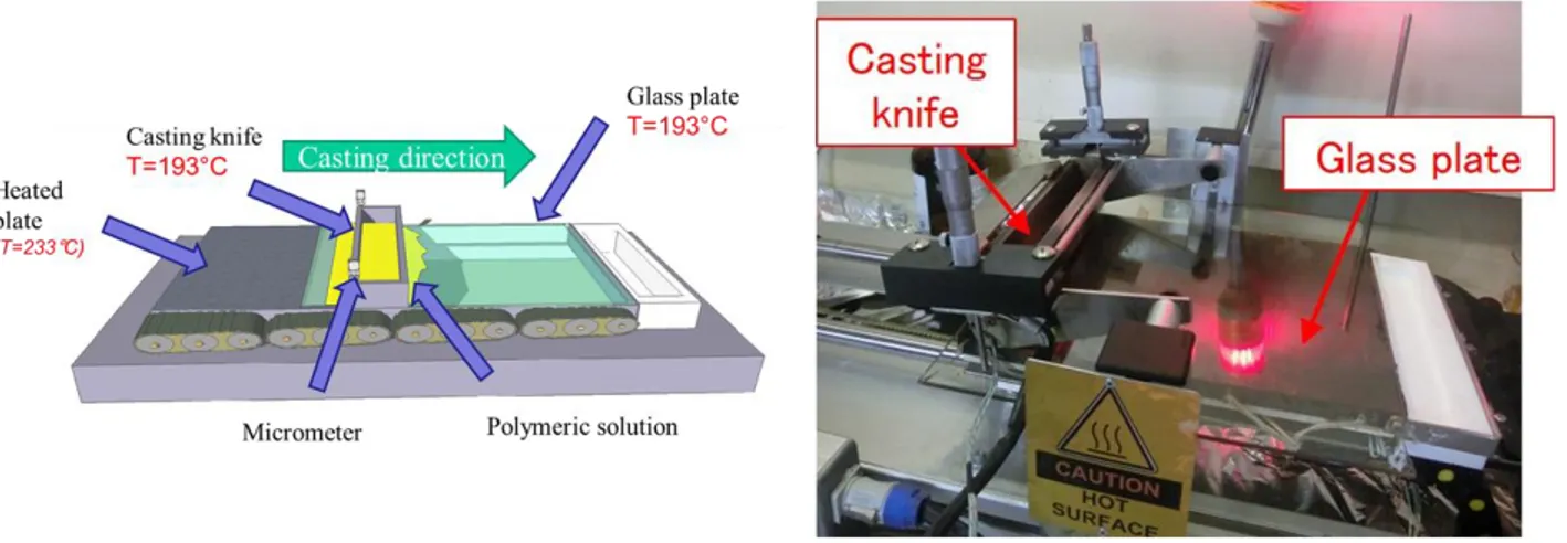
Membranes were prepared by casting the polymeric solution over a suitable smooth glass support by means of an automatized casting knife (DeltaE srl, Italy) Figure 2.
Figure 2. Automatized casting knife.
The dope solution, having a polymer concentration in the range of 15-25 wt.%, was cast by keeping both the casting knife and the support to the temperature of 193°C, to prevent premature precipitation of the polymer.
After casting and evaporation, polymeric membranes were cooled down by immersing them in the coagulation bath of pure Di-ethylene Glycol (DEG) at 5°C. This value of temperature, among the others used (25°C and 60°C), has been found optimal for the preparation of reproducible polymeric porous membranes. After coagulation, the membranes were washed overnight in 2-Propanol. In case of preparation of dense film, specifically made for evaluating the solvent resistant of the LMP ECTFE, no coagulation bath was used and the cast dope solutions were cool down overnight slowly. In the dense film (D), DEA was extract by washing in ethanol (typical step in a TIPS process), three times and drying in an oven for 6 h.
All the membrane conditions are resumed in Table 4.
Table 4. Summary of the main preparation conditions for LMP ECTFE membranes Membrane type Polymer conc. (wt%) Casting knife (µm) Air exposure time (sec) Coagulation bath type Coagulation bath Temperature (°C) Drying procedure L2 15 300 0
24 M2 20 300 0 DEG 5 isopropanol over night and after drying at air N2 25 300 0 Dense Film (D)
20 250 over night - - direct drying
1.2.5 Determination of the binary phase diagram
ECTFE Halar® 901 and LMP ECTFE solubility in DEA was evaluated by monitoring the cloud point (CP) of solutions containing different weight percentages of polymer. In each case, the polymer was added to the solvent at room temperature and solubilised by magnetically stirring the solution (50 rpm) increasing the temperature by using the oil bath. Once the polymeric solution was completely solubilised, the dope solution was cooled (rate of cooling was 0.1°C min-1) until the cloud point (Solid-Liquid Demixing) occurred. The tests were performed varying the polymer concentration from 5wt% to 35wt%.
1.3 Membrane characterization
1.3.1 Scanning electron microscopy (SEM)
Membranes morphology (cross section, top and bottom side) was observed by using a scanning electron microscope (Zeiss EVO MA 100, Assing, Italy). The sample for the evaluation of the membrane cross-section was fractured in liquid nitrogen. Samples were sputter-coated with a thin gold film prior to SEM observation.
1.3.2 Atomic force microscopy (AFM)
Atomic force microscopy was used to study the top and bottom surface morphology and roughness of the prepared membranes. The AFM device was a Bruker Multimode 8 with Nanoscope V controller. Data were acquired in tapping mode, using silicon cantilevers (model TAP150, Bruker). The membrane surfaces were imaged in a scan size of 10 µm x 10 µm.
1.3.3 Contact angle measurements
Contact angle measurements were performed with ultrapure water using the sessile drop method by a CAM100 instrument. For all membranes, at least five measurements were taken both on the air and the glass sides; the average values and the corresponding standard deviation were then calculated.
25 1.3.4 Swelling tests
According to Standard Practices for Evaluating the Resistance of Plastics to Chemical Reagents [45], to measure the swelling degree, dense film samples (A= 4cm2) were weighted and placed in suitable solvent resistant containers. The quantity of reagent shall be approximately 12.5 mL/cm2 of specimen surface area. Samples were kept totally immersed, for 72h-120h-172h at standard laboratory atmosphere (25°C), in one of the following pure organic solvents: EtOH, MetOH, Acetone, THF, Tol, NMP, EtOAc, DMA and DMF. The swelling degree (Sw) was calculated as follows:
Sw= (𝑊𝑊−𝑊𝐷
𝑊𝐷 )* 100%
Where WW is the weight of the dense film after 72h-96h-172h of immersion and WD is the initial weight of the dry dense film.
1.3.5 Mechanical tests
The Young’s or elastic modulus (Emod), the tensile stress at break (Rm) and breaking elongation or stress at break (eBreak) were measured by means of a ZWICK/ROELL Z 2.5 test unit. Each sample was stretched unidirectionally at a constant rate of 5 mm/min; the initial distance between the clamps was of 50 mm. Five specimens were tested for each sample.
1.3.6 Porosity
Membrane porosity (Ɛm) was determined according to the gravimetric method, described in literature47. Porosity was defined as the ratio between the volume of the membrane and the volume of voids present within it. Dry membrane pieces were weighted and impregnated in kerosene for 24h; after this time, the excess of liquid was removed with tissue paper, and membranes weight was measured again. Finally, porosity was calculated applying the following formula:
Ɛ(%) = ( 𝑊𝑤−WD ρK ) ((𝑊𝑤−WD) ρK +( WD ρP)) ∗ 100
Where WW is the weight of the wet membrane, WD is the weight of the dry membrane, ρK is the kerosene density (0.82 g/cm3) and ρP is the polymer density (1.71 g/cm3). For all membranes types, three measurements were performed; then, the average values and corresponding standard deviation were calculated.
26
Membrane bubble points, largest pore size and pore size distribution were determined using a PMI Capillary Flow Porometer (CFP1500 AEXL, Porous Materials Inc., USA). For each test, membranes samples were initially fully wetted using Fluorinert FC-40 (16 dyne/cm), for 24h and placed in the sample holder. Bubble point, gas pressure and flow rates through the dry membranes were measured. This operating mode, named wet-up/dry-up, was selected using the software Capwin. The measurement of bubble point, largest pore size and pore size distribution is based on the Laplace’s equation:
dP = 4 τ cosθ 𝑃
where dP is the pore diameter, τ is the surface tension of the liquid, θ is the contact angle of the liquid (assumed to be 0 in case of full wetting, which means cosθ = 1) and P is the external pressure. The results of each test were exported as an excel file using the software Caprep for further processing.
1.3.8 Solvent Filtration experiments
Filtration tests were performed in a high pressure crossflow filtration cell (model HP4750) supplied from Sterlitech corporation (USA). The volume was 300 mL and the diameter 5.1 cm. The effective membrane area was 20.4 cm2.
Experiments were performed using the solvents at room temperature, as indicated in Table 5.
Table 5. Characteristics of the organic solvents used in the filtration experiments [46] Solvent Molecular Weight (g/mol) Density (g/mL) Surface tension ϒ (mN/m) Viscosity (cP) Polarity
Methanol 32.04 0.791 22.1 0.60 Protic polar
Ethanol 46.10 0.789 21.9 1.20 Protic polar
DMF 73.09 0.944 37.1 0.82 Aprotic polar
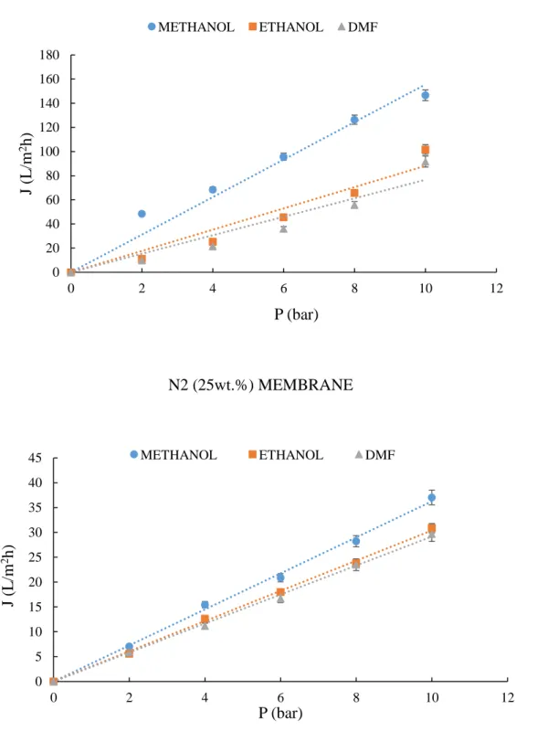
The cell was filled with one of the following solvents: Methanol, Ethanol, and DMF. Before the tests, each membrane was conditioned by immersing in the target pure solvent for 24 h, and then placed in the cell. Experiments were carried out by applying different N2 gas pressures (trans-membrane pressure (TMP)) from 2 to 10 bar. The permeate was collected at atmospheric pressure. Each membrane filtration test was conducted three times. Solvent flux (J) through each membrane, at a
27
given pressure, was defined as the volume permeated per unit area and per unit time. J was calculated by the following equation:
J = 𝑉 (A Δt)
where V (L) is the volume of permeate, A (m2) is the membrane area, and Δt (h) is the operation time. The average and relative standard deviation were calculated.
From the slope of the J vs. P linear relationship, the membrane permeability was calculated according to a least-square fitting method.
1.4 Results and discussion
1.4.1 Determination of the binary phase diagram
The cloud point (CP) of LMP ECTFE/DEA and ECTFE Halar 901 system, as a function of polymer concentration, was determined. The initial thermodynamically stable homogeneous solution, made of polymer and solvent, separates into two phases decreasing the temperature. The polymer-rich phase forms the membrane structure, and the polymer-lean phase forms the pores [47]. The binary phase diagram indicates the miscibility gap of the solution, at different polymer concentration. In general, the CP of a polymer/solvent system depends on its stability, which in turn is influenced by the solubility of the polymer in the same solvent. This depends on the Hansen’s solubility parameters, but also on the polymer degree of crystallinity. Since, usually, a crystalline polymer is more stable, the interactions between the chains are stronger and, therefore, it is more difficult to dissolve. As reported in Figure 3, LMP ECTFE CP was lower that the ECTFE Halar 901. In this case, the two polymers’ solubility parameters are very close. However, LMP ECTFE is easier to dissolve because of its lower crystallinity (Table 2) and therefore, the compatibility of polymer/solvent is higher for LMP ECTFE/DEA. Moreover, it was observed that the CP increased at higher polymer concentration. Phase separation mechanism usually influences the membrane morphology. In fact, the liquid-liquid (L/L) demixing is favoured at low temperature and low polymer concentration, leading to cellular morphologies, while solid-liquid (S/L) demixing generally occurred at high polymer concentration and high temperature and brings to the formation of spherulites and axialites structures[47]. In particular, both our systems, LMP ECTFE/DEA and ECTFE Halar 901/DEA, did not become cloudy, until they began to form gels at the sol–gel transition temperature. Similar results were observed for PVDF/Citroflex system reported by Sawada et al.[48]. This result is in agreement with TIPS processes, where the higher temperature is necessary to keep the polymer/solvent system
![Table 5. Characteristics of the organic solvents used in the filtration experiments [46] Solvent Molecular Weight (g/mol) Density (g/mL) Surface tension ϒ (mN/m) Viscosity (cP) Polarity](https://thumb-eu.123doks.com/thumbv2/123dokorg/2868473.9196/36.892.70.827.767.981/characteristics-filtration-experiments-molecular-density-surface-viscosity-polarity.webp)