3 – An outline of MPLS technologies
3.1 – Overview
In this chapter the main characteristics of the MPLS architecture will be described, taking in particular consideration RFC 3031, in which the MPLS architecture has been standardized. This chapter is fundamental to have an idea of how MPLS functions.
3.2 – IP forwarding and Forwarding Equivalence Class
A packet in a connectionless network, like Internet, travels from a router to the following one and each router makes an independent forwarding decision for that packet. This means that every router analyzes the packet header and supports a network layer routing algorithm. Every router independently chooses the next hop for the packet, basing the decision on its analysis of the packet's header and the results of running the routing algorithm; but the IP header contains more information than is needed to simply choose the next hop for the packet, so, if the objective is only the forwarding, there is a considerable amount of data unused [RFC 3031].
The next hop choice is a composition of two functions:
• Dividing the packets into a set of “Forwarding Equivalence Classes” (FECs).
• Mapping each FEC to a next hop.
The assignment of a packet to a FEC is based on the Destination IP address. As regards the forwarding decisions, the packets mapped into the same FEC are indistinguishable. All packets belonging to a particular FEC and travelling from a particular node will follow the
same path. When a packet traverses the network, each hop in turn re-examines the packet and assigns it to a FEC [RFC 3031].
3.3 – MPLS forwarding
The meaning of the acronym MPLS is "MultiProtocol Label Switching", multiprotocol because its techniques are applicable to all the protocols of the Network Layer, even if its optimal use is with the IP protocol, and to quite all the protocols of the Data Link Layer. A router that supports MPLS is called a "Label Switching Router" (LSR).
MPLS is a backbone technology, this means that it is used particularly in the network core (as it is used in this thesis) and it is not employed in the client link [Davie, 00].
In MPLS, the assignment of a particular packet to a particular FEC is done just one time, when the packet enters the network. The FEC to which the packet is assigned is encoded in a short label with a fixed length. When a packet is forwarded to its next- hop, its label is forwarded too; so, the packets must be labeled before their forwarding [RFC 3031].
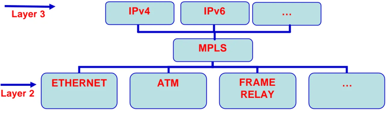
In the subsequent networks, there is no analysis (with the exception of some peculiar required cases) of the network header. The subsequent forwarding is based only on the label value. So, the forwarding operates on a sort of layer 2.5 as shown in figure 3.1.
Figure 3.1 – MPLS layer 2.5
MPLS
ETHERNET ATM FRAME
RELAY
…
IPv4 IPv6 …
Layer 3
With the label switching, MPLS operates a sort of network transformation from connection- less to connection-oriented. In fact, MPLS has the ability to create end-to-end circuits similar to the virtual circuits in ATM.
The forwarding mechanism at the MPLS basis can be divided into four fundamental steps:
• Classification: to identify the packet’s traffic flow.
• Label Assignment: assignment of a label or a label stack to a packet.
• Forwarding: based only on the label value.
• Label Removal: this happens at the MPLS domain exit. The use of the label switching technology brings a lot of advantages:
• All the complexity is le ft to the border routers (Label Edge Routers), keeping the network core simple.
• The possibility to get out of using the destination-base forwarding. Since a packet is assigned to a FEC when it enters the network, the ingress router can use, in order to determine the label assignment, all the information that it has about the packet. For example, different FECs can be assigned to packets arriving on different interfaces.
• The cons iderations that determine how a packet is assigned to a FEC can become as complicated as we want, without any impact at all on the routers that merely forward labelled packets. The entry router can use, to determine the assignment, any information that it has about the packet.
• Higher speed in the router forwarding, that can be managed by a sort of layer three switches, because there is no overhead to lookup to the network header.
• The possibility to force the traffic to follow an explicit path underloaded to exploit in a better way network resources [RFC 3031] [Tofoni, 03].
The analysis of the network layer header may be done not only with the objective to choose the packet's next hop, but also to determine a packet's precedence or class of service. Routers may then apply different discard thresholds or scheduling disciplines to treat the packets in different ways. MPLS allows the precedence or class of service to be fully or partially inferred from the label. In this case, in a certain sense the label represents the combination of a FEC and a precedence or class of service [RFC 3031].
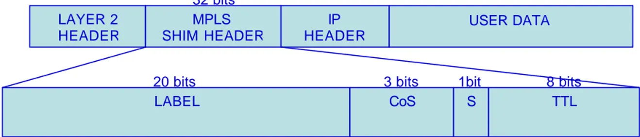
3.4 – Labels
A label is a short, fixed length, locally significant identifier which is used to identify a FEC [RFC 3031]. There are two possible options to codify a label into a packet:
• Using a dedicated short header called “shim” header, as shown in figure 3.2. The shim header is inserted between the data link and the network header. It is composed of 32 bits: 20 bits representing the effective label field; 3 bits Class of Service, used to better support the Differentiated Service; 8 bits Time To Live, analogous to the IP TTL; 1 bit Label Stack Indicator [RFC 3032].
Figure 3.2 – Shim header over IP
• Using the data link header if there is a field available to that purpose. This is the case of IP over ATM, where the VPI and VCI fields are used (figure 3.3).
Figure 3.3 – MPLS over ATM
LAYER 2 HEADER MPLS SHIM HEADER IP HEADER USER DATA LABEL CoS S TTL
20 bits 3 bits 1bit 8 bits
32 bits GF VP PT MPLS VC CL HE DAT
3.4.1 – Label Assignment
Before speaking about the label assignment, it is important to introduce the concepts of downstream and upstream routers: saying that a router is upstream and another is downstream means that a particular label represents a particular FEC for the packets travelling from the upstream to the downstream (figure 3.4).
Figure 3.4 – Label assignment, unsolicited downstream
The decision to assign a particular label L to a particular FEC is taken by the LSR that results downstream as regard that assignment, so the label is downstream assigned (figure 3.4, LSR2 assigns the label following the opposite direction to the data flow). The MPLS architecture allows two main ways to distribute the label assignments:
• An LSR distributes bindings to LSRs that have not explicitly requested them. This is known as "unsolicited downstream" label distribution, it is the way shown in figure 3.4.
• An LSR can explicitly request, from its next hop for a particular FEC, a label binding for that FEC. This is known as "downstream-on-demand" label distribution, this is the way shown in figure 3.5.
Figure 3.5 – Downstream on demand
Data Flow
LSR1
LSR2
Upstream Downstream Label Assignment Data FlowLSR1
LSR2
Upstream Label Assignation Request
Both these techniques of distribution can be used in the same network at the same time, but the LSRs have to agree on what technique will be used [RFC 3031].
3.4.2 – Label Stack
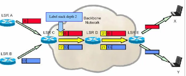
A labeled packet can carry a number of labels, organized as a last- in first-out stack, called “Label Stack”.
Although MPLS supports a hierarchy, the processing of a labelled packet is completely independent of the level of hierarchy. The processing is always based on the top label, without regard for the possibility that some number of other labels may have been "above it" in the past, or that some number of other labels may be below it at present [RFC 3031]. For example, looking at figure 3.6, in the Backbone Network we have a label stack with two labels, but the processing is based always on the top labels, that are 17 and 21.
Figure 3.6 – MPLS label stack
A packet without label can be thought as a packet whose label stack is empty (whose label stack has depth 0). If the label stack of a packet is of depth m, we refer to the label at the bottom of the stack as the level 1 label (labels 6 and 13 in figure 3.6), to the label above it (if exists) as the level 2 label (label 17 and 21 in figure 3.6), and to the label at the top of the stack as the level m label. The label stack is very useful in the cases of LSP Tunnel and MPLS Hierarchy [RFC 3031].
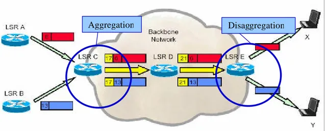
3.4.3 – Label Aggregation
The MPLS architecture allows the aggregation, which consists in the procedure of binding a single label to a union of FECs, which is itself a FEC. It is useful in the case in which a set of separate addresses has the same exit router. For example in figure 3.7 we can see that there are two flows directed respectively to X and Y, as they have the same exit router, that is the LSR E, they are aggregated in a single label (17 at the ingress LSR, and 21 at the second LSR), till the aggregated flow reaches the LSR E where it is disaggregated once again into two flows. This characteristic has a fundamental importance, because it allows reducing considerably the total amount of labels used into the network, the amount of the label distribution control traffic, and the memory use in the routers [Tofoni, 03].
Figure 3.7 – Flow aggregation and disaggregation
The aggregation has been used a lot in the different simulations in this thesis. For this reason, to clarify the employment of this characteristic in this work we remit the reader to chapter 5, and in particular to section 5.3.
3.4.4 – Label Switching (NHLFE, ILM, FTN)
In order to introduce the label switching (also called label swapping) it is better to speak before about the NHLFE, ILM and FTN.
The Next Hop Label Forwarding Entry (NHLFE) is a set of instructions for the forwarding of the packet to the subsequent router. More in detail, it contains:
• The next- hop of the packet
• The operation to do on the label stack of the packet, that will be one of the following operations:
o Replace the label at the top of the label stack with a specific new label o Extract from the battery of labels
o Replace the label at the top of the label stack with a specific new label and then insert in the label stack one or more labels.
o The data link encapsulation to use when the packet is transmitted o The way of codifying the label stack when the packet is transmitted o Some other information necessary for a correct managing of the packet The Incoming Label Map (ILM ) maps every entry label in a set of NHLFEs. It is used in the forwarding of labelled packets.
The "FEC-to-NHLFE" (FTN) maps every FEC in a set of NHLFEs. It is used in the forwarding of the unlabelled packets, but that will be labelled before the forwarding [RFC 3031].
3.4.5 – Label Switching
The label switching consists in a set of procedures to forward a packet:
1. An unlabelled packet is received at the Ingress LSR (that is a Label Edge Router), and the LER analyzes the Network Layer Header in order to establish the FEC. It
then uses the FTN to map this to an NHLFE. Using the information in the NHLFE, it determines where to forward the packet, and assigns a label to the packet (or performs an operation on the packet's label stack, if the LER is an edge router confining with another MPLS domain so that the packet received is labelled, situation shown in figures 3.6 and 3.7). This is the operation done by the first router in figure 3.8, where we have an ingress packet with IP address 192.4.2.1 and it is labelled with the label 5 and forwarded towards the subsequent LSR.
Figure 3.8 – Label switched path
2. The subsequent LSR receives the labelled packet, in order to forward it, the LSR examines the label at the top of the label stack (it is important to remember that also a packet with only one label is considered having a label stack with the depth of one). It uses in this case the ILM to map this label to an NHLFE. Using the information in the NHLFE, it determines where to forward the packet, and performs an operation on the packet's label stack. It then encodes the new label stack into the packet, and forwards the result. The situation is shown in figure 3.8 where the second LSR receives a packet with label 5 and, after popping that label, it forwards the packet with the new label 9. Obviously the situation now explained is the same for all the LSR operating in the same hierarchy level, for example the third router in figure 3.8 operates in the same manner than the second router. 3. When the packet arrives at the last LSR, looking at the label, it is noticed that it is
the penultimate hop popping, that is: the penultimate LSR forwards the packets as shown in the previous point 2, but the label is removed before the forwarding, so that the last LSR directly operates using the IP routing. The penultimate hop popping is useful because it permits to the last LSR to avoid the operation of looking at the last label.
It is important to notice that when the Label Switching is in use, the next-hop is always taken by the NHLFE; in some cases the next-hop can be different from the one that should be if MPLS was not used [RFC 3031].
3.5 – Label Switched Path (LSP)
A Label Switched Path (LSP) is a routing path in an MPLS network that starts from an entry LSR (ingress LSR) and ends in an exit LSR (egress LSR).
The ingress LSR inserts a label in the label stack of the packet resulting in a label stack with depth m. In figure 3.9 are shown two LSP with a label stack with depth 1.
The forwarding alo ng the LSP is based always on the label at the level m (that is the label on the top), and the LSP ends with an egress LSR when a forwarding decision is done by the label switching analyzing a level m-k label, where k>0, or when a decision on the forwarding is taken “ordinarily” not following MPLS procedures (like in figure 3.9). Looking at figure 3.6 or 3.7 there is an interesting case of an LSP with a label stack of depth 2 that starts from LSR C and ends at LSR E (where the forwarding is based on level 1), this case is interesting also because it shows that many characteristics can be associated to an LSP. In that case it uses an aggregation of two flows, but in more complicated cases (like those used in this thesis and explained in chapter 5) class of service and \or bandwidth assignment can be associated to an LSP.
Never during the transit of a packet through an LSP can its label stack have a depth minor than m.
Every time an LSR inserts a label in a packet already labelled, it has to make sure that the new label corresponds to a FEC whose egress LSR is the one that has assigned the label that now is second in the stack [RFC 3031].
4
Label switched paths
MPLS Domain LER LER LER LSR LSR LSR 34 9 23 192.6.3.1 192.6.3.1 192.6.3.1 192.6.4.3 56 4
Label switched paths
MPLS Domain LER LER LER LSR LSR LSR 34 34 9 9 23 23 192.6.3.1 192.6.3.1 192.6.3.1 192.6.4.3 56 56 Figure 3.9 – 2 LSPs
3.5.1 - LSP Control: Independent versus Ordered
The LSP setup can be done in two ways:• Independent LSP Control. Every LSR that recognizes a particular FEC makes an independent decision to assign a label to that FEC, and then it distributes that assignment to the other routers. It corresponds to the way in which the conventional IP routing works; every LSR makes an independent decision about how to treat every packet, it uses the routing algorithm to reach a rapid
An example of independent control is shown in figure 3.10 (where the downstream-on-demand is used for the label distribution), the second LSR has the possibility to answer immediately to the request made by the first router of a binding label-FEC.
Figure 3.10 – Independent control
Ordered LSP Control. In the Ordered LSP Control, an LSR assigns a label to a
particular FEC if it is the egress LSR for that FEC, or if it has already received a label binding for that FEC from its next hop for that FEC. The ordered control is useful if we want to assure that the traffic in a particular FEC follows a path with some specified set of properties (for example, that the traffic does not traverse any node twice, that a specified amount of resources are available to the traffic, that the traffic follows an explicitly specified path, etc.) [RFC 3031].
In figure 3.11 is shown an example of ordered control (also here the downstream-on-demand is used for the label distribution), in this case only the third LSR, that is the egress LSR for the FEC, can distribute the label binding.
Figure 3.11 – Ordered control Ingress Upstream Egress Downstream 1 -Label Request 2 -Label Assign Ingress Upstream 1 -Label Request 4 -Label Assign 2 -Label Request 3 -Label Assign Egress Downstream
3.6 - Route Selection and Explicit Routing
Route Selection refers to the method used to select the LSP for a particular FEC. An MPLS network can use two different ways for the route selection:
• Hop by Hop routing
• Explicit Routing
The Hop by Hop routing is the routing normally used in an IP network. In particular, using the Hop by Hop routing, each node can establish the next hop for a FEC.
In the Explicit Routing the LSP is explicitly selected. The selection is made by a single LSR (usually the ingress LSR or the egress LSR). The path can be selected only partially or the entire path can be selected [RFC 3031].
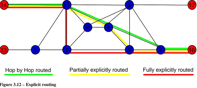
In figure 3.12 the green LSP is set by the normal routing (based on the distance vector algorithm), the yellow LSP is partially selected (because it is supposed that till the LSR 8 it follows the normal routing) adding another LSR to the shortest path, the red LSP is entirely selected.
Figure 3.12 – Explicit routing
The use of the MPLS architecture permits to employ the explicit routing running under the IP protocol. The Explicit Routing is fundamental in order to speak about the Traffic Engineering, which will be the argument of the next chapter.
11 7 10 2 5 8 4 1 14 13 16 17 11 7 10 2 5 8 4 1 14 13 16 17
3.7 – Label Distribution Protocol (LDP)
The Label Distribution Protocol (LDP), as its name suggests, is the protocol used to distribute and maintain the label bindings. It was developed by the IETF in RFC 3036 “LDP Specification”. Label distribution information needs to be transmitted reliably, and the label distribution protocol messages pertaining to a particular FEC need to be transmitted in sequence, if we want MPLS to work in a correct way [RFC 3036].
The main LDP characteristics are [Tofoni, 03] [Davie, 00]:
• The Discovery mechanism that allows the LDP peer automatic discovery.
• The Reliability, obtained using the TCP protocol.
• The Extendibility, using in the messages object codified using the Type Length Value coding.
The MPLS does not specify what protocol should be used for the label binding distribution. A lot of protocols can be used in substitution of LDP : Constraint-based Routed-Label Distribution Protocol (CR-LDP), RSVP and BGP. The choice of one of these protocols should be made on the basis of what is requested by the network. The LDP has been created only to be used in MPLS, but LDP cannot satisfy the necessities of QoS. To support QoS, it is possible to use an existing protocol for the resource reservation, extend ing it for the label distribution; or, another option is to take a protocol used for the label distribution, extending its capacity to support also the resource reservation. An example of a protocol of the first type that already supports both these types of reservations is the resource reservation protocol (RSVP). An example of a protocol of the second type is CR-LDP, an extension of the LDP protocol that will be treated deeply in the next chapter.