Simona Silvestri 85
Chapter 5
Different types of injectors
5.1 Introduction
The most critical part of a rocket engine combustor is the injector. It has always been recognized as a key component that often controls the success or failure of the combustion device. Any change in engine operating conditions or flow paths in the feed line and combustion chamber may lead to a drastically different injector behaviour.
When rocketry was in its infancy, injector designs were developed mainly through a time– consuming and costly process of trial and error [43]. The procedure was to copy previously successful designs, but soon it was understood that a proper scaling and control of the combustion process was necessary to have success; in fact a design that works well for one application may fail in another because of a subtle difference in operational requirements or system constraints. Analytical tools are now available or are being developed to evaluate these critical combustion processes so that candidate designs can be evaluated and optimized conceptually, thus avoiding or minimizing detailed design, manufacturing, and test cycles historically required. Even when the models are not completely understood it is possible to conduct lower cost experiments in a smaller scale to validate the assumptions.
In the following work different types of injectors and their general characteristics will be considered. Specifically, like impingement jet injector, the swirl injector and showerhead that have been considered for use in hybrid rockets will be examined.
5.2 Design objectives
For a given propellant combination, the chemical reaction and the kinetics of stream break-up, mixing, droplet formation, and heat transfer should be studied and clearly understood, before the approach to the design of an injector is established. The most important objectives for injector design are [44]:
- Combustion stability.
An injector should give smooth combustion, during engine start and stop transients as well as during steady-state operation. Depending upon the propellants and their characteristics, the arrival sequence of oxidizer and fuel streams during start is of great importance. Any accumulation of unburned propellants in the combustion chamber prior to ignition must be prevented to avoid destructive chamber-pressure surges. To prevent chamber-pressure fluctuations from affecting the propellant flows and thus from inducing combustion instability, sufficient pressure drop through injector orifice must be maintained. To suppress flow instabilities, the acoustic conductivity of an injector should be minimized, with the smallest possible response to disturbances arising from variations of the flow rate and other parameters. Then to suppress combustion instability and to achieve staged combustion, injectors should achieve prescribed distributions of atomization dispersivity, mixture ratio and flow intensity in the mixture-formation zone. For gas injectors, provisions should be made to remove acoustic energy from the chamber.
- Performance.
Combustion performance of an injector is influenced by: propellant mass distribution, local mixture ratio, degree of mixing of injected propellants, droplet atomization and vaporization, rate of heat input and chemical reaction rates. These are a function of suitable manifolding and proper selection of injector-hole patterns. Experience has shown that for a given injection velocity, propellant droplet size is reduced with decreasing injector-orifice size. Smaller droplet size, in turn, results in a higher overall vaporization rate, as a function of increased total droplet surface area. This is true whether the heat of vaporization is supplied internally via liquid phase reaction or externally by heat transfer from the hot gaseous combustion products.
Simona Silvestri 87
- Structural integrity.
An injector should be able to withstand the maximum loads incurred during all phases of engine operation. Sufficient cooling provisions prevent the injector face from overheating. The injector is highly loaded by pressure forces from the combustion chamber and the propellants manifold. During transition these pressure conditions can cause stresses which sometimes exceed the steady-state operating conditions. The face of many modern injectors are flat and must be reinforced by suitable structures that should also be sufficiently flexible to allow thermal deformation caused by heating the injector face with hot combustion gases. Moreover to protect combustor walls against excessive thermal loading, injectors should provide non uniform distributions of mixture ratio and flow intensity in regions of concern.
- Hydraulic qualities.
The holes or orifices of the injector must be designed to effect predetermined pressure drops at specific flow rates, and to atomize the propellants properly. A low pressure drop is desirable to minimize the weight of the feed system or the pumping power to improve the overall rocket efficiency. However, high pressure drops are used often to increase the rocket resistance to combustion instability and better atomization of the liquids, so minimum pressure drop is determined from combustion-stability considerations.
- Heat transfer.
An injector should be designed to avoid formation of hot spots or streaks on the combustion chamber wall. Complete mixing of the propellants will prevent oxidizer-rich peak temperature zones from forming. To prevent streaks of high mixture ratio (O/F), a special set of fuel holes is often provided at the periphery of the injector, close to the chamber wall.
- Special requirements.
Certain engine systems are required to operate at off-nominal conditions, such as lower thrust levels during throttling, or other than nominal mixture ratios as a result of propellant-utilization control. For more complicated situations such as pulse-triggered instability and thrust transients, injectors must feature prescribed dynamic characteristics within preset limits with fixed steady-state characteristics.
To meet these requirements, injectors should provide pre-specific liquid-sheet thickness, spray-cone angle in the range of 36-120 deg, and dynamic characteristics. The selection for a specific application is a result of a compromise between the preceding requirements and to a great extent depends on technological expertise, design tradition, and development experience.
5.3 Classification of injectors and methods of mixture formation
A classification of the injectors can be made in base of the different applications, propellants, pressure drop, design features and propellant mixing that are used [45].A different classification can be made from the standpoint of the type of energy used for propellant atomization and mixture formation:
- the most used concept is the conversion of potential energy of the liquid in the form of pressure drop across the injector into kinetic energy of a liquid jet, which subsequently produces a spray of droplets. This atomization principle is used for jet, film and swirl injectors;
- thermal energy is often used to heat the liquid being atomized, in order to change its surface tension and viscosity, and in the limiting case to evaporate and decompose the liquid to provide gaseous-phase mixing;
- acoustic energy is used in acoustic and ultrasonic injectors. The resultant flow oscillation promote the formation of surface waves in the liquid stream, which then disintegrates into droplets with a low energy consumption rate;
- mechanical energy is used in injectors with reciprocating atomizers and rotors. The former has been employed only in experimental low-thrust engine using piezoelectric vibrators;
- electric energy has been used to activate piezoelectric and magnetostrictive vibrators for injectors of low-thrust engines operating in the pulse mode. In the latter case the electric energy is directly converted into the potential energy;
- in the case of gas-liquid injectors, the kinetic energy of the gas flow is used to generate wavy motions at the liquid-gas interface, to separate wave crests from the liquid core, and to accelerate the drop;
Simona Silvestri 89
Different conversation techniques can be used simultaneously to intensify atomization, such as combined utilization of the potential energy of liquid and kinetic energy of atomization gas.
5.4 Injector configurations
The injector is a series of small nozzles through which the propellants are introduced as a fine spray into the combustion chamber. It has to introduce and meter the flow to the combustion chamber, and atomize and mix the propellants in such a manner that a correctly proportioned, homogeneous fuel-oxidizer mixture will result, and that can readily be vaporized and burned.
Different types of configurations are available:
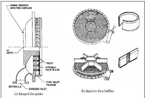
- Integral faceplate.
This plate is secured to the main injector body by brazing in at the periphery and at posts which are an integral part of the main body. A fuel compartment is located immediately behind the faceplate and fed from an inlet passage. The oxidizer compartment is separated from the fuel by a partition. The fuel is injected through orifices drilled in the faceplate, while the oxidizer is injected through orifices drilled in the posts (see fig 5.1a).
- Injector face baffles.
Baffle design is predicated on the assumption that the majority of instability oscillations, along with the driving source, are located in or near the chemical reaction zone in the injector end of the combustion chamber. The baffles minimize influential coupling and amplification of gas dynamic forces within the chamber. Baffles must be strong, have excellent resistance to combustion temperatures and must protrude into the chamber enough to be effective, yet not so far as to act like an individual combustion chamber with is own acoustical characteristics. The number of baffle compartments is always added (see fig. 5.1b).
Figure 5.1: Integral faceplate and Injector face baffles configurations.
- Showerhead.
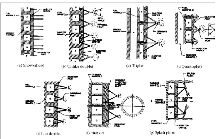
This pattern employs non impinging oxidizer and fuel streams which emerge normal to the injector face. It relies entirely on combustion chamber turbulence for mixing. It is the simplest. It exhibits poor performance in most applications, with the exception of certain cryogenic propellant combinations. This type of injector is seldom used as a thrust-producing injector because of its poor atomization and mixing characteristics, it is often used as a barrier fuel-film cooling element. It is advantageous to use when the forward chamber can be adequately regeneratively cooled but the throat heat flux is excessive for thermal reliability margin or would otherwise require excessive coolant pressure drop (see fig 5.2a).
- Impinging stream type.
The propellants are injected through a number of separate small holes in such a manner that the fuel and the oxidizer streams impinge upon each other. The impinging can be uniplanar, in which all the impinging points are the same distance from the injector face, or biplanar or multiplanar if two or more impinging point distances are used. Many variations on the impinging jet injectors shown in the fig 5.2 are utilized:
o Unlike doublet. In this design the oxidizer and the fuel jets are made to impinge in pairs, thus good liquid phase mixing and atomization is obtained. One of the disadvantages of this injector is that even if the injector holes have
Simona Silvestri 91
been accurately drilled, the resultant angle of momentum vector, or beta angle, will vary with mixture ratio, particularly if a large impinging angle is used. o Like doublet or self impinging. This pattern generally employs self-impinging
pairs of fuel and oxidizer. Mixing is accomplished in the combustion chamber by volatilization on the propellants and by turbulence. It has good combustion stability and moderate performance level. This application has been successful for both cryogenic and storable hypergolic propellant combinations
o Triplet. Two streams of one propellant impinging symmetrically on one stream of the other propellant will eliminate the change of vector angle beta, a resultant of mixture-ratio variation. It has high combustion performance and for this reason it is widely used.
o Quintuplet. Four streams of one propellant impinging on one stream of the other propellant in a symmetrical quintuplet pattern provide excellent mixing and performance. This design has been applied for various propellant combinations.
o Ring slot. This type employs concentric pairs of annular slots which eject the propellants as conical sheets. The slots are so arranged that fuel and oxidizer sheets impinge much in the same manner as in the doublet-type injector.
o Splash plates. This injector is designed for good propellant mixing while the propellants are still in the liquid state. Injected propellants are deflected by the splash plates. The plates will be kept cool by the impinging liquid propellants which do not ignite until they have left the plate.
Figure 5.2: Impinging jet type’s configurations.
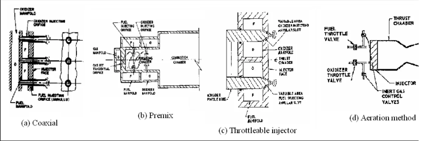
- Coaxial injector (see fig. 5.3a).
This injector employs two concentric tubes for the two propellants, which are injected coaxially. The most common element type uses liquid oxygen/liquid hydrogen and there are two varieties, the shear coaxial and the swirl coaxial. Both usually position the hydrogen in the outer annulus and inject the oxygen in the central jet. The shear coaxial requires a proportionately higher fuel-to-oxygen injection velocity ratio so that sufficient injection momentum can adequately atomize and mix the liquid oxygen jet. It provides a thermally benign environment on the forward chamber wall but it can also cause thermally adverse conditions in the nozzle convergent section if the oxygen droplets are not completely vaporized at the end of the cylindrical chamber and impinge, shutter, and combust on the convergent throat section. Careful attention must be paid in swirl coaxial injector if the elements are positioned too close to the chamber wall.
- Premix (see fig. 5.3b).
Fuel and oxidizer are injected radially into the premixing chamber, where they are mixed before entering the combustion chamber by a gas jet introduced tangentially at the
Simona Silvestri 93
chamber end. The length and diameter of the premixing chamber with relation to the mass flow of the propellants is critical, as is the reaction time of the propellants.
- Throttleable injector (see fig. 5.3c).
Certain requirements for space vehicle missions, such as orbit corrections, rendezvous and docking manoeuvres, and lunar soft landing, demand engine systems capable of thrust control. This is a very effective means of controlling the propellant flows and injector pressure drops at various engine thrust levels. The addition of moving parts , however, causes design complications.
- Aeration method (see fig. 5.3d).
An inert gas is introduced into the injector propellant manifold to reduce the thrust levels. Through variation of the propellant gas mixture ratio, the effective density of the propellants can be varied over a wide range to achieve any desired thrust level without affecting combustion stability. The gas can be supplied by the same source used to pressurize the propellant tanks. This method has increased the range of rocket-engine throttling up to a ratio of 100 to 1.
Figure 5.3: Injector’s types.
5.5 Design calculations
The starting point of any injector design is proper distribution of the fuel and the oxidizer across the injector face at the most advantageous point. Uniform mixture ratio distribution across the injector core elements can maximize performance but may also result in excessive heat flux at the combustion chamber, which could cause thermal failure or require excessive
regenerative coolant circuit pressure drop in high-pressure engines. Anyway injector manifold distribution represents a necessary but not sufficient criterion for design success. Most of the design correlations used to predict drop size are dependent on propellant properties (density and viscosity), ambient pressure, and injection element design parameters (injector pressure drop, orifice diameter, and impingement angle) [46].
The propellant (oxidizer or fuel) injection velocity V can be calculated from the basic relation:
Aρ
m
V = & (5.1)
where
m& is the propellant mass flow rate;
A is the calculated injector orifice area;
ρis the propellant density.
The mass flow rate of propellant and the pressure drop across the injector are related by an equation in the form of:
) / ( 2
ρ
ρ
A p C m& = d i ∆ (5.2) whereAi is the injector nozzle area;
p
∆ is the pressure drop across the injector nozzle;
Cd is the discharge coefficient. For injector nozzles that are essentially short tubes with
rounded inlets, discharge coefficients from 0.97 to 0.99 are attainable. For sharp-cornered tubes or orifice, the discharge coefficient drops to 0.6 to 0.8, primarily because of contraction of the jet cross section.
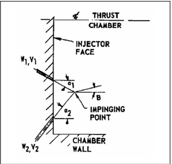
The angle between the thrust chamber axis and the resultant momentum vector of a pair of impinging streams is defined as the beta angle β By definition when the vector is directed toward the chamber wall, the beta angle is positive, and when the vector is directed toward the central axis of the thrust chamber, the beta angle is negative. This angle can be easily calculated from the principle of conservation of momentum(see fig. 5.4):
Simona Silvestri 95 2 2 2 1 1 1 2 2 2 1 1 1 cos cos sin sin tan a V m a V m a V m a V m β & & & & + − = (5.3) where
a1 and a2 are the respective angles between the thrust chamber axis and the streams;
V1 and V2 are the injection velocities.
Figure 5.4: Resultant angle of impinging streams.
5.4.1 Experimental evaluation of injector design
The design of the injector can be improved through experimental testing. Three different types are usually employed.
Hydrostatic pressure test loads are used to determine whether the injector structure withstand the required pressure loads.
Water flow tests are used to evaluate the following design characteristics: the effective injector pressure drop. The data from the water-flow tests can be used to determine the orifice-discharge coefficient and to predict the injector pressure drop for the design propellant, with corrections for density and viscosity; the injection pattern and the impingement can be observed, and faulty operation can be detected and corrected; atomization. Water- flow tests at velocities corresponding to those employed in actual service indicate the quality of atomization to be expected with the actual propellants.
Hot firing tests evaluate fully the true injector operational characteristics, such as performance, combustion stability, and heat-transfer characteristics for main-stage conditions, as well as start-and-stop transients.
5.6 Impinging jet injectors
The like doublet (LD) and unlike doublet (UD) are the most common type of impinging jet injectors elements [47]. The UD element promotes rapid mixing and combustion, whereas the LD element provides a more distributed combustion zone along the combustion axis. The UD element is typically used more often in small thrusters applications, whereas the LD element is used in large scale thrusters where the combustion instability can be a problem. The LD was considered to be utilized in hybrid rocket engine for its simplicity, low manufacturing costs, good atomization and mixing characteristics.
In LD injector equal diameter liquid jets impinge to form a fan-like elliptical liquid sheet. The angle between the jets, 2θ, is generally about 60 deg. The impingement point is typically about five length-to-diameter ratio downstream of the injector face. The fan may be inclined at a small angle
α
toward an adjacent fan of the opposite propellant to promote propellant mixing. The angular coordinate in the plane of the sheet is defined as φ. The mixing efficiency represents the tightness of the mixture ratio distribution about the local injection average and the typical range is from 0.5 to 0.85.The combustion stability is an aspect that has to be considered in this type of injector. Three modes of combustion instability are encountered: non-acoustic bulk mode instabilities (chug), acoustic injection-coupled modes, and acoustic intrinsic instability modes. Chug and injection-coupled instabilities can be avoided by having a sufficiently high injector pressure drop, instead intrinsic instabilities can be avoided by increasing orifice size or decreasing injection velocity.
The modelling of thin sheets formed by impinging jets has been studied by Squire, Taylor, Hasson, Heidmann, Dombrowski and Hooper. When two equal cylindrical coplanar jets collide they from a sheet whose thickness distribution is a function of the jet radius, the radial distance in the sheet, the impingement angle, and the angular position are referred to as a pole along the separation streamline [48]. The physical part was already analyzed in the previous chapter: a small instability is amplified until it reaches a critical wavelength and the sheet breaks into ligaments and then into drops of several sizes.
The atomization behaviour of different Newtonian fluids with a like doublet impinging jet injector under ambient pressure and temperature conditions was studied and compared by H.K. Ciezki et al [49]. The properties of the selected liquids together with the variation of the jet velocity offered the possibility to conduct experiments in a wide range of dimensionless numbers. For all fluids tested the behaviour changed with increasing jet velocity, and thus
Simona Silvestri 97
increasing Reynolds and Weber numbers. Seven types of jet break-up modes can be identified:
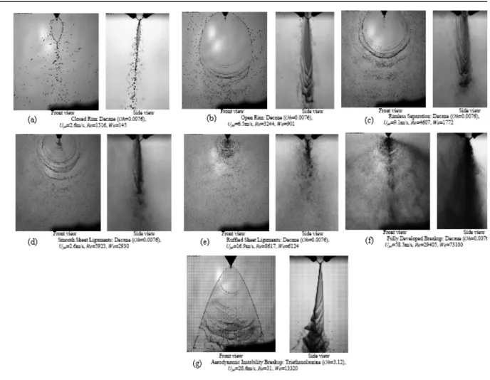
- Closed Rim (see fig. 5.5a). From the impingement point the liquid expands radially creating a flat and thin sheet, perpendicular to the jets collision plane, bounded by a distinct rim. At the lower end of the sheet the two arms of the rim impinge under a distinct angle and a single stream is formed. This latter breaks-up into droplets.
- Open Rim (see fig. 5.5b). This sheet is not totally surrounded by a rim. A flapping motion of the lower part of the this breaks up the rim and the sheet into ligaments and drops so that the arms of the rim are not in contact. This is due to Kelvin-Helmholtz instability. Also larger droplets could shed from the rim according to the capillary instability.
- Rimless Separation (see fig. 5.5c). Distinct rims are not visible. The rupture of the almost circular liquid sheet starts at the sides with the separation of parts of the sheet in the region of Kelvin-Helmholtz instability. The droplets shed directly from the sheet and part of the sheet decays periodically downstream.
- Smooth Sheet Ligaments (see fig. 5.5d). This type of break-up is similar to the Rimless Separation but here a periodic separation of bow-shaped ligaments from the sheet occurs, which decay after into droplets downstream. The separation of these ligaments is supported by the presence of holes in the sheet, which grow in size. - Ruffled Sheet Ligaments (see fig. 5.5e). Wavy structures occur directly on the sheet.
The bow-shaped ligaments, seem to be separated significantly earlier from the sheet so that the sheet size seems reduced significantly.
- Fully Developed Break-up (see fig 5.5f). A direct decay into droplets without the formation of ligaments occurs. The Reynolds number of this experiment indicates that the flow in the injector passages is turbulent. Moreover the separated droplets are mainly concentrated in bow-shaped clouds, so that waves of droplets spread downstream periodically.
- Aerodynamic Instability Break-up (see fig. 5.5g). At low jet velocity there are no droplets that are separated from the rim. The sheet is long and narrow and its surface is smooth. Aerodynamic instability generates a flapping motion of the sheet. No capillarity instabilities can be observed in this region.
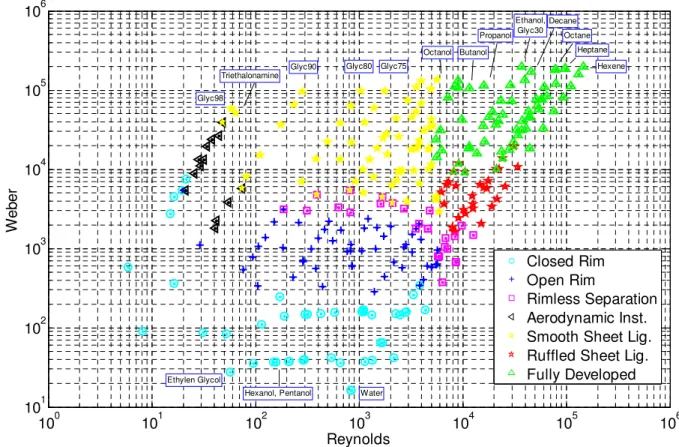
The experiments show that: the Closed Rim mode occurs for all fluids in the region of 102<Re<104 below a constant Weber number that is approximately We<300. The lower
Weber indicates that in this region the surface tension forces are dominant in comparison to the inertial forces; the Rimless Separation mode presents the transition between the Open Rim mode and the two modes with ligaments structures for fluids with Ohnesorge numbers in the range of 0.044<Oh<0.25; the Smooth Sheet with Ligaments pattern is found above a nearly constant Weber, We≈4⋅103 in the Reynolds number range from 8⋅10 to 5⋅103; the Ruffled Sheet with Ligaments structures mode occurs for higher Reynolds; the Fully Developed Break-up regime is located in the region of highest Re and We, Re<5⋅103 and We>1⋅104; at low Reynolds numbers the Aerodynamic Instability Break-up mode occurs. The experiments can be positioned in a Reynolds vs. Weber numbers diagram shown in the fig 5.6 Further investigations are necessary for a better understanding of the governing processes in all break-up modes.
Simona Silvestri 99
Figure 5.6: Reynolds-Weber regime diagram.
5.5.1 Governing equations
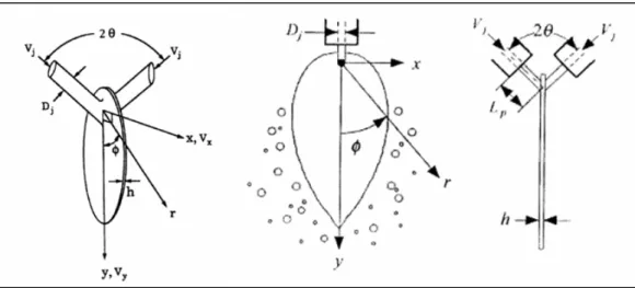
The mathematical formulation developed by Dombrowski and Johns [50] for fan-spray nozzles can also be applied to the sheet formed by two impinging jets. Hasson and Peck [51], suggesting that a section though the jet in a plane parallel to the sheet is an ellipse and equating the mass flow input in an angular element of the ellipse to the output in the corresponding element of the sheet, found that:
2 3 2 ) cos cos 1 ( sin
θ
φ
θ
− = R hr (5.4) whereR is the radius of the liquid jet;
h is the sheet thickness distribution;
r is the radial distance;
φ is the angular position;
2θ is the angle between the jets (see fig. 5.7):
100 101 102 103 104 105 106 101 102 103 104 105 106 Reynolds W e b e r Hexene Heptane Octane Decane Water Ethanol, Glyc30 Propanol Butanol Hexanol, Pentanol Octanol Ethylen Glycol Glyc75 Glyc80 Glyc90 Triethalonamine Glyc98 Closed Rim Open Rim Rimless Separation Aerodynamic Inst. Smooth Sheet Lig. Ruffled Sheet Lig. Fully Developed
Figure 5.7: Sheet formed by impinging jet.
When the sheet spreads away under the influence of the viscous inertia surface tension and pressure forces the ligaments are formed, Dombrowski and Johns [50] found for the diameter of those ligaments the following expression:
5 1 3 5 2 8 4 6 1 2 2 2 3 1 6 6 2 1 3 4 2 + ⋅ = σ fρ U kρ µ . U ρρ σ k f d L L L (5.5)
where f is the total wavelength, given by
∫
= t L dt h U f 0 2 2ρ
σ
ρ
(5.6) whereσ
is the liquid surface tension;µ is the liquid viscosity;
ρ is the density of the surrounding medium; L
ρ
is the density of the liquid,U is the velocity of the radiating sheet;
k is a constant obtained assuming a hyperbolic relationship between the thickness h and the time t (i.e. ht=k).
For a radiating sheet of uniform velocity the thickness at any point could be given by
h=k1
Simona Silvestri 101 thus: 2 3 2 1 ) cos cos 1 ( sin
θ
φ
θ
− = R k (5.8)Assuming the equation (5.5) still holds for the near cylindrical ligaments formed at the sheet break-up and choosing in that equation f to be equal to 12 is found that the ligaments diameter and the drops diameter is respectively:
5 1 3 5 7 4 1 6 1 4 2 2 1 72 60 . 2 1 9614 . 0 + =
σ
ρ
ρ
µ
ρρ
σ
L L L U k U k d (5.9) 6 1 2 1 3 1 ) ( 3 1 2 3 + = L L L d d d dσ
ρ
µ
π
(5.10) where U is the velocity of the radiating sheet and it was defined by Dombrowski as the mean relative air wave velocity(
22)
/2 2 1 U U U = + (5.11) whereU1 and U2 are respectively the relative velocities over the upper and lower sheet surfaces.
If the environment is a quiescent gas and the radial distance in the sheet, r, is large enough, the inward velocity component of the attenuating sheet is negligible.
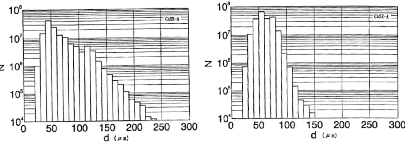
Typical results for the initial drop size distribution and the drop size distribution in its final state are shown in fig 5.8a and 5.8b. The comparison between representative experimental data and results is shown in fig 5.9.
Based on laboratory experiments at reduced-flow conditions, the impact waves seem to dominate atomization in this type of injector. These impact waves are a major factor in the resulting drop size distribution and the atomization frequency, which may play a major role in combustion instability. However, their importance at very high ambient density has not been established.
Figure 5.8: Predicted drop size distribution (a) initial drop size distribution after primary atomization,
(b) drop size distribution in its final state.
Figure5.9: Comparison between measured and predicted drops in Rosin-Rammler expression.
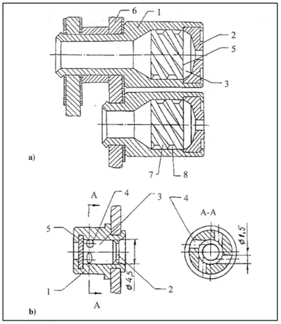
5.7 Swirl injectors
Swirl injectors are predominantly used in the Russian Liquid Rocket Engine gas generator and in combustion chambers with pressurized feed systems or gas-generator cycles [45]. As shown in fig. 5.10 each injector has a casing (1) brazed into the bottom of the assembly. The casing has a nozzle (2) and an axisymmetric cavity (3) connected to the liquid manifold through tangential passages (4). The bottom (5) is flared out and welded in the casing (1) forming a vortex chamber (6). In the recent injector designs, the bottom (5) is profiled to optimize the shape of the passage cross section of the vortex chamber (6). In screw-conveyer
Simona Silvestri 103
injectors (fig. 5.10a), a screw-conveyer swirler (7) whose external passages (8) serve as tangential passages (4) is fitted into the casing (1).
Figure 5.10: Monopropellant swirl injectors with a)screw conveyer and b) tangential passages.
A single swirl injector is often referred to as a simplex or pressure-swirl atomizer. There are two types of simplex nozzles: solid-cone and hollow-cone atomizer. The solid-cone atomizer atomizes a liquid by swirling it, while permitting most of the flow to go through a middle cylindrical hole, providing spray drops at the center of the spray pattern. Hollow-cone atomizers provide better atomization and radial liquid distribution, rendering them the preferred configuration for combustion application.
A typical swirl-coaxial injector is shown in fig. 5.11. Liquid is introduced tangentially into the counter post trough passages [52]. The liquid stream tangential velocity creates a swirling vortex flow within the center post tube. The tube does not flow full, but inside contains a thin swirling film along the inner wall with a hollow gas core sheet. The swirling film exits the tube in the form of a hollow cone sheet. While this sheet readily self-atomizes, a coaxial flow of gas greatly enhances and accelerates the sheet break-up process by disturbing the liquid film that emerges from the injector post. The atomization process is a combination of two
factors: the tendency of the conical liquid sheet to disintegrate as a it swirls and stretches, and the tendency of the coaxial gas flow to accelerate sheet break-up due to is momentum transfer to the conical sheet emerging at the exit of the post.
Figure 5.11: Schematic of a swirl coaxial gas/liquid injector.
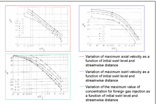
The effects of various initial swirl levels on the development of the mean flow are shown in fig.5.12. Clearly, increasing the initial swirl level increases the rate of the mixing of all of the mean-flow variables.
Simona Silvestri 105
Transversal axial velocity profiles and transverse tangential swirl velocity profiles are shown in the fig. 5.13, both for the highest initial swirl level for the test. The outer portions of the tangential velocity profiles decay in a manner similar to an inviscid vortex, but the inner portion is dominated by viscous effects. The tangential velocity at the centreline is zero rather than the infinitive value for inviscid vortex.
Figure 5.13: Profiles of the velocity.
It is possible to define the swirl number (S) as:
j Mr T S * = (5.12) where
M is the integral of the pressure plus the axial momentum;
T* is the total initial angular momentum;
rj is the jet radius:
∫
+ = A dA U P M (ρ
2) (5.13)∫
= A UWdA T*ρ
(5.14)Figure 5.14: Half-radius growth as a function of swirl number
At the increasing of the swirl number the axial velocity profile changes until a substantial flow reverses on the axis. This is due mainly to the large radial pressure gradient that is produced by the swirl. The mean-flow terms show a simple, direct relationship between swirl magnitude and radial pressure gradient. When the outer fluid is stationary or at least not swirling, then the static pressure drops rapidly from the external value to a low value on the axis. The actual total variation is a function of swirl rate and it is thus largest for small ratio of axial direction to diameter (x/d) where the swirl has not yet decayed significantly. the result is an adverse pressure gradient along the axis with increasing x/d. for large enough swirl, this gradient becomes strong enough to produce flow separation and reversal.
Droplet mean properties of kerosene spray are presented in Appendix A to given an example as the variation of droplet distribution changes with the variation of the axial coordinate and the swirl number.
5.7.1 One-equation models
A treatment based upon an integrated Turbulent Kinetic Energy equation model has been applied to a swirling wake case:
∫
∫
∫
−∫
− ∂ ∂ − + ∂ ∂ − = ∂ ∂ ) ( 0 ) ( 0 ) ( 0 2 3 ) ( 0 ) ( x b b x b x D x b rdr k l C rdr r W r W wv rdr r U uv rdr Uk xρ
ρ
ρ
ρ
(5.15)Simona Silvestri 107
where
x is the axial coordinate;
r is the radial coordinate;
b is the mixing zone width;
ρ
is the mean density;U is the mean axial velocity;
u , v and w are respectively the fluctuating axial, normal and transverse velocity;
k is the turbulent kinetic energy;
W is the mean transverse velocity;
CD is an empirical constant;
l is the length scale in the turbulence model.
Taking in analogy the equations (12), (18) and (135) in reference [52] an ordinary differential equation for the turbulent kinematic viscosity,
ν
T, in function of the axial coordinate is given by:dx dU U dx dI b dx dI I b C U C I I U C I I U C dx d T D T T T ∞ ∞ ∞ ∞ ∞ − + − + = 2 2 4 2 2 1 1 2 2 3 2 1 3 2 3 1 2 2 3
ν
ν
ν
ν
(5.16) where ) ( 3 x b l C = (5.17) ≡∫
∞ b y d b y U U x I j l 0 1( ) (5.18)∫
∂ ∂ ≡ ∞ l j b y d b y b y U U x I 0 2 2 ) / ( ) / ( ) ( (5.19) ∂ ∂ − ∂ ∂ ≡∫
∞ ∞ ∞ b r d b r b r U W b r U W b r U W x I l 0 2 3 ) / ( ) / ( / / ) / ( ) / ( ) ( (5.20)5.7.2 Different configuration’s types
A bicentrifugal swirl injector consists of an inner simplex atomizer and an outer swirler [53]. The fluid is injected tangentially into both the inner and outer swirl chambers. the
swirling fluids proceed down the length of the chamber, are slung out into the chamber, and then coalescence into a single hollow cone if their trajectories intersect. In addition to the possibility of high thrust per element, this injector type features a wider range of throttleability, an increased margin from combustion instability, and reduced pressure drop through the injector, which can result in a decreased demand on rocket turbo machinery. Bicentrifugal swirl injectors are used extensively in the Russian rocket program.
An innovative vortex injection hybrid rocket engine (VIHRE) has been developed [54]. It is based on the concept of cyclonic flow and the use is expected in commercial and military applications due to the favourable features that it offers. The improved performance granted by VIHRE can be attributed to its unique internal flowfield that is dominated by swirling bidirectional motion (see fig 5.15a). The corresponding coaxial, counter-flowing vortex pair increases surface erosion while promoting mixing and turbulence. Other injection configurations employ fore end and distributed tangential injectors. A dual-end-burning hybrid grain that is driven by unidirectional vortex motion is also possible (see fig. 5.15b). In this case, two cylindrically shaped fuel cartridges are placed a small distance apart of both ends of the chamber. Swirl injectors are then employed to produce a spiralling stream that sweeps across the exposed fuel surfaces before wheeling its way out of the chamber; the gas expulsion is achieved through the central orifice perforated in the aft cartridge.