UNIVERSIT
ÀDI
PISA
F
ACOLTÀ DII
NGEGNERIADipartimento di Ingegneria Meccanica, Nucleare e della Produzione Dottorato in Sicurezza Nucleare e Industriale
Philosophy Doctor Thesis
In Nuclear and Industrial Safety
BWR Instability Analysis by Coupled 3D Neutron-Kinetic
and Thermal-Hydraulic Codes
Tutors:
________________________ ______________________
Prof. Francesco D’Auria Prof. Walter Ambrosini
Candidate:
___________________________________
Antonella Lombardi Costa
ABSTRACT
The main aim of this thesis is to contribute to the study of the Boiling Water Reactor (BWR) instability phenomena. The RELAP5-MOD3.3 thermal-hydraulic system code and the PARCS-2.4, 3D neutron kinetic code were coupled to simulate BWR transients. Different algorithms were used to calculate the Decay Ratio (DR) and the natural frequency (NF) from the power oscillation signals obtained from the transient calculations, as two typical parameters used to provide a quantitative description of instabilities. The validation of a code model set up for the Peach Bottom-2 BWR plant is performed against Low-Flow Stability Tests (LFST).
The thesis has the following organisation. Chapter 1 deals with general aspects, starting with the present level of the Light Water Reactor (LWR) development, addressing the specific problem of instability in BWRs and finally analysing the issue of the current tools to investigate the phenomenon. Chapter 2 describes the LFST performed in the Peach Bottom BWR, the perturbation events studied and the methodology adopted to analyse them. Chapter 3 presents the codes and the methodology utilized to perform the calculations and the analyses of the events. In Chapter 4, results considering steady state and transient reactor conditions will be presented and discussed. Finally, Chapter 5 describes the obtained conclusions and the contributions of this work to the study of BWR stability.
SOMMARIO
Lo scopo principale di questa tesi è contribuire allo studio dei fenomeni di instabilità dei reattore al acqua bollente (BWR). Il codice termo-idraulico RELAP5-MOD3.3 ed il codice di cinetica neutronica 3D PARCS-2.4, sono stati accoppiati per simulare i transitori del reattore BWR. Algoritmi diversi sono stati usati per calcolare la Decay Ratio (DR) e la frequenza naturale (NF) dei segnali di oscillazione della potenza ottenuti dai calcoli di transitorio, come due parametri tipici per fornire una descrizione quantitativa della instabilità. La validazione di un modello di codice preparato per l’impianto BWR Peach Bottom-2 è compiuta confrontando i risultati dei calcoli con i dati sperimentali di prove della stabilità in basso-flusso, i Low-Flow Stability Tests (LFST).
La tesi è organizzata nel modo seguente. Il Capitolo 1 tratta aspetti generali, cominciando con il livello attuale dello sviluppo dei reattori ad acqua leggera (LWR), indirizzando lo specifico problema dell'instabilità nei BWRs e infine analizzando il problema degli strumenti correnti per investigare il fenomeno. Il Capitolo 2 descrive i LFST eseguiti nel reattore BWR Peach Bottom, gli eventi perturbativi studiati e la metodologia adottata per compierli. Il Capitolo 3 presenta i codici e la metodologia utilizzata per eseguire i calcoli e le analisi degli eventi. Nel Capitolo 4, sono presentati e discussi i risultati considerando lo stato stazionario e il transitorio del reattore. Infine, il Capitolo 5 descrive le conclusioni ottenute ed i contributi di questo lavoro per lo studio della stabilità dei reattori BWR.
RESUMO
O principal objetivo desta tese é contribuir para o estudo do fenômeno de instabilidade em Reatores a Água Fervente (BWR). O código termo-hidráulico RELAP5/MOD3.3 e o código de cinética neutrônica 3D PARCS/2.4 foram acoplados para simular transitórios em um BWR. Dois algorítimos foram utilizados para calcular os parâmetros Decay Ratio (DR) e Frequencia Natural (NF) dos sinais de oscilação de potência. DR e NF são parâmetros típicos utilizados para quantificar as instabilidades. O reator BWR Peach Bottom-2 foi modelado para o sistema de códigos adotado e a validação foi feita para a série de testes de estabilidade Low-Flow Stabilit Tests (LFST).
A tese é organizada em cinco capítulos: o Capítulo 1 trata de aspectos gerais, começando por apresentar o atual nível de desenvolvimento dos Reatores a Água Leve (LWR), passando pelo problema específico da instabilidade em BWRs e finalizando por descrever os métodos correntemente utilizados para o estudo do fenômeno. O Capítulo 2 descreve os testes de estabilidade realizados no reator Peach Bottom, os eventos de perturbação a serem considerados e a metodologia adotada para estudá-los. O Capítulo 3 apresenta os códigos e a metologia utilizada para o procedimento dos cálculos e das análises dos eventos. No Capítulo 4, são apresentados e analisados os resultados relativos aos cálculos obtidos para o estado estacionário e para os transitórios. O Capítulo 5 descreve as principais conclusões alcançadas e as contribuições deste trabalho para o estudo da instabilidade em BWRs.
ACKNOWLEDGEMENTS
I am grateful to God and several people that were fundamental for the development and good conclusion of this work. In particular, I would to thank to:
@ CAPES for the PhD grant.
@ The University of Pisa for giving me the opportunity to develop my PhD studies here. @ My tutor, Prof. Francesco D’Auria for the initial encouragement and support to carry out
this thesis.
@ My tutor, Prof. Walter Ambrosini for his valuable suggestions, corrections, permanent help and patience.
@ Prof. Marino Mazzini, course director, for the support.
@ My husband, Geraldo, and my daughter, Bianca, for their love, patience and understanding in all the moments.
@ My colleagues of the San Piero a Grado Nuclear Research Group for the hospitality and support.
I dedicate this work to
CONTENTS
INTRODUCTION ... 11
CHAPTER I – GENERAL CONSIDERATIONS ... 15
1.1. The Four Generations of Reactors ... 15
1.2. BWR – Boiling Water Reactors ... 17
1.2.1. General ABWR Characteristics ... 17
1.2.2. General BWR Characteristics ... 19
1.2.3. Two-Phase Flow ... 21
1.2.4. Relevant BWR transients ... 24
1.2.4.1. Overpressurisation ... 24
1.2.4.2. LBLOCA ……... 25
1.2.4.3. Control Rod Withdrawal ... 25
1.2.4.4. Feedwater Temperature Decrease ... 26
1.2.4.5. Main Circulation Pump Flow Rate Increase ... 26
1.2.4.6. Anticipated Transient Without Scram (ATWS) ... 26
1.2.4.7. Core Instability Events ... 27
1.2.5. Power and Flow Instabilities in BWRs ... 27
1.2.5.1. BWR Power Instabilities ... 28
1.2.5.2. BWR Flow Instabilities ... 30
1.2.6. BWR – Power/Flow Map ... 31
1.2.7. Induced and Inadvertent BWR Instabilities ... 32
1.2.7.1. Inadvertent BWR Instabilities ... 33
1.2.7.2. Induced BWR Instabilities ... 34
1.2.8. Methods and Tools to Study BWR Instabilities ... 35
1.2.8.1. Mathematical Models ... 35
1.2.8.2. Computer System Codes ... 37
1.2.8.2.1. Thermal-Hydraulic Codes ... 38
1.2.8.2.2. Neutronic Codes ... 38
1.2.8.2.3. Coupling between Thermal-Hydraulic System and 3D Neutronic Codes ... 39
1.2.9. The Decay Ratio Parameter ... 43
CHAPTER 2 – STUDIED EVENTS ... 49
2.1. Peach Bottom 2 and the Low-Flow Stability Tests ... 49
2.2. Proposed Sensitivity Cases ... 58
2.2.1. Feedwater (FW) Temperature Decrease ... 59
2.2.2. Recirculation Pump Trip (RPT) ... 59
2.2.3. Control Rod Banks Movement ... 60
CHAPTER 3 – ADOPTED CODES AND MODELS ... 63
3.1. Adopted Computational Codes ... 63
3.1.1. RELAP5 ... 63
3.1.2. PARCS ... 64
3.2. Other Computational Tools ... 67
3.2.1. ADRI ... 67 3.2.2. DRAT ... 68 3.3. Coupling Process ... 70 3.4. Thermal-Hydraulic Model ... 72 3.5. Neutronic Model ... 77 3.6. Calculation conditions ... 79
CHAPTER 4 – ANALYSES AND RESULTS ... 83
4.1. Steady State Results ... 83
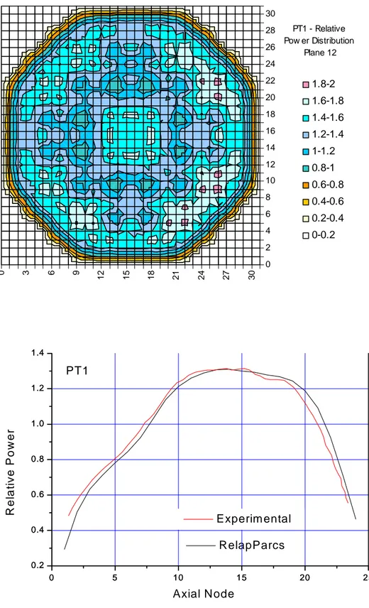
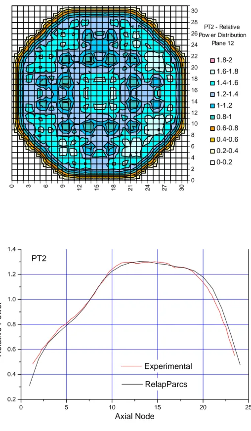
4.2. Transient Results ... 91 4.2.1. Pressure Perturbation ... 91 4.2.1.1. Case PT1 ... 93 4.2.1.2. Case PT2 ... 103 4.2.1.3. Case PT3 ... 108 4.2.1.4. Case PT4 ... 113
4.2.1.5. Some Sensitivity Cases ... 119
4.2.1.6. Pressure Perturbation – Conclusions ... 125
4.2.3. Recirculation Pump Trip ... 131
4.2.3.1. Case 1 – Sudden Pump Trip ... 131
4.2.3.2. Case 2 – Permanent Pump Trip ... 137
4.2.3.3. Recirculation Pump Trip – Conclusions ... 139
4.2.4. Control Rod Bank Movement ... 140
4.2.4.1. Case 1 – Control Rods Banks Withdrawal in Time Steps ... 140
4.2.4.2. Case 2 – Continuous Control Rod Banks Withdrawal ... 144
4.2.4.3. Case 2 – Decay Ratio Analysis ... 153
4.2.4.4. Case 2 – Three-Dimensional Power Assessment ... 155
4.2.4.5. Sensitivity Analyses... 156
4.2.4.6. Control Rod Banks Continuous Withdrawal – Conclusions ... 160
4.2.5. Stability Boundary ... 162
4.2.5.1. Transient 1 – Mass Flow Rate Increasing ... 162
4.2.5.2. Transient 2 – Slow Control Rod Bank Movement ... 163
4.2.6. Pressure Perturbation Following CRB Removal ... 166
4.2.6.1. Case 1 ... 166
4.2.6.2. Case 2 ... 168
CHAPTER 5 – CONCLUSIONS ... 173
REFERENCES ... 179
ACRONYMS ... 189
ANNEX A – Application of ADRI Methodology to Time Series Oscillations at Forsmark NPP ... 191
ANNEX B – Example of cross section library format ... 197
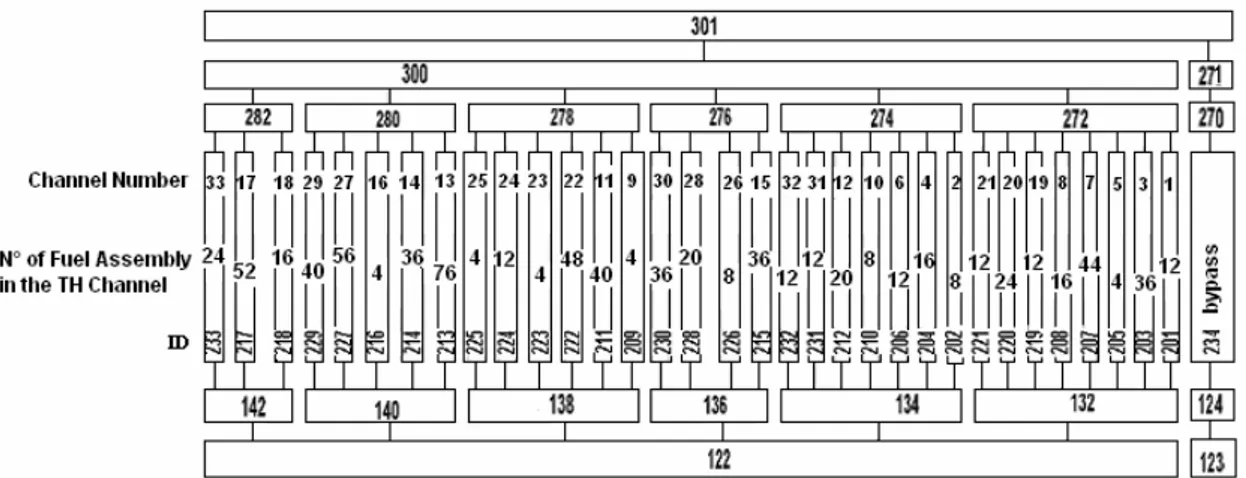
ANNEX C – Peach Bottom – 132 Heated Core TH Channels ... 205
INTRODUCTION
The effects on the environment of burning fossil fuels and the increase in world electricity demand have brought renewed interest in low polluting energy sources, as the nuclear power. In the last four decades, the nuclear power industry has been upgrading and developing light water reactor
(LWR) technology, driving the attention to more economical, minimal waste production, impervious to
proliferation and, mainly, safer systems.
In particular, the Boiling Water Reactors (BWRs) are considered also from the point of view of instability events. Coupled thermal-hydraulic and neutronic BWR instabilities are caused by interdependencies between thermal-hydraulic and reactivity feedback parameters such as the void reactivity coefficient. Since instabilities were observed in Forsmark 1 (1987) and later also in LaSalle (1988), authorities in all countries required a review of stability features of their BWRs.
BWR instabilities may occur when, starting from a stable operating condition, changes in system parameters bring the reactor towards an unstable region. Consequently, state variables identifying the reactor working conditions are observed to oscillate in different ways depending of the modalities of the departure from the stable operating point. From the point of view of the BWR safety, the most important type of power instability involves reactivity and power oscillations excited by thermal-hydraulic mechanisms. Therefore, in order to design more stable and safer core configurations, experimental and theoretical studies about BWR stability have been performed to characterise the phenomenon and to predict the conditions for its occurrence.
Simulations of complex scenarios in NPPs, as those involved in BWR instabilities, were improved by the utilization of coupled thermal-hydraulic (TH) and neutron kinetics (NK) system codes. This technique consists in incorporating three-dimensional (3D) neutron modelling of the reactor core into system codes, mainly to simulate transients that involve asymmetric core spatial power distributions and strong feedback effects between neutronics and reactor thermal-hydraulics. In all the relevant BWR transient scenarios, the use of coupled 3D techniques is justified by the broad variation in the axial linear power distribution as a function of time.
In this work, the RELAP5/MOD3.3 thermal-hydraulic system code and the PARCS/2.4 3D neutron kinetic code were adopted to simulate coupled instability phenomena in the Peach Bottom BWR and to investigate the possible mode of oscillations that could be observed in the reactor when it is brought to unstable conditions. A literature research was also performed about this issue, identifying experimental and accidental BWR instability events, as well as models and tools to investigate BWR stability, including the use of the coupled codes for NPP analyses in general. Several works have been attentively revised in this purpose, relating the following aspects:
types of BWR inadvertent occurrences and tests: pump trip, flow reduction, pressure disturbance, perturbation of the feedwater flow rate, void “flashing” (occurrence of sudden boiling in a natural circulation BWR), turbine trip, low-flow/high-power stability tests, etc.;
occurred BWR plant events: Ringhals 1, Forsmark 1 and 2, Peach Bottom, LaSalle, Leibstadt, Laguna Verde, Oskarshamn, Cofrentes, etc;
different TH/NK coupled codes: BF1/ENTREÉ, RELAP5-3D, BF1/RAMONA, MARS/MASTER, RETRAN-3D, BF1/NEM, TRAC-BF1/SKETCH-N, RELAP5/PANBOX/COBRA, RELAP5/PARCS, etc..
In addition, a recent publication of the Nuclear Energy Agency provided by the CRISSUE-S project presents important contributions about the application of neutronic/thermal-hydraulic coupled systems in LWR technology to be considered in this work.
The main aim of this thesis is to contribute to the study of BWR instability phenomena. The RELAP5-MOD3.3 thermal-hydraulic system code and the PARCS-2.4 3D neutron kinetic code were coupled to simulate BWR transients. Different algorithms were used to calculate the Decay Ratio (DR) and the natural frequency (NF) from the power oscillation signals obtained from the transient calculations, as two typical parameters used to provide a quantitative description of instabilities. The validation of a code model set up for the Peach Bottom-2 BWR plant is performed against Low-Flow Stability Tests (LFST). These four series of Stability Tests were performed at Peach Bottom Unit 2 in 1977 at the end of cycle 2 in order to measure the reactor core stability margins at the limiting conditions used in design and safety analysis.
In this work, four typical transients are investigated in order to estimate the degree of stability of each addressed operating condition. Their main features are described below.
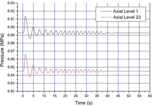
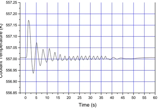
1 – Pressure Perturbation (PP) – To simulate the real core behaviour during the PP, the reactor was disturbed in the turbine with pressure spikes of 0.055 MPa during 1 second. A positive pressure wave propagates from the turbine to the reactor pressure vessel (RPV) and reaches the core. The event causes an increase of the mass flow rate in the core channels and a consequent core void fraction decrease. Therefore, there is a positive reactivity insertion bringing to the increase and in-phase oscillation of the total power. It was observed that in such cases the oscillations decrease in few seconds, reaching the stable operation in both experimental and calculation cases.
2 – Feedwater (FW) Temperature Decrease – This event reduces the volume occupied by steam in the core and causes an increase in the moderation and in the fission power. However, the perturbation does not result in a very significant variation in the power evolution and the reactor showed to be safe in the cases of FW temperature variations considered in this work.
3 – Recirculation Pump Trip (RPT) – The stop of a recirculation pump causes a sharp decrease in the core flow, which generates a significant negative reactivity insertion in the core that tends to reduce power and, consequently, the amount of steam generated. Power oscillations are caused by the reactivity void feedback effects at relatively large power-to-flow ratios. It was observed by the calculations that the power and all the others related thermal-hydraulic parameters presented in-phase oscillations that return to the steady state operating conditions after about 20 seconds.
4 – Control Rod Bank Movement – The transient is simulated by the withdrawal of control rod banks from the core. In this event, in-phase and out-of-phase oscillations were observed. The of-phase one is a relevant type of BWR instability because of safety implications. During out-of-phase instabilities, power oscillates so that average power could remain essentially constant. Usually, the safety systems in a BWR scram the reactor according with received average power signals and then large-amplitude out-of-phase oscillations could be established in the core without resulting in an automatic scram.
The thesis has the following organisation. Chapter 1 deals with general aspects, starting with the present level of LWR development, addressing the specific problem of instability in BWRs and finally analysing the issue of the current tools to investigate the phenomenon. Chapter 2 describes the Low-Flow Stability Tests performed in the Peach Bottom BWR, the perturbation events studied and the methodology adopted to perform them. Chapter 3 presents the codes and the methodology utilized to perform the calculations and the analyses of the events. In Chapter 4, results considering steady state and transient reactor conditions will be presented and discussed. Finally, Chapter 5 describes the obtained conclusions and the contributions of this work to the study of BWR stability.
1. GENERAL CONSIDERATIONS
Presently available projections point out significant increases in the global population due
per capita energy consummation for the next years, with a consequent increase in the electricity
demand. Therefore, the importance of the available sources of energy cannot be underestimated. The effects on the environment of burning fossil fuels have brought renewed interest in low polluting energy sources, as the nuclear power is. In the last four decades, the nuclear power industry has been upgrading and developing light water reactor technology, and has been preparing to meet the future demand for energy.
The 93 presently operating BWRs, out of the more than 440 nuclear power plants installed worldwide, contribute with about 21.0 % of the total produced nuclear power (Table 1.1). These plants have reached very ambitious goals of safety and reliability, together with high availability factors, notwithstanding the flow instability and thermal-hydraulic oscillations that may affect BWRs under particular operating conditions.
Tab. 1.1. Nuclear power reactors in operation worldwide *.
Type N° of Units Total MW(e)
BWR 93 83405 FBR 2 793 GCR 22 10664 LWGR 16 11404 PHWR 42 21376 PWR 267 241946 Total 442 369588
* Data from IAEA (July 2006)
1.1. The Four Generations of Reactors
The different nuclear reactor designs appeared in the history of nuclear technology are categorized according to generations as can be seen in the scheme of the Figure 1.1. Each generation incorporates evolutionary improvements, with revolutionary concepts to take the next step in reactor technology:
Generation I. These were the prototype commercial reactors of the 1950s and 1960s. Generation II. These are the reactors deployed in the 1970s and 1980s and currently
and the PWRs, and, in Canada, the CANDU heavy-water reactors.
Generation III. These reactors include the advanced boiling water reactors (ABWR), the System 80+ advanced pressurized water reactor (APWR), and the AP600 passive-design reactor. These passive-designs were developed in the United States and certified by the U.S. Nuclear Regulatory Commission in the 1990s. ABWRs and APWRs have been built and are in operation in other countries around the world.
Generation III+. These are reactors that can be deployed by 2010. They have been under development during the 1990s and are in various stages of design and implementation now. They include the pebble-bed modular reactor (PBMR) and the AP1000. Both have passive safety designs and the PBMR is gas-cooled.
Generation IV. These reactors will probably be deployed by 2030 and are expected to be
highly economical, incorporate enhanced safety, produce minimal waste, and be impervious to proliferation. The International Reactor Innovative & Secure (IRIS) project reactor is the Generation IV reactor farthest along in development. It is a light-water reactor (LWR) incorporating advanced engineering to increase safety and reduce operational costs. Another Generation IV reactor is the gas turbine modular helium reactor (GT-MHR) that has passive safety features and is gas-cooled.
Data from Argonne National Laboratory.
1.2. BWR – Boiling Water Reactors
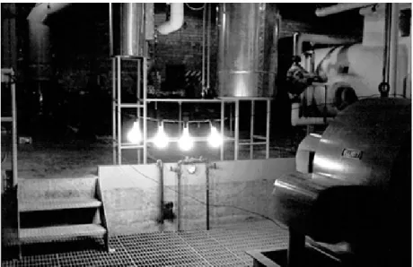
BWRs were developed by ANL (Argonne National Laboratory) during the 1950s and 1960s. On December 20, 1951, Experimental Breeder Reactor 1 (EBR-I) lighted four bulbs with the first usable amount of electricity from nuclear energy in the world (Figure 1.2). Designed, built and operated by Argonne National Laboratory, EBR-I was the first reactor built at what is now called the Idaho National Engineering Laboratory (www.anl.gov/Science_and_Technology/History).
Fig. 1.2. First Atomic Light: EBR-1, first reactor in world to produce electricity. Arco, Idaho, 1951.
Photo: www.anl.gov
There was a series of experimental boiling reactor experiments (BORAX) starting in 1953, designed to study aspects of boiling reactor behavior. The lessons of the early experiments BORAX led to the design of the Experimental Boiling Water Reactor (EBWR) and commercialization, initially by General Electric, starting at the Dresden unit. The first large-scale utility-owned BWR was the 200 MWe plant at Dresden. It started operation in 1960 and ran until 1978. BWRs will be described with greater detail in section 1.2.2.
The favorable characteristics and the operating experience of the BWR technology brought to developing safer and more economical ABWR (Advanced Boiling Water Reactor) technology. ABWR is being described in the next section.
1.2.1. General ABWR Characteristics
According with the description by Tsuji et al. [1], the principal ABWR components are the Reactor Internal Pump (RIP) system, the Fine Motion Control Rod Drive (FMCRD) system, the Reinforced Concrete Containment Vessel (RCCV), the three division high pressure Emergency
Core Cooling Systems (ECCSs), and high-efficiency turbine system. The first ABWRs developed in this process were adopted for the No. 6 and No. 7 units of Kashiwazaki-Kariwa Nuclear Power Station (K-6 and K-7) of Tokyo Electric Power Company. K-6 construction began in September 1991 and commercial operation commenced on 7 November 1996. K-7 construction began in March 1992 and commercial operations commenced on 2 July 1997 [1].
The main characteristics of the ABWRs are:
The ABWR building is three times smaller than those of the present BWR buildings, resulting in a shorter construction time and expenses.
Simplification of the primary recirculation loop by the adoption of Reactor Internal Pumps (RIP). These special pumps eliminate the large external loop pipes connected to the reactor pressure vessel.
The control rods are powered electrically and hydraulically. This reduces the chances of failure in terminating the nuclear reaction and allows for fine-tuning the plant power to produce a given amount of electricity during seasonal extremes conditions.
The systems are electronically separated: each division has access to its own sources of redundant electricity, including batteries and an emergency diesel generator.
The systems have the capability of always keeping the reactor core covered with water. Because of this and the thermal margins in fuel design, costly transients which require the plant to be shut down have been reduced to less than one per year.
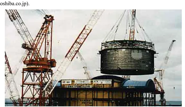
Figures 1.3 and 1.4 show respectively, the transport of the RCCV and the foundations of the reactor pressure vessel, during the ABWR construction phases in Japan (photos: www.toshiba.co.jp).
Fig. 1.4. ABWR in Japan – The foundations of the reactor pressure vessel.
1.2.2. General BWR Characteristics
In a BWR, the steam is formed in the reactor itself and goes directly to the turbines. Then, it operates in a direct cycle. The water becomes radioactive in passing through the reactor core and then all of the components of the steam utilization system, the turbines, condenser, preheaters, pumps, piping, and so on, must be shielded.
The operating pressure in a BWR is approximately 1000 psi (6.89 MPa), about one-half the pressure in a PWR. As a result, the wall of the pressure vessel for a BWR needs not to be as thick as
it is for a PWR. But, it turns out that the power density (watts/cm3) is smaller in a BWR than in a
PWR, and so the overall dimensions of a pressure vessel for a BWR must be larger than for a PWR of the same power.
The internal configuration of a BWR is shown in Figure 1.5, were the cooling flow is indicated by arrows. Starting with the lower plenum, the water moves upwards through the core, receiving both sensible and latent heat. By the time it reaches the top of the core and enters the upper plenum, a portion of the coolant has been vaporized. This mixture of steam and liquid water next passes through steam separators, which remove most of the water. The steam then goes through a dryer assembly, which removes the remaining water, and then exits from the reactor via a steam line to the turbine. The residual water from the separators and the dryer mixes with feedwater returning from the condenser and passes downward through an annular region external to the core,
between the core shroud and the rector vessel, known as the downcomer, and returns to the lower plenum [2].
Fig. 1.5 – Cross-sectional view of a BWR.
The recirculation system consists of two loops external to the reactor vessel (in a reference USA design), each containing a recirculation pump. These pumps withdraw water near the bottom of the downcomer and pump it at a higher pressure through a pipe manifold to a number of jet pumps located within the downcomer. A BWR of the type described produces saturated steam at about 287.8 °C and 6.9 MPa. The overall efficiency of a BWR plant is on the order of 33 – 34 percent.
The fuel of a BWR is composed by slightly enriched UO2 pellets into sealed tubes. The
control rods are placed at the bottom of the reactor because much of the upper portion of the core of a BWR is occupied by steam voids and movement of the rods in this region does not have as large effect on the value of k (multiplication factor) as rod motions in the lower, water-filled part of the core.
1.2.3. Two-Phase Flow
In a BWR, the bulk coolant temperature is allowed to exceed the saturation temperature.
Bulk or saturated boiling occurs and results in considerable vapour formation within the core. A
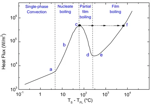
classical sketch of the heat flux transferred from the heating surface to the fluid versus the temperature difference between the surface and the bulk fluid temperature is shown in Figure 1.6 for pool boiling conditions. Several regions of heat transfer can be distinguished [63]:
0 – a: there is a little liquid superheat; heat transfer is by convection. Actually, in a flow boiling condition, as in BWR channels, forced single-phase flow occurs;
a – b: a few bubbles are formed but collapse after leaving the surface;
a – c: the number of bubbles increases rapidly – this is the nucleate boiling regime;
c: the boiling crisis is reached (see explanation in the next paragraph);
c – d: bubbles become so numerous that they begin to coalesce and clump near the heating surface (the vapour covering the surface acts as a heat insulator) – this is known as
transition boiling;
d – e: a continuous blanket of vapour forms over the heating surface – film boiling regime; e – f: thermal radiation from the surface comes into play – film and radiation regime.
f e d c b a Film boiling Partial film boiling Nucleate boiling Single-phase Convection 104 103 102 10 1 10-1 106 105 104 103 H e at F lu x ( W /m 2 ) TS - TFL (°C)
The “boiling crisis”, in which the clad surface temperature rises drastically, corresponds to a sudden drop in the heat transfer. It is know by several names including burnout, critical heat flux (CHF), dry-out and departure from nucleate boiling (DNB). Two types of phenomenon are of direct interest in nuclear reactor studies:
1 – Subcooled or low-quality CHF, identified as DNB: DNB can be caused by detachment of the bubble boundary layer. This type of DNB occurs in the PWR.
2 – High-quality CHF (dry-out): in this phenomenon, CHF occurs as the disruption of a liquid film that covers the heat transfer surface. CHF in the high-quality region will occur when liquid film “dries out”. This process is slow compared to subcooled DNB, since the high-velocity vapour core provides relatively good single-phase convection heat transfer. Dry-out is relevant in the BWRs.
In a flow two-phase mixture of liquid and vapour, the coolant flow becomes quite complicated. It is possible to distinguish several types of two-phase flow, as shown in the Figure 1.7. Some definitions can be introduced [63]:
Static quality ≡ χs ≡ (mass of vapour in mixture) / (total mass or mixture)
Void Fraction ≡ α ≡ (volume of vapour in mixture) / (total volume of liquid-vapour mixture)
Both parameters can be related as:
⎟ ⎠ ⎞ ⎜ ⎝ ⎛ − + = α α ρ ρ χ 1 1 1 g l s
In Figure 1.8, the void fraction is given for water at various static qualities and pressures [63]. Introducing the contribution of the different flow velocities, the flow quality can be written as:
S g l 1 1 1 1 ⎟ ⎠ ⎞ ⎜ ⎝ ⎛ − + = α α ρ ρ χ ,
Fig. 1.7. Flow patterns in a heated channel.
1.2.4. Relevant BWR transients
Despite the obvious need for plant-specific Probabilistic Safety Assessment (PSA), BWR transients of general interest can be identified and characterized in general terms. Transient scenarios, that involve considerable reactivity changes, are described, for example, in a recently issued NEA document [4]. The following events have been identified:
Overpressurisation events.
Large Break Loss of Coolant Accidents (LBLOCAs). Control rod withdrawal.
Feedwater temperature decrease.
Increase of core flow, main circulation pump flow rate increase. Anticipated Transient Without Scram (ATWS).
Core instability events.
These events are being described in summary in the next sections. 1.2.4.1. Overpressurisation
Overpressurisation events, caused by turbine trip without condenser bypass available and main steam line isolation valve (MSIV) closure, are shortly described hereafter.
The turbine trip (TT) event without condenser bypass available is a relatively frequent event in BWR operation. Due to the rapid closure of the turbine isolation valve a positive pressure wave propagates from the turbine valve to the reactor pressure vessel (RPV) and reaches the core from the top (across the dryer and steam separator deck) and from the bottom (across the downcomer and the lower plenum).
Core void collapse causes positive reactivity insertion and the associated power excursion is typically mitigated by scram initiation. The possible opening of steam relief valves to the containment wetwell pool counteracts the effect of the pressure increase in the RPV, but the short-term pressure wave propagation still influences the immediate core reactivity.
The MSIV closure event will include the rapid closure of one or several main steam line isolation valves. This closure creates in the short term a pressure peak (a similar situation to the turbine trip event) that causes void collapse in the core with associated reactivity increase. Opening of steam relief valves to the containment wetwell pool counteracts the effect of the long-term pressure increase in the RPV but the short-term pressure wave propagation will nevertheless influence the immediate core reactivity response. Closure of an
isolation valve in one steam line results in increased flow rate in the remaining steam lines, possibly causing several of the associated valves to close, thus resulting in a successive closure of a number of valves with an associated influence on the core reactivity.
1.2.4.2. LBLOCA
The Large Break Loss of Coolant Accident (LBLOCA) is a Design Basis Accident (DBA) for BWRs with external recirculation lines. The accident originates through the rupture of one recirculation line resulting in a 200% guillotine break. It is a basis for the Emergency Core Cooling System (ECCS) design as well as the design of the containment pressure-suppression system. From a reactivity point of view, the fast depressurisation will quickly increase the core void contents with an associated decrease in core power due to the reactivity feedback. The voiding and the immediately initiated shutdown system will quickly terminate the core fission power, thus resulting in the decay heat and the possible cladding metal-water reaction heat as being the remaining sources of core power.
The steam line break is similarly a DBA for many BWRs with internal MCPs and jet pumps. Nozzles located in the steam dome outlet connections to the steam lines limit the associated steam flow rate. A single steam line break, depending on the design, will also result in an increased flow rate in parallel steam lines due to connections with common headers. Despite these design characteristics, quite different flow rates will usually develop in the two ends of the 200% guillotine break due to the very different lengths of the flow paths.
1.2.4.3. Control Rod Withdrawal
The main function of the control rods in a reactor is to control core reactivity. However, as the control elements are inserted or withdrawn, they will also strongly affect the overall flux distribution and hence the power distribution of the reactor core [63].
The unintentional Control Rod (CR) withdrawal event is generally characterised by a single rod withdrawal from a core position with high reactivity worth, but as the reactivity control usually involves the manoeuvring of control rod banks other configurations can be conceived. Fast rod withdrawal can also be envisioned, during which a control rod is detached from its drive and thus remains fixed in the core while the drive is progressing downwards out of the core. The control rod thereafter may loosen and fall out of the core with an associated rapid reactivity increase.
The core design must be such that the shutdown margin is at least 1% with the highest reactivity worth control rod withdrawn from the core. Equally, the shutdown to cold condition
should always be possible even if one control rod group is assumed not to function. It should further be noted that compensation for the higher core initial reactivity (in a fresh or newly reloaded core) is not only accomplished by adequate control rod insertion but also by using burnable absorbers in the fuel itself.
1.2.4.4. Feedwater Temperature Decrease
The feedwater (FW) temperature decrease event can have its origin in malfunctions of FW pre-heaters and in a loss of pre-heater functionality. The latter occurs, for instance, at turbine trip, in which case the extraction of steam from the turbine stages to the pre-heaters is no longer available. Normally the FW temperature is about 180 – 220 °C when entering the RPV and a reduction of the temperature will increase the subcooling at the core inlet, which increases the reactivity.
Adjustments of the feedwater temperature (decrease) can be used as a mean to increase the core power at the end of a core cycle when the core condition includes maximum core coolant flow with all the control rods withdrawn (coast-down operation). However, a decrease in the feedwater temperature will result in a somewhat lower overall efficiency despite the increase in the generator electrical power.
1.2.4.5. Main Circulation Pump Flow Rate Increase
Normally, the core power is controlled by the core flow rate and thus by the MCP speed (at a given control rod pattern). An unintentional MCP flow rate increase may be caused by malfunction of possible valves installed in the MCP lines or by a spurious signal controlling the pump speed (power control mode), whatever is realistic for the concerned NPP. The case of start-up of a MCP at an incorrect temperature can also be conceived. Uneven distribution of the core inlet flow rate can be envisioned, resulting in uneven power distribution in the affected fuel assemblies.
1.2.4.6. Anticipated Transient Without Scram (ATWS)
The shutdown system is assumed to bring the core condition to a safe zero power condition with only the core decay heat remaining as a power source. However, the transients can be combined with a low-probability ATWS condition with a prerequisite of a certain degree of shutdown system failure. In relation to core reactivity insertion, this means that the reactivity effects from Doppler (fuel temperature) and coolant temperature and density (void) will have a predominant influence on the transient scenario. Operator actions can be expected
to mitigate the severity of the final consequences of the transients, but this cannot be accounted for in the short term. In a BWR, there are always other means to control the core power, though such methods are slower in response than the scram system, for example adjusting the MCP speed and the feedwater temperature and flow, and increasing the boron concentration in the coolant.
1.2.4.7. Core Instability Events
After a perturbation, if the system returns to the original steady state, then the system is considered stable. However, if the system continues to oscillate with the same amplitude, then the system is neutrally stable. If the system stabilizes to a new steady state or oscillates with increasing amplitude then the system is considered as unstable. For almost all cases of instability, the amplitude of the oscillations is limited by nonlinearities of the system and oscillations (which may be chaotic or periodic as in the case of limit cycles) are eventually established. The time series of the limit cycle oscillations may exhibit characteristics similar to the neutrally stable condition. Further, even in the steady state case, especially for two-phase systems with slug flow, small amplitude oscillations are visible. Thus, for identification purposes especially during experiments, often it becomes necessary to quantify the amplitude of oscillations as a certain percentage of the steady state value. Amplitudes greater than 10% of the mean value is often considered as an indication of instability [3].
Core instability transients usually originate at reactor operation with comparatively low power and low recirculation flow rate resulting in operation points being in the “exclusion region” (left upper corner) of the BWR core power-flow map. This type of event will be described with greater detail in the section 1.2.6.
1.2.5. Power and Flow Instabilities in BWRs
In the BWR, we can consider three types of instabilities [6] as follows:
1) Plant Instability – It is connected with both the control system and the way in which the plant reacts to external perturbations, as for example, in the case of a power request.
2) Instability by Reactivity – BWRs are closed systems, in which the reactivity is changed by the Doppler reactivity coefficient and the moderator density. Both coefficients are negative and because of this, the reactor is stable. The reactivity change as function of density is sufficiently strong to cause power oscillations after a perturbation. This occurs mainly when the reactor operates in low flow conditions, as in the case of natural circulation.
3) Thermal-hydraulic Instability – This type of instability is connected with two-phase flow characteristics in the heated channels. The flow oscillations are possible to appear in a particular channel groups and, in general, have not a global nature. Because of this, they are called local instabilities.
The second and third type of instabilities will be described in greater detail in the two next sections.
1.2.5.1. BWR Power Instabilities
BWR instabilities occur when an operating condition becomes unstable due some change in system parameters. Consequently, state variables identifying the reactor working conditions are observed to oscillate in different ways depending of the modalities of the departure from the stable operating point.
Power oscillations can have, for large amplitudes, an unwanted influence on the fuel integrity. In the fuel temperature limitation, it is essential to prevent exceeding the melting
point (3073.15 K for UO2). Fuel elements subjected to temperatures sufficiently high to
induce centreline melting will experience a significantly higher probability of failure (loss in the functional behaviour caused by change in physical properties). Furthermore, the low thermal conductivity of ceramic fuels leads to high temperature gradients that can cause fuel cracking and swelling [63].
From the point of view of the BWR safety, the most important type of power instability is the reactivity oscillations excited by thermal-hydraulic mechanisms. Two types of instability by reactivity have been characterized:
1) in-phase (core-wide): in this case, all the variables (power, mass flow, pressure,
etc) oscillate in phase determining a limit cycle; from the point of view of safety, this type of instability has relatively small relevance, unless it is associated with an ATWS (Anticipated Transient Without Scram);
2) out-of-phase: in this case, the instabilities occur when a neutronic azimuthal
mode is excited by thermal-hydraulic mechanisms, causing asymmetric power oscillations; at a given time, while part of the reactor presents high mass flow and low power level, in another part the opposite happens; this behaviour must be studied in detail because of safety implications.
During out-of-phase instabilities, power oscillates so that average power could remain essentially constant. The safety systems in a BWR scram the reactor according with received
average power signals and then large-amplitude out-of-phase oscillations could be established in the core without resulting in an automatic scram.
Out-of-phase oscillations in parallel channels do not require changes in total inlet flows to maintain the pressure drop across the core constant in time and space. Then, if the flow increases in a part of reactor, it decreases in a similar way in the other and the total flow remains nearly unchanged. This mechanism has the effect of increasing the gain of the thermal-hydraulic component in the BWR dynamics feedback, thus decreasing the reactor stability.
March-Leuba has studied the BWR instability phenomenon [10, 11] and presented a scheme [10] that clearly explains the out-of-phase mechanism (Figure 1.9). In the figure, the arrows represent the flow intensity through the core channels during an oscillation of period T. Case a is the fundamental (core-wide) mode of oscillation for which the whole core behaves almost uniformly. In the out-of-phase mode (case b), a constant core pressure drop and total recirculation loop flow is maintained by readjusting individual channel flows. This mode is also known as azimuthal mode.
Fig. 1.9. Case a – Core-wide instability – Pressure drop and average void oscillate. Case b – Out-of-phase instability – pressure drop and average void fraction remain essentially constant.
There are two effects in out-of-phase oscillations: on one side, the neutronics component is subcritical and tends to damp out oscillations; on the other side, the thermal-hydraulic component has greater gain than in the fundamental mode and tends to destabilize it. The relative importance of these two effects depends on the degree of subcriticality of the out-of-phase neutronic mode and on thermal-hydraulic parameters.
1.2.5.2. BWR Flow Instabilities
For a two-phase natural circulation loop, the heat input and its removal induces a large volumetric change that can carry the system to instable behaviour. One of the most important phenomena in a natural circulation loop is the density wave oscillation (DWO) which could affect the safe operation of the system, causing problems as mechanical vibration and thermal fatigue of components.
DWO can be categorised into two types: type 1 is the DWO under a nearly zero equilibrium quality condition, governed by gravitational pressure drop; type 2 is the one under high quality condition, governed by frictional pressure drop [49]. It is important to determine the stable operating regimes in the parameter space in nuclear systems with mathematical analyses. Since nonlinear terms are neglected, the linear analysis is only suitable for situations with small perturbations [43].
Ambrosini et al. [44] have studied the use of linear and nonlinear analysis tools to investigate the mechanism of density wave oscillations in boiling channels with uniform and constant heat flux showing the complexity of behaviour also in simple configurations.
Moreover, experimental investigations have been carried out to investigate the DWO phenomenon and its consequences in boiling channels, as for example in [45].
1.2.6. BWR – Power/Flow Map
The current trend of increasing reactor powers and of applying natural circulation core cooling has brought consequences for the stability of new BWR designs. These modifications have allowed BWRs to work at high nominal power, but they have also favoured an increase in the reactivity feedback resulting in a lower stability margin when the reactor is operated at low mass flow and high nominal power. Therefore, the increase in core size has led to a weaker spatial coupling of neutronic processes, which results in a stronger susceptibility to out-of-phase oscillations. In comparison to the situation in the seventies, the region of the power-flow map which has to be avoided grew to a respectable size.
Figure 1.10 shows an example of power-flow map for the Leibstadt NPP. The lower right side of the plot marks the allowed operating region, the grey region can only be entered if special measures are taken and finally, the black regime is forbidden due to stability concerns [5].
Conditions corresponding to about 50% core nominal power and 30% core inlet flow rate may be seen as the area in the power-flow map where the highest probability of oscillations occurs. The operation in this area is avoided by means of adequately defined control and trip conditions illustrated as additional “border lines” in the map. Nevertheless, certain perturbed transient conditions can still result in time windows in which operation in this area will occur, usually accompanied with the observation of oscillating core behaviour. The core two-phase flow itself provides a potential for oscillatory behaviour and the strong feedback between moderator coolant density and core power enhances the effect under certain conditions. In-phase and out-of-phase power oscillations have been actually observed and both modes for large amplitudes can have an unwanted influence on the fuel integrity. Control systems for the RPV pressure and downcomer level can influence the oscillatory behaviour in unfavourable way.
Fig. 1.10. Instability region in the power-flow map for the Leibstadt NPP.
The additional occurrence of an ATWS condition can be considered as an extreme event in screening analyses. Although this condition is beyond the DBA boundaries due to the low probability of occurrence, analysis results can provide valuable insights and be useful to designers and to safety analysts to optimise the Emergency Operating Procedure (EOP) and to better understand the safety margins of the NPP.
1.2.7. Inadvertent and Induced BWR Instabilities
Some of the several occurred instability events in BWR plants were inadvertent and other ones were induced intentionally as experiments. These instabilities were identified as periodic oscillations of the neutron flux via instrumentation readings. Essentially, neutronic power signals from Local Power Range Monitors (LPRM) and Average Power Range Monitors (APRM) have been used to detect and study the power oscillations. LPRM detectors give information about local neutron flux, and belong to the local power surveillance system. APRM detectors belong to the average power surveillance system, and use various LPRM signals to obtain the average power in a given reactor core level. In the two next sections, some inadvertent and induced instability events will be chronologically described.
1.2.7.1. Inadvertent BWR Instabilities
One of the inadvertent instability events happened in LaSalle NPP, in 1988. During a routine surveillance test, an instrument technician inadvertently caused the automatic shut-down of both recirculation pumps. As a consequence, the core flow rate was rapidly reduced from 76% to 29% of the rated value, corresponding to natural circulation conditions; this, in turn, led to the isolation of some of the steam extraction lines leading to the pre-heaters. The result of this action was a colder FW supply to the core. Between four and five minutes after the pump trip, the operators observed power oscillations with amplitude range from 25% to 50% of the rated value. The reactor scram occurred automatically on high neutron flux at 118% of rated power at about 7 minutes after the pumps tripped. This accident was analysed in many works, as in [12] and [13], for example.
In 1995, in Laguna Verde BWR/5, an instability event occurred during the start-up process. At the beginning, the power was 34% and slightly decreasing. The operator increased the coolant flow to stabilise the power level; then, the neutron population began oscillating and the core became unstable. The power began oscillating with growing amplitude reaching the maximum swing of 10% and then the operator scrammed the reactor by inserting control rods. The analysis of neutron noise showed that the transition from stability to instability is a gradual process that can be stopped by an earlier alarm indication [7]. No damage to the plant was reported.
In addition, the Oskarshamn-3 BWR experienced power oscillations in February 1998. The reactor power oscillated with high amplitude during two periods, between 200 and 300 s, and just before the scram occurred. A review of the possible causes suggested that the oscillations resulted from the particular used control rod sequence and the power distribution obtained as a result [22].
In November 2001, an in-phase neutron flux oscillation occurred at Philippsburg-1 NPP after a FW temperature transient. A similar event occurred at the Swedish BWR Oskarshamn-2 in February 1999. In both events, a scram terminated the neutron flux oscillation, but only at the fixed scram set point at 120% and 132% power level, respectively. In both cases, control rod insertion was activated too late to limit the oscillations effectively before reaching the scram set points [61].
After the first instability events, authorities in all Countries required a review of the stability features of their BWRs. The authorities include the requirements of analyses in the safety analysis reports and changes in the procedures and plant safety systems. The major safety concern associated with instability is the cooling of the fuel and cladding integrity.
Consequently, the main objectives of BWR stability analyses could be summarized as follows [35]:
to assess the stability margins in the reactor plant, including normal and off-normal conditions;
to predict the transient behaviour of the reactor, should an unstable condition occur;
to help in designing and assessing the effectiveness of countermeasures adopted to prevent and mitigate the consequences of instabilities.
1.2.7.2. Induced BWR Instabilities
Turbine trip and stability tests were conducted in the Peach Bottom 2 BWR in 1977. The stability tests were done along the low-flow end of the rated power-flow line, and along the power-flow line corresponding to a minimum recirculation pump speed [42]. The main objective of these tests was to provide a database for the qualification of transient design methods used for reactor analyses at operating conditions. These data are being used in this thesis to validate the RELAP5/PARCS coupled codes in the predictions of instabilities. Then, the Peach Bottom instability tests will be described in greater detail in Chapter 2.
A stability test was performed at Forsmark-1 BWR on January, 1989, during start-up operation after the scram due a turbine trip. In total, 36 signals including those from APRM and LPRM, total core flow, local channel flows were recorded on a digital computer. These data were useful to the validation of analysis techniques as verified, for example, in the reference [48].
In 1990, a stability test was conducted in the BWR Leibstadt, to test the ability of the monitoring system to cope with demanding operation situations; the power oscillations were transformed from the in-phase mode into the out-of-phase mode, by the withdrawal of some control rods. After 660 seconds from the test beginning, an unstable oscillation started. Two opposite LPRM signals demonstrated that the oscillation was out-of-phase. At approximately 740 seconds, the maximal oscillation amplitude was reached and the oscillation was suppressed by decreasing the power [53].
The NACUSP project, started in December 2000, investigates natural circulation and stability performance of BWRs. One of its main aims is understanding the physics of the phenomena involved during the start-up phase of natural-circulation-cooled BWRs, providing a large experimental database and validating state-of-the-art thermo-hydraulic codes in the low-pressure, low-power operational region of these reactors [8].
Three experimental facilities within the NACUSP project have yielded a large, unique database. Natural-circulation and stability characteristics at nominal pressure were collected from extensive experiments at the DESIRE facility. Low-pressure characteristics were measured at the PANDA (large scale) and the CIRCUS (CIRculation Under Start-up) small-scale facility [8]. PANDA and CIRCUS have been used for a variety of thermal hydraulic tests including investigations of instabilities at low pressure and low flow during the start-up phase of a natural-circulation BWR. During the start-up, so-called flashing-induced instabilities can arise. Under specific conditions, the feedback between void generation in the riser and buoyancy of the natural-circulation loop may give rise to flow oscillations [14, 15]. The term “flashing” refers to the occurrence of boiling in a natural circulation BWR, due to the decrease of hydrostatic pressure and saturation enthalpy along the flow path, when the coolant flows upwards through the core and riser sections. Since the saturation enthalpy is strongly dependent on the pressure at pressures lower than 20 bar, the influence of flashing becomes especially important under low-pressure conditions.
The experimental facility DESIRE is a scaled natural-circulation loop designed after the Dodewaard circulation BWR. It simulates one fuel assembly of the natural-circulation loop of the Dodewaard BWR with Freon-12 as scaling fluid. By systematically performing experiments in the whole operating range of the natural-circulation Freon-12 facility DESIRE, a stability boundary has been determined for a specific configuration. A large amount of data was gathered to be used for future benchmarking of computer codes [9].
1.2.8. Methods and Tools to Study BWR Instabilities
To study instabilities in BWRs, many numerical models and computer codes have been developed. The methods have been validated using data provided by signals of several experimental tests and by inadvertent events. The good agreement found between computational analyses and the experimental available data contributed to better understanding the BWR instability phenomena.
1.2.8.1. Mathematical Models
Many literature works are related to numerical methods to study the BWR instabilities. Several authors use the modal method to investigate the phenomena, as in [10, 16, 17, 18, 19, 20, 21, 30] for example. The modal analysis is a process conceived to determine the dynamic characteristics of a system, in the form of natural frequencies, decay factors and oscillating
modes. This information is used to formulate a mathematical model of the dynamic behaviour of the system, denominated as “modal model” [20].
The Decay Ratio (DR) and the natural frequency (NF) of the oscillations are typical parameters used to evaluate the instabilities. In the section 1.2.9, some basic definitions of DR will be described. Other parameters can also to provide valuable information, such as the Lyapunov exponents associated to the time series. In fact, the Lyapunov exponents are also used as a measure of the stability of the neutronic time series [6, 66].
Morishima [38] presents a methodology to explain the mechanism of BWR core-wide stability in terms of characteristics poles of the closed-loop transfer functions for reactivity and core-flow inputs. Among the poles, those originating from the void dynamics are essential in characterizing the core-wide power oscillations and their explicit expressions show the connection between channel thermal-hydraulics and core-wide stability. The methodology was applied to Ringhals BWR stability signals and the results for DR and NF were compared with those in the benchmark [36] obtaining good agreement.
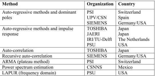
Different time series analysis methods that can be applied in the study of BWR stability were used and compared utilizing data provided from the Forsmark 1 & 2 Stability Benchmark [39]. The activity was focused on the analysis of time series data by means of noise analysis techniques in the time domain. Several cases were studied as, for example, the importance of the time duration of measured data, APRM data containing more than one natural frequency of the core, data with a mixture between a global oscillation mode and a regional (half core) oscillation, and others. Table 1.2 presents the several methods used by the participants to obtain results to DR and NF.
Tab. 1.2. Participants and methods used in the Forsmark Stability Benchmark.
Method Organization Country
Auto-regressive methods and dominant poles PSI UPV/CSN SIEMENS Switzerland Spain Germany/USA Auto-regressive methods and impulse
response TOSHIBA JAERI IRI/TU-Delft PSU Japan Japan The Netherlands USA
Auto-correlation TOSHIBA Japan
Recursive auto-correlation SIEMENS Germany/USA
ARMA (plateau method) PSI Switzerland
Power spectrum estimation CSNNS Mexico
Some of the conclusions reached from this joint study were the following [39]:
Concerning the time duration of the signal in estimating the DR: “the duration depends on the value of DR (roughly inversely proportional to it). For power spectral density between 4,000 and 10,000 points are required for auto-regressive methods”.
About the reactor stability margin: “the real margin should be determined on power. Frequency domain codes can determine it; they are efficient but not sufficient. The DR is a measure of linear stability and should therefore not be used as the only indicator of BWR stability”.
About the possibility to determine the DR of an out-of-phase oscillation: “this is possible for DR up to 0.7 ± 0.1 and only if enough LPRM signals per plane are provided. Because there are many ways of doing it wrong and only a few to do it right, it depends on the expertise of the analyst, or on the sophistication of the monitoring algorithm”.
In this thesis, two programs developed in the University of Pisa will be used to calculate the DR and NF from BWR power instabilities: the Analysis of Decay Ratio Instability (ADRI) program [40] and a program called DRAT, that will be described in the sections 3.2.1 and 3.2.2 of the Chapter 3, respectively.
1.2.8.2 Computer System Codes
Computer programs developed for the modelling and the transient simulation of a complete nuclear power plant with a high degree of detail are called system codes. Different choices are adopted for neutron kinetics and two-phase flow modelling. The application of thermal-hydraulics (TH) and neutron kinetics (NK) codes to LWR analyses was exhaustively
discussed in the three volumes edited by the project CRISSUE-S1 [4, 53, 54]. Specifically, the
project CRISSUE-S treated the interactions between neutron kinetics and thermal-hydraulics that affect neutron moderation and influence the accident performance of the NPPs.
Therefore, descriptions of TH and NK codes will be shortly treated here in the two next sections, focusing the attention on the current methodologies of coupling codes technique in section 1.2.8.2.3.
1The acronym for the CRISSUE-S project is Critical Issues in Nuclear Reactor Technology: A State-of-the-art Report.
1.2.8.2.1 Thermal-Hydraulic Codes
The evaluation and assessment of the safety of NPPs is closely related to the ability to determine the temporal and spatial distributions of the flow TH conditions along with associated effects from heat sources and heat sinks throughout the reactor coolant system, and especially in the core region.
The TH system analysis codes, (for example, RELAP5, TRAC-BF1, COBRA-TF) are useful tools that can be applied for NPP safety analyses and evaluations of plant responses to specified process disturbances. The accumulated experiences from an ever-growing amount of analyses provide comprehensive guidance for the use of the codes. However, there are still areas of code applications that reveal limited experience, as in transients in which pressure wave propagation effects are important and for which extensive 3D and recirculating flow formation occur in certain parts of a system. These kinds of flow conditions can have a great influence on the course of transients, also in relation to core reactivity response; therefore, it can be essential to have an accurate simulation of the flow field distribution at the core inlet.
1.2.8.2.2 Neutronic Codes
For neutron kinetics, both 1D and 3D models are available. Obviously, if the interest is to analyse regional oscillation phenomena, a 3D neutron kinetics model is essential. Normally, the neutron kinetics calculation is performed in a two-step procedure; in the first step, adequate nuclear cross-sections for specified fuel types and core compositions are provided in a form that can be directly used in the second step. The cross-sections are generally obtained solving the integral Boltzmann neutron transport equation for individual fuel assemblies, including the neutron energy-dependent probabilities for the neutron reactions in various isotopes [4].
The results from these calculations include homogenised few-group nodal cross-sections and related data, including neutron kinetics data, which can be used in the second step of the calculation procedure. In this second step, the transient multi-group 3D diffusion equations are solved to provide the nodal neutron flux distribution in the complete reactor core, or half core or quarter symmetry, and associated spatial core power distribution. This is accomplished using nodal diffusion codes, examples of which include PARCS and SIMULATE-3.
1.2.8.2.3 Coupling between Thermal-Hydraulic System and 3D Neutronic Codes
Nowadays, the nuclear industry and the scientific community turned their attention to the development of coupled 3D neutron kinetics (NK) / thermal-hydraulic (TH) system codes to investigate BWR instabilities, in particular, the regional (out-of-phase) type. The coupled system codes can model accurately not only reactivity-initiated accidents (RIA), but also typical reactor operational transients as turbine trip. These programs are often called “best-estimate” analysis tools and describe, in a more realistic way, the local core effects and coupled reactor core/plant dynamics interactions.
Two different approaches are generally utilised to couple TH system codes with 3D neutronic kinetics models: serial integration and parallel processing coupling. The serial integration approach includes modification of the codes, usually by implementing a neutronic section (i.e. subroutines, functions) into the TH system code. In the parallel processing approach the TH system and 3D NK codes are executed separately and exchange the needed data during the calculation. In the former case, a substantial programming effort is needed to properly achieve the integration, while in the latter case only minor modifications are made to already existing codes. In the latter case it is crucial to provide the data exchange between the two codes in carefully and properly selected time sequences; thus, great attention must be paid to the process of data transfer and the associated time control of the execution processes of the two codes.
The choice of a coupling technique can affect the numerical stability of the integrated code system. An important criterion to comply with in a hydrodynamic coupling is that the methodology must conserve mass and energy, as proposed in [23] by Weaver et al. They present a methodology that allows RELAP-3D to be used with other computer programs to perform integrated analyses of nuclear power reactor systems and related experimental facilities. The RELAP5-3D code is a fully integrated, multi-dimensional TH and NK system code. The methodology allows the coupling of the hydrodynamic solution of various computer programs in a manner that preserves mass and energy. The process accommodates the coupling of codes using different fluid models, that is, codes using different numbers of conservation equations to model fluid flow.
The coupling between TRAC (TH code) and RAMONA (NK code) has been used widely for BWR transient and accident analyses with good results. López et al [28] propose a methodology for the coupling of RAMONA-3B and TRAC-BF1. In a direct-coupling, three PCs were used. One PC hosts an implementation of RAMONA and is used for modelling of the 3D core neutron kinetics. Another PC uses TRAC to model all major reactor internals
including hot, medium and peripheral core regions. A third PC runs a copy of the TRAC code and is used to model as many individual fuel bundles as possible, in order to provide TH conditions to the neutron core diffusion equation. It was observed that considerable “transients” might be introduced if the differences in the steady state TH results of these codes are not properly controlled during the initial coupling. Then, an indirect coupling of these codes was therefore proposed. Tests run an hypothetical transient with multiple rod motion. The test results indicate that the indirect coupling is more reliable, simpler and faster simulations are possible in this computer-distributed environment, under PVM (Parallel Virtual Machine) control.
The 3D neutronics capability in the TH system code is usually obtained through the external coupling between the system code and an adequate transient 3D kinetics code, and it is explicit in the time domain. An obvious advantage of this methodology is that the codes are isolated and can be independently updated and maintained. The kinetics model receives TH data from the TH system code, such as fuel temperatures, coolant void fraction, phasic densities and temperatures, and boron concentration, and returns the fuel power back to the TH system code.
The temporal coupling among the codes is an important point to be considered during coupling calculations. In most cases, the frequency of 3D kinetics calculations can be optimized to speed up the calculation. For this purpose, Solìs et al [32] implemented a multiple time step marching scheme in TRAC-BF1/NEM calculation. NEM is a 3D neutron kinetics model, based on the nodal expansion method. The scheme allows TRAC-BF1 solution to march several steps while NEM only marched one large time step. In order to provide best-estimate analysis of local safety parameters, the COBRA-TF thermal-hydraulics sub-channel code was coupled to the BF1/NEM code using PVM. Since TRAC-BF1/NEM and COBRA-TF code use their own algorithm to select the time-step size during a given calculation, some techniques were implemented to have a good synchronization of the codes when marching on the same time scale.
The coupling of TH models with full 3D dynamics analytical tools allows for a full-integrated solution between the power production and the moderator and fuel temperature feedback effects. The technique has been applied to several types of reactors. For example, STAR (NK code) was coupled with 3D COBRA (TH code) to model transients in a TRIGA reactor [24]. The research validated the assumption that the PSU TRIGA provides sufficiently complex fluid flow conditions and kinetics detail for benchmark experiments that could be used to validate coupled TH/NK models.