2 Modelling of capillary forces
The most frequently cited effects of capillary forces are the influence on sticking during the releasing tasks, the negative effect on the reliability of microswitches that can collapse by capillary forces and the positive effect of surface tension when selected as gripping principle.
In this chapter a brief description of fundamental parameters and some approximations of the capillary force are presented.
2.1 Fundamental parameters: Surface Tension, Contact Angle, Laplace
Equation
Looking at soap bubbles (Figure 1) or small water drops, it is possible to observe that they have an elastic membrane, characterized by a surface tension that acts against their deformations.
a
b
Figure 1 Examples of surface tension effects: a soap bubble (a) (source [10]) and a water striders (b) (source [11])
As reported in [1], the classical explanation of this phenomenon is that, while all particles inside the liquid are attracted by their adjacent molecules, the molecules located at the interface between the liquid and, for example, a gas are subjected to a so called “attraction default” (Figure 2). From a thermodynamic point of view, the general shape of the liquid is the one that minimizes the interface area (minimum energy). From a mechanical point of view the surface tension is a tensile force by length unit (Nm-1).
Liquid surface
Figure 2 Illustration of the “attraction default” (source [1])
Surface tension γ is an important parameter in microassembly world because the force it generates decreases with the linear dimension while the volume forces (weight) decreases more quickly.
Referring to interface between different state of matter, it is possible to define interfacial tensions between liquid and vapour (γLV), between solid and liquid (γSL) and between solid and vapour (γSV). In particular, for a droplet placed on a solid substrate (Figure 3), the three previously mentioned interfaces are connected by a triple line called contact line. The three interfacial tensions are in balance.
Figure 3 Illustration of the Young-Dupré equation (source [1])
The liquid-vapour interface makes with the substrate an angle θ and it is called contact angle. In static conditions, interfacial tensions are linked by the Young-Dupré equation:
SV SL
LV θ γ γ
γ cos + = (2.1)
Being the state of equilibrium, the pressure difference across the liquid-vapour interface has to equilibrate the surface tension. For example, inside a soap bubble the pressure is bigger than the outside pressure to overcome the tension effect. Generally, the Laplace equation links the pressure difference with the curvature of the interface. The Laplace equation is obtained as reported in [1].
A surface element dS of a curved surface S at equilibrium with the coordinate curves that intersect one another with an angle of 90° has been considered (Figure 4).
pin
pout
Figure 4 Surface element of an interface between a liquid and a gas (source [1])
Considering only the components along the normal to the surface element, the forces acting on the surface element are the forces exerted by the internal and external pressure on dS , and the force exerted by the surface tension γ along the lines of the perimeter. The component along the normal to the surface element of the force exerted by the surface tension along the lines v and v+dv is (refer to Figure 5) :
2 sin 2γ dθ1 dv (2.2) 2 1 θ d 2 1 θ d
Figure 5 Detail of the surface tension acting along v and v+dv (source [1])
A Similar equation can be written for the force along the lines u and u+du :
2 sin
2γ dθ2
The balance of the forces is: dS p dS p d dv d du + + out = in 2 sin 2 2 sin 2γ θ2 γ θ1 (2.4)
Using the definitions:
dv du
dS = ; du= R2dθ1 ; dv=R1dθ2 (2.5) and the classical approximation for small angles sinx≈x , the balance can be rewritten:
out in p p R R = − + 2 1 1 1 γ (2.6)
Remembering the definition of mean surface curvature H : + = 2 1 1 1 2 R R H (2.7)
the balance can finally be rewritten into the Laplace equation:
out in p p H = − γ 2 (2.8)
Two solids linked by a liquid bridge, also called meniscus, are now considered. Let us call the upper solid the “tool” or the “gripper” and the lower one as the “object”. Assuming axial symmetry, Figure 6 the contact line between the meniscus and the object is a circle with radius r1 , while the contact line between the tool and the meniscus is a circle with radius
r2. The pressure inside the meniscus is pin and the pressure outside is pout. z represents
the separation distance between the gripper and the object.
The Laplace force, due to the pressure difference pin-pout and acting over the area
π
r
1 2, and the tension force, exerted by the surface tension along the contact line, act on the object.
Figure 7 Origin of the Laplace force (source [1])
According to Figure 7 and using equation (2.8), the Laplace force FL is: 2
1
2 H r
FL = γ π (2.9)
Figure 8 Origin of the tension force (source [1])
The tension force FT depending on the surface tension γ , acting along the contact circle
and projected on the vertical direction, according to Figure 8, is:
(
1 1)
1 sin
2π γ θ +φ
= r
FT (2.10)
These two forces constitute what we call the capillary force FC that is given by:
(
)
2 1 1 1 1 sin 2 2 r H r F F FC = T + L = π γ θ +φ + γ π (2.11)2.2 State of the art on the approximations of the capillary force
Capillary force can be calculated if the geometry of the liquid bridge is known, but some approximations can be used in order to valuate the force more quickly. Most often the capillary forces are approximated by several formulations that all include the following assumptions:
o axial symmetry of the liquid bridge
o gravity effects on the meniscus shape are neglected
According to [1] the main approaches to approximation are the energetic approach and the geometric one.
2.2.1 Energetic approach
This method consist in:
2 writing the interfacial energy of the system as a function of the parameters of the geometry of the system;
2 deriving this energy with respect to one of the parameters (for example separation distance z) obtaining the capillary force as a function of this parameter;
2 estimating the derivates of the other parameters with respect to the previously chosen one by assuming a mathematical relation.
For the solution of this method additional assumptions, the most of it restrictive, have to be adopted. For example, calculating the interaction between two parallel plates (Figure 9), the suppositions to be done are:
o the volume of the meniscus remains constant (not restrictive), in order to calculate derivates;
o the separation distance z is small compared to the radii, so the term depending on the lateral area is negligible;
Figure 9 Energetic approach: geometry used the case of two parallel plates (source [1])
With these hypothesis, the force acting between two parallel plates can be written as:
) cos cos (12 θ1 22 θ2 πγ r r z F =− + (2.12)
If the lateral area is taken in consideration, the meniscus shape can be approximated by a cylinder and the force can be rewritten as:
) cos ( 2 2 z r r z F =− πγ θ + (2.13)
Using other assumptions and neglecting the contribution of lateral area, it is possible to calculate the force between a sphere and a plane with the equation:
1 cos 4 + − = h z R F π γ θ (2.14)
The detailed explanations of these equations are reported in [1].
2.2.2 Geometrical approach
Frequently in the literature the approximation of the meniscus to an arc is used to calculate capillary force. This method requires:
2 the determination of five parameters of the geometry of the meniscus (r0, z0, ρ, θmin,
θmax in Figure 10) using appropriate conditions;
2 computing the mean curvature of the meniscus at the neck and assuming constant volume and constant curvature (this is the largest approximation of this method because the assumed geometry cannot have constant curvature);
Figure 10 Geometrical approach: circle approximation of the meniscus between two parallel plates (source [1])
With this method, in the case of two parallel plates, the capillary force can be written as:
( )
2 1 1 1 sin 2 2 r H r F = π γ θ + γ π (2.15)( )
+ − = ρ ρ γ π θ γ π 1 ' 1 sin 2 r1 1 r12 (2.16)In some cases a parabolic approximation of the meniscus is used when the circle approximation leads to numerical difficulties (degeneration of the geometry). The meniscus is represented with the curve of equation:
c bz az z
r( )= 2 + + (2.17)
The three unknown a, b and c can be determined imposing some relations, the other two unknown can be determined by using an iterative scheme.
2.2.3 Geometrical approach with normalization
In the article [8] the authors use a modified geometrical approach and obtain an interesting plot of the normalized capillary force as a function of the distance d.
Figure 11 Geometry of the liquid bridge between a spherical object and a plate used in [8].
Figure 11 shows a model for the analysis of a liquid bridge between a spherical object and the plate. The following assumptions are required:
2 the influence of gravity is negligible, i.e. the Bond number (gL2∆ρ/γ, where g is the local acceleration due to gravity, ∆ρ the density difference between the fluids on either side of the interface, and L some characteristic length for the system) is sufficiently small; 2 the dynamic flow of the liquid is negligible;
2 the volume of the liquid V is conserved;
2 the contact angles are determined by Young’s equation; 2 the object and the plate are rigid;
2 the area of the plate is infinite; Considering the Laplace equation:
out in p p H = − γ 2 (2.8)
it is possible to affirm that the mean curvature H is a constant, being a constant both the pressure difference (pin-pout) and the surface tension γ . The value of H in can be
expressed with geometrical parameters as
(
)
2 32(
)
2 12 2 2 1 1 2 + + + = dX dZ X dX dZ dX dZ dX Z d H (2.18)Using the following normalizations: R Z z = ; R X x= ; R D d = ; γ πR F f = ; 3 R V v=
the equation (2.18) becomes:
(
)
x dx d HR sinε sinε 2 = + (2.19)where e is the angle between the normal to the meniscus and the vertical axis.
In the end, two expression are written, one for the normalized distance and one for the normalized capillary force:
) cos 1 ( 1− − ϕ = z d (2.20)
(
)
[
ϕ θ ϕ 2ϕ]
1 sin sin sin 2 HR f = + − (2.21)Figure 12 Capillary force curves (θ1 =θ2 =60?): (i) v =0.1, (ii) v =1.0, (iii) v =50.0,(iv) v =100.0 . (source [8])
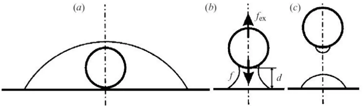
Figure 13 Schematic illustration of the liquid profile and the definition of the distance d, the capillary force f, and the external force fex: (a) the object is fully covered with the liquid; (b) the liquid bridge; (c) after collapse of the
The solid lines in Figure 12 show the capillary force f as a function of the distance d for different values of v and θ1 =θ2 =60°. The broken lines obtained from (2.19), (2.20), and (2.21) are the imaginary solution of the present problem. Each curve exhibits the different features of the liquid bridge: (i) The capillary force is always attractive, and the value of f decreases with d. (ii) The capillary force is always attractive, and f has a maximum value. (iii) The capillary force is repulsive for d =0, and f has a maximum value, and is zero at a certain point. (iv) The liquid bridge cannot exist for d =0. In this case, the object is fully covered with the liquid, as shown in Figure 13(a). The capillary force is repulsive for the minimum d, and f reaches a minimum and then increases with d until reaching a maximum value. The value of f is zero at a certain point. When f =0, the object floats on the liquid; such floating can be observed in cases (iii) and (iv).
2.2.4 Pendant drop
According to [9] and others, the simplest way to realize a drop is to allow liquid to flow slowly from the lower end of a vertical tube of small diameter (Figure 14). When the pendant drop exceeds a certain size it is no longer stable and detaches itself. The mass m (or weight mg) of the largest drop that can hang from the end of a tube of radius a can be found from the formula:
α γ π cos 3 a
mg = (2.22)
where γ is the surface tension of the liquid, α is the contact angle with the tube, g is the acceleration due to gravity. This relationship is the basis of a convenient method of measuring surface tension, commonly used in the petroleum industry.
![Figure 1 Examples of surface tension effects: a soap bubble (a) (source [10]) and a water striders (b) (source [11])](https://thumb-eu.123doks.com/thumbv2/123dokorg/7336074.91367/1.892.173.726.662.873/figure-examples-surface-tension-effects-bubble-source-striders.webp)
![Figure 2 Illustration of the “attraction default” (source [1])](https://thumb-eu.123doks.com/thumbv2/123dokorg/7336074.91367/2.892.297.591.102.241/figure-illustration-attraction-default-source.webp)
![Figure 4 Surface element of an interface between a liquid and a gas (source [1])](https://thumb-eu.123doks.com/thumbv2/123dokorg/7336074.91367/3.892.279.624.110.425/figure-surface-element-interface-liquid-gas-source.webp)
![Figure 6 Liquid bridge between two solids (source [1])](https://thumb-eu.123doks.com/thumbv2/123dokorg/7336074.91367/4.892.230.665.786.1094/figure-liquid-bridge-solids-source.webp)
![Figure 8 Origin of the tension force (source [1])](https://thumb-eu.123doks.com/thumbv2/123dokorg/7336074.91367/5.892.200.713.568.776/figure-origin-tension-force-source.webp)
![Figure 9 Energetic approach: geometry used the case of two parallel plates (source [1])](https://thumb-eu.123doks.com/thumbv2/123dokorg/7336074.91367/7.892.253.647.115.393/figure-energetic-approach-geometry-used-parallel-plates-source.webp)
![Figure 10 Geometrical approach: circle approximation of the meniscus between two parallel plates (source [1])](https://thumb-eu.123doks.com/thumbv2/123dokorg/7336074.91367/8.892.245.655.118.403/figure-geometrical-approach-circle-approximation-meniscus-parallel-plates.webp)
![Figure 11 Geometry of the liquid bridge between a spherical object and a plate used in [8]](https://thumb-eu.123doks.com/thumbv2/123dokorg/7336074.91367/9.892.349.546.247.523/figure-geometry-liquid-bridge-spherical-object-plate-used.webp)
![Figure 14 Pendant drop (source [9])](https://thumb-eu.123doks.com/thumbv2/123dokorg/7336074.91367/11.892.367.519.832.1085/figure-pendant-drop-source.webp)