RICERCA DI SISTEMA ELETTRICO
Rapporto preliminare del progetto del target di IFMIF comprensivo di
disegni, analisi numeriche e valutazione dei costi
D. Bernardi, M. Frisoni , G. Miccichè, T. Pinna, M.T. Porfiri, M.Serra
Agenzia nazionale per le nuove tecnologie, l’energia e lo sviluppo economico sostenibile
RAPPORTO PRELIMINARE DEL PROGETTO DEL TARGET DI IFMIF COMPRENSIVO DI DISEGNI, ANALISI NUMERICHE E VALUTAZIONE DEI COSTI
D. Bernardi, M. Frisoni, G. Miccichè, T. Pinna, M.T. Porfiri, M.Serra (ENEA) Settembre 2012
Report Ricerca di Sistema Elettrico
Accordo di Programma Ministero dello Sviluppo Economico - ENEA Area: Governo, gestione e sviluppo del sistema elettrico nazionale
Progetto: 1.3.2 Fusione nucleare: attività di fisica e tecnologia della fusione complementari a ITER Responsabile del Progetto: Aldo Pizzuto, ENEA
Index
Summary ... 4
Introduction ... 5
IFMIF TA Engineering Design Activities ... 6
Target Assembly design ... 7
Safety assessment of the Li Target Facility ... 12
Numerical analyses... 13
Nuclear calculation ... 13
Activation calculations for the Activated Corrosion Products (ACP) ... 13
Energy deposition of D beams in the Li jet for thermo-hydraulics calculations ... 17
Cost evaluation (rough) ... 19
Conclusions ... 20
References ... 20
Summary
The International Fusion Materials Irradiation Facility (IFMIF) is an international joint project aimed at developing an accelerator-based neutron irradiation facility to test and qualify candidate materials to be used in future fusion power reactors.
Within the current IFMIF Engineering Validation and Engineering Design Activities (EVEDA) phase, ENEA is involved in the design of the Target Assembly (TA) with removable bayonet Backplate which is one of the two alternative concepts envisaged for the TA system of IFMIF (the other being the Integral Target Assembly to be developed by JAEA in Japan).
In the present annual period covered by the current MSE-ENEA Agreement, the design of the Target Assembly with bayonet Backplate has advanced starting from a reference model based on the previous design which was described in the system Design Description Document of the Engineering Design Activities phase I (DDD-I).
In particular, the integration of the Target Assembly with bayonet Backplate into the Li loop and Target Test Cell models has been performed. Moreover, some important features previously not present in the model, such as the TA supporting structures and positioning system and the thermal compensating system were developed and introduced in the design.
As a further advancement, some work has been done on the numerical analyses in support to the TA design and the safety assessment of the IFMIF Lithium Target Facility that is also a task in charge of ENEA within the IMIF/EVEDA project. Regarding this latter activity, a contribution has been given to the preparation of the IFMIF main safety documents. Updated activation calculations for the Activated Corrosion Products (ACP) have been also performed in order to provide the radioactive inventories of Lithium containing ACP due to the irradiation of both neutron and deuteron fluxes.
Concerning the numerical analyses, the work performed has been mainly devoted to setting up the software tools (in particular the McCad interface software) to perform the neutronic analysis of the integrated TA model, that will be carried out in the next phase of the project. Calculations of the power deposition of Deuteron beams in the Lithium jet, which is needed for thermo-hydraulics calculations, have been also performed.
In the present document, a detailed description of all the above mentioned activities is reported. Moreover, a rough cost evaluation of the TA system with bayonet Backplate is also given.
Introduction
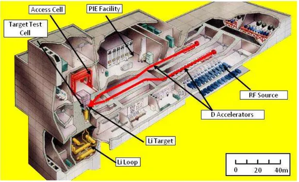
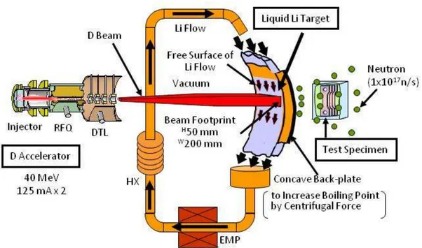
The International Fusion Materials Irradiation Facility (IFMIF) is an international joint project launched in the framework of the Broader Approach agreement between EU and Japan and aimed at developing an accelerator-based neutron irradiation facility to test and qualify candidate materials to be used in future fusion power reactors [1]. In particular, it will allow the development of a material irradiation database for the design of the future DEMO fusion plant. As shown in Fig. 1, IFMIF plant consists of Accelerator Facility (AF) including two sets of deuteron (D) accelerators and RF sources, Lithium Target Facility (LF) including a lithium (Li) target and a Li loop, Test Facilities (TF) including Target Test Cell (TTC) and Access Cell (AC), Post Irradiation Examination Facility (PIEF), and Conventional Facilities (CF).
As conceptually shown in Fig. 2, during beam operations, two deuteron (D) beams with a energy of 40 MeV and a total current up to 250 mA are injected on a liquid lithium (Li) target so that neutrons with typical energy of around 14 MeV simulating fusion condition are generated through D-Li reactions and test specimens are irradiated up to a damage rate of 20 dpa/y. The irradiated specimens are tested in the PIE Facility.
Fig. 1 - Conceptual view of IFMIF plant
In order to have a stable liquid lithium film, a target system, consisting in a Target Assembly (TA) properly integrated into a lithium loop, is conceived [2]. Within such concept, the TA is mainly devoted to house the beam footprint, to remove the 10 MW heat power released by the deuteron beams and to produce a stable lithium jet with a nominal speed of about 15 m/s.
Within the current IFMIF Engineering Validation and Engineering Design Activities (EVEDA) phase, ENEA is one of the European contributors to the design of the IFMIF machine under the technical and organizational coordination of European Union’s Joint Undertaking for ITER and the Development of Fusion Energy (Fusion for Energy, F4E) in the framework of the Broader Approach Agreement that was signed in 2007 between Europe and Japan.
In particular, ENEA is involved in the design of one of the two alternative concepts envisaged for the TA system of IFMIF. These two concepts include:
the integral TA (to be developed in Japan by JAEA);
the so-called removable bayonet back-plate concept (to be developed in Europe by ENEA)
The integral concept requires that, when the BP is too degraded, due to the effects of neutron irradiation and exposure to high velocity liquid metal flow, the whole TA, including the integrated back plate, is replaced. On the other hand, the replaceable concept foresees that only the back plate is replaced, while the rest of the target assembly, being less exposed to neutron irradiation, can survive for a longer time. Although technically more complex, this latter option has the advantage to limit the nuclear waste build-up and to make the replacement operations easier.
Fig. 2 - Concept of neutron generation in IFMIF Lithium Target
The TA with bayonet BP system consists of a fixed plate (called the interface frame) attached to the main structure of the TA, on which the removable back plate can be slid and then rigidly connected by means of suitable skate mechanisms and tightening bolts.
The present report describes the main activities carried out in the reference period concerning the engineering design of the IFMIF Target Assembly system with bayonet BP.
IFMIF TA Engineering Design Activities
The scope of the European Engineering Design Activities (EDAs) of IFMIF/EVEDA project is to deliver the Intermediate IFMIF Engineering Design Report (IIEDR) which will serve as main input document to allow starting the process for a project review leading to the next detailed design phases as well as the start of the process for a site selection for the IFMIF plant .
In this context, ENEA is committed to contribute to the IIEDR by providing the engineering design of the Target Assembly with bayonet Backplate. The whole workpackage is defined in the IFMIF Procurement Arrangement ED03-EU [3] that recently obtained the final formal approval by the IFMIF Project Team (PT).
In the following, a brief description of the technical work performed and of the results obtained in the present annual period covered by the current MSE-ENEA Agreement is reported. The work includes in particular the update of the TA design already started within the previous annual period of the MSE-ENEA Agreement [4], the contribution given so far on the safety assessment of the IFMIF Lithium Target Facility and the numerical analyses carried out in support to the design of the TA. A rough evaluation of the main cost sources of the TA system is also presented.
Target Assembly design
A reference model based on the previous TA design [4] included in the system Design Description Document-I (DDD-I) [5] was used as a starting point to further advance the design work. Integration of the TA design with the Li loop and Target Test Cell (TTC) models has been performed. The integration was done on the basis of the DDD-I version of the Li loop CAD files supplied by JAEA at the end of February 2012, taking also into account some more recent modifications (e.g., change of inlet pipe position). The version of the TTC design used for the integration was the one given to ENEA by KIT at the end of May 2012.
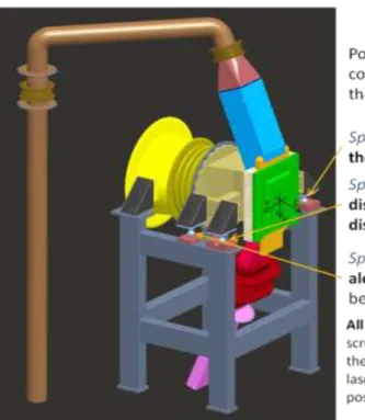
The newly developed TA integrated model (see Fig. 3) was presented at the DDD-II pre-design review meeting in Garching at the end of June 2012. This new model also comprises the following developments carried out in conjunction to the integration activity:
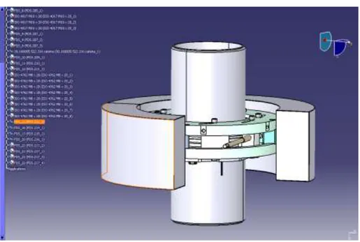
All the three mechanical connections (i.e., to the Li inlet and outlet pipes and to the accelerator beam duct), which were not included in the previous model, have been added. A solution based on the same concept previously known as Quick Disconnecting System (QDS) and now renamed (due to property rights issues following the change of the company to which the new contract for its development has been awarded) as Fast Disconnecting System (FDS) has been adopted for all of them. An additional FDS has also been introduced on the inlet pipe to allow for inlet bellow replacement (see Fig. 4)
A conceptual positioning and alignment system of the TA has been proposed (Fig. 5)
Support structures of the TA have been added (these are slightly different from those of JAEA design to accommodate the proposed installation system)
The whole compensating system including expansion bellows and dismantling joints to compensate thermal expansions and installation misalignment has been conceived (Fig. 6)
Fig. 3 – 3D view of the TA integrated system
Fig. 4 – TA mechanical connections based on FDS system TA chamber Skate System BackPlate Beam duct Fast Disconnecting system TA Support frame TA Installation System Reducer Nozzle Inlet pipe Flow Straightner Interface Frame Outlet channel
Fig. 5 – TA positioning and alignment system
The Fast Disconnecting System (FDS) permits to easily and rapidly connect and disconnect the flanges by simply acting (by remote) on a limited number of screws. The development of this component is still ongoing . A 3D view of the current preliminary FDS design for the inlet connection is shown in Fig. 7.
Fig. 7 - 3D view of the FDS
This system consists of a chain that provides, through a number of wedges, the force needed for compressing the sealing gasket between the flanges. Opening and closing of the chain mechanism is obtained by maneuvering two (or even one) driving screws. The design of the system also comprises the following features:
a supporting plate for system replacement
a Li leak detection system;
a safety unlocking system allowing the FDS opening in case of failure
a removable insulation system
The detailed description of the FDS along with the status of its design represents the object of another report of the present annual period of the current MSE-ENEA Agreement (RdS/2012/262).
Fig. 5 shows a sketch of the conceptual solution employed for the TA support structure. This system comprises three elements: the support frame, the installation equipment and the positioning device. The support frame serves two main functions:
support the TA and accommodate its installation equipment
keep the TA aligned with the beam during beam on conditions
In the current design, the frame is attached to the steel liner of the TTC floor, although its design is not finalized yet.
Since, due to nuclear heating, the frame is subjected to temperature increase, the right positioning of the TA and in particular its alignment with the beam can be lost during operation as a result of thermal expansions. Therefore, an active cooling of the frame is foreseen. The detailed requirements of such cooling system have not been defined yet.
Moreover, the attachments of the frame to the TTC floor liner must be designed in such a way that the whole structure formed by the frame and the supported TA is able to withstand the loadings produced by the reference earthquake. To this purpose, a seismic analysis must also be performed. Thermomechanical calculations considering nuclear heating and earthquake loading conditions on the support frame will be done in the future development stage.
Unlike JAEA design for the integral TA support structure, no guide rails are foreseen in this case, as it is assumed that every RH operation carried out on the BP or TA is made after that all the Test Modules placed behind the BP have been removed.
The installation equipment consists of a series of support points which together allow an isostatic arrangement of the TA leaving it free to thermally expand so to avoid stresses generated by hyper-constraints of the structure. The conceptual design of the installation system is shown in Fig 5.
Three types of support points are adopted:
o Sphere-on-cone (1 support point) which serves as a fixed point (all displacements on the x-z plane are prevented)
o Sphere-on-cylinder (1 support point) which prevent displacement along z, allowing free movements along x
o Sphere-on-plane (2 support points) which prevent movements along vertical (y) direction
The position of all support points can be regulated by means of adjusting screws so to exactly control the alignment of the TA with respect to the beam axis.
A laser tracking system is envisaged to check the exact position of the TA inside the TTC. As an example, a commercial system (LEICA absolute Tracker AT401) that could be used for this purpose is shown in Fig. 8. This device is capable to track objects from very long distances (up to 40 m) with a resolution of the order of tenth of mm in the worst case (see specification table in Fig. 8), which would permit to arrange it in the Access Cell (which is placed just above the TTC) when the TTC is open (as during TA replacement operations).
The installation system, the positioning device and the dismantling joints represent together an integrated system that allows to properly position the TA on the support structure and connect it to the beam duct and the Li loop.
The global procedure for the TA installation is foreseen as follows: 1) TA positioning and alignment with the beam
• Lowering of the TA on the support structure
• Check the TA position with respect to the beam axis by laser tracking system
• If not well aligned, regulate the TA position by means of the adjusting screws of the support points until TA position is within installation tolerances
2) Closure of the mechanical flanges
• Manoeuvre the driving screws on the dismantling joint of the beam duct to bring the FDS flanges in contact. Centring of the flanges are assured by a set of suitable pins provided on the FDS mating flanges.
• Close the FDS flanges by manoeuvring the dedicated bolt(s) • Proceed in the same way for the inlet and outlet flanges
• Inevitable installation misalignments of the FDS flanges are absorbed by the bellows of the dismantling joints.
Safety assessment of the Li Target Facility
As a further commitment within PA ED03-EU, ENEA has to perform the safety assessment of the whole Lithium Facility (LF) of IFMIF.
In the reference period, the main efforts were put on the preparation of the safety documents for the LF. Two important documents were elaborated: the LF Safety Requirements and the LF Safety Report. The LF Safety Requirements document is completed and had a first review by IFMIF PT in May 2012. The first revision has been finalized and sent for the approval at the end of June 2012. The LF Safety Report will be implemented in the Preliminary Safety Analysis Report (PSAR) provided in the frame of the EDA part of the IFMIF/EVEDA project. The first draft was reviewed by the IFMIF PT in May 2012. The first version of the document is now ready. Some important parts such as FMECA (Failure Mode, Effect and Criticality Analysis) will be finalized within September 2012, to include the last improvements of the design.
As to the LF FMECA, a suitable methodology based on the use of the risk matrix index has been proposed. A Preliminary Fire Hazard Analysis (PFHA) has been carried out. After revision and completion of the current LF PFHA and an accurate checking of the requirements for the interfaces with the other facilities, a final version of the IFMIF PFHA will be provided for DDD-II report and for the PSAR.
As a further contribution to the LF safety analysis, updated activation calculations have been also carried out to determine the radioactive inventory in the Li taking into account the Activated Corrosion Product (ACP) due to erosion/corrosion processes on the materials of the target components and lithium loop steel pipes. The activation calculation procedure for ACP assessment is reported hereafter (see Sec. Activation
Numerical analyses
Nuclear calculation
Neutronic calculations are performed by using the MCNP-5 Monte Carlo code [6] with the latest DeLicious neutron source code, the so-called “McDeLicious-11” [7], [8], provided by KIT.
This version includes the generation and transport of primary photons produced by the 6,7Li(d,xγ) reactions. Moreover, in this latest McDeLicious version, a new approach is implemented to enable the direct sampling from the tabulated deuteron beam distribution data without using fitting functions. In this approach, the beam entry position is sampled from tabulated data representing, actually, the intensity distribution of the impinging deuteron beam. The neutron cross sections of the FENDL-3 Starter Library, release 2 (FENDL-3/SLIB2), available on the IAEA website, is used in the calculations until the testing of the FENDL-3 Starter Library, release 4 (FENDL-3/SLIB4), will be completed.
Due to the complexity of the 3D TA model, an interface software tool able to import the CAD file into MCNP-5 code is needed. To this purpose the McCad conversion software developed by KIT has been recently procured by ENEA within the IFMIF cooperation activities. In the reference period, the installation of McCad on an ENEA local workstation has been completed and some training on its use has started. Preparation of a STEP file of the new integrated TA model suitable for its import into McCad software is currently on going.
Activation calculations for the Activated Corrosion Products (ACP)
In the IFMIF lithium loop an important risk of radiological exposure for the workers can arise from the presence of Activated Corrosion Products (ACP). The ACP, due to erosion/corrosion processes on the materials of the target components and lithium loop steel pipes, can continue to circulate in the lithium before being trapped/deposited and can be activated during the passage through the target due to both deuteron and neutron irradiation exposure.
Activation calculations have been performed in order to provide the radioactive inventories of Li containing ACP due to the irradiation of both neutron and deuteron fluxes. The activation calculations were performed using the EASY-2007 activation system (FISPACT code + EAF-2007 activation library).
For performing the activation calculations the following data/information are required:
a) Total amount of corrosion products and their isotopic composition in lithium (so called "Lithium mix composition")
b) Neutron spectrum in the lithium target c) Deuteron spectrum in the lithium target
d) Total time of irradiation exposure (irradiation scenario)
a) The "Lithium mix composition" considered in the present calculations is reported in Table 1. It contains lithium, lithium impurities and SS-316 steel corrosion products.
Table 1 – Elemental composition of the lithium used in activation calculations Element [wt- %] H 2.0E-03 Li 99.9832 C 1.0E-03 N 1.0E-03 O 1.0E-03 Al 5.0E-07 Si 1.0E-04 Ti 5.0E-07 V 4.2E-12 Cr 1.7E-03 Mn 5.0E-04 Fe 6.5038E-03 Co 9.0E-06 Ni 2.7E-03 Cu 2.0E-05 Nb 1.0E-06 Mo 2.4E-04 Ta 3.6E-05 W 1.8E-19 Ag 4.0E-06 Sn 1.0E-07 Sb 1.0E-07
An analysis of the solubility of metallic elements in lithium was performed by M.Ida and F. Groeschel [9]. On the basis of this study, a “soluble content” composition, in wt % at 300 oC , was provided, with the assumption, due to the lack of a dissolution model, that the dissolution of each element is equal to each solubility level depending on Li temperature. In the same document the composition used by R. A. Forrest in the activation calculations for IFMIF [10] was also considered. The elemental composition of Table 1 arises from a combination, based on a conservative approach, between the values from [9] and [10], choosing for each element the maximum one. This conservative assumption for the first assessment of worker doses was agreed in the IFMIF LF safety meeting held in Frascati on 10-11 May 2012. In the activation calculations it was assumed that during the irradiation time there is no filtering of the corrosion products.
b) Neutron spectrum in the lithium target
The neutron spectrum was calculated via the MCNP5 1.4 code [6] with the previous McDeLicious neutron source [11]. The full performance operation phase consisting of two beams of 125 mA of 40 MeV deuterons was considered in the transport calculation. An averaged spectrum in the lithium footprint target volume (20 ×5 × 2.5 cm3 ) was calculated in the VITAMIN-J + (211 energy groups structure) of the EAF-2007 group-wise neutron activation library (eaf_n_gxs_211_flt_20070). A total neutron flux of 1.25828×1015 cm-2 s-1 was obtained.
c) Deuteron spectrum in the lithium target
The deuteron spectrum was calculated via MCUNED code [11], that is an extension of the MCNPX 2.7d code, able to handle the deuteron evaluated cross section data libraries.
The full performance operation phase consisting of two beams of 125 mA of 40 MeV deuterons with FWHM=± 0.5 MeV was considered in the transport calculation. Due to the different behaviour of deuterons penetration in lithium with respect to neutrons, an averaged spectrum was calculated on a volume of 20 ×5 × 2.2 cm3. The spectrum was calculated in the VITAMIN-J + (211 energy groups structure) of the EAF-2007
group-wise deuteron activation library (eaf_d_gxs_211_flt_20070). A total deuteron flux of 1.1289×1016 cm
-2
s-1 was obtained. d) Irradiation scenario
The irradiation scenario has been determined on the basis of the following assumptions:
Lithium inventory=9m3
Lithium density=512 kg/m-3
Lithium mass=4608 kg
Lithium flow rate=130 l/s= 0.13 m3/s=66.56 kg/s
Footprint volume=2.5×10⁻⁴ m3
Irradiation time=2.5×10⁻⁴ m3 /0.13 m3s-1 =1.9ms On the average, 69 s are required to travel one loop.
This means that any material carried in the lithium will, on average, take 69 s to travel one loop and spend 1.9 ms exposed to neutron and deuteron fluxes during each circuit.
Thus in FISPACT calculation a series of pulses each of length 1.9×10⁻³ s followed by an off-time of 69s has to be modelled. Assuming an operation scenario of 345 days (20 days a year for maintenance) then the irradiation history has been represented as a constant irradiation for 345 days followed by 10 pulses. This type of modelling has been previously found to be physically realistic for FISPACT calculations [10]. The presence of the pulses prior to shutdown ensures that the production of short-lived radionuclides is modelled correctly.
During the 345 days of irradiation, the average flux used for neutrons was (1.9×10⁻³/69) ×1.25828×1015=3.464829×1010 cm-2s-1 while for deuteronswas (1.9×10⁻³/69) ×1.1289×1016=3.108565 ×1011 cm-2s-1, followed by ten 1.9 ms full-flux pulses.
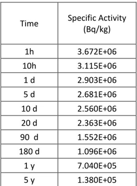
In Table 2, the specific activity for neutron activation without tritium contribute (i.e. only due to corrosion products) at the various cooling times is given.
Table 2 – Specific activity for neutron activation without tritium contribute.
Time Specific Activity (Bq/kg) 1h 3.672E+06 10h 3.115E+06 1 d 2.903E+06 5 d 2.681E+06 10 d 2.560E+06 20 d 2.363E+06 90 d 1.552E+06 180 d 1.096E+06 1 y 7.040E+05 5 y 1.380E+05
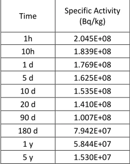
In Table 3, the specific activity for deuteron activation without
3H and
7Be (i.e. only due to
corrosion products) is given.
Table 3 – Specific activity for deuteron activation without 3H and 7Be contributes.
Time Specific Activity (Bq/kg) 1h 2.045E+08 10h 1.839E+08 1 d 1.769E+08 5 d 1.625E+08 10 d 1.535E+08 20 d 1.410E+08 90 d 1.007E+08 180 d 7.942E+07 1 y 5.844E+07 5 y 1.530E+07
The ratio of deuteron to neutron activity is shown in Fig. 9 (ratio between values of Table 2 and Table 3). The deuteron activation is 56 times more important than that due to neutrons at 1 hour cooling time rising up to 111 times at 5 years cooling time.
Fig. 9 – Ratio of deuteron to neutron specific activity (no
3H and
7Be )
The activation calculations provide also the decay gamma spectra which will be used for the dose
rates evaluation around the various devices of the lithium loop.
Energy deposition of D beams in the Li jet for thermo-hydraulics calculations
The deuteron power deposition profile in the lithium in the footprint area was calculated.
In the IFMIF design two linear accelerators are foreseen each generating 125 mA of 40 MeV deuterons. These beams stop in the lithium jet delivering a total power of 10 MW on a volume of 5×20 ×2.5 cm3. The deuterons lose their energy in lithium by both electronic and nuclear interactions. A validated computational approach able to simulate the deuteron transport and to evaluate the deuteron nuclear interactions and consequent production of secondary particles is required.
The calculations have been performed with the following procedure:
the MCUNED code was used [11], able to handle the deuteron evaluated cross section data libraries;
a curved profile of the lithium jet in the vertical direction and a complete geometry, including the Back Plate behind the lithium jet, were considered;
two deuteron beams of 125 mA impinging on the lithium surface at ± 9°;
the beam intensity profiles in the horizontal and vertical directions considered in the previous McDeLicious code.
a 2.5 cm thickness of lithium jet was considered with density 0.512 g/cm3;
the transport of deuterons, neutrons, protons and photons was considered;
the beam was treated with a Gaussian energy distribution around the average value of 40 MeV, with a FWHM= ± 0.5 MeV (total FWHM=1 MeV).
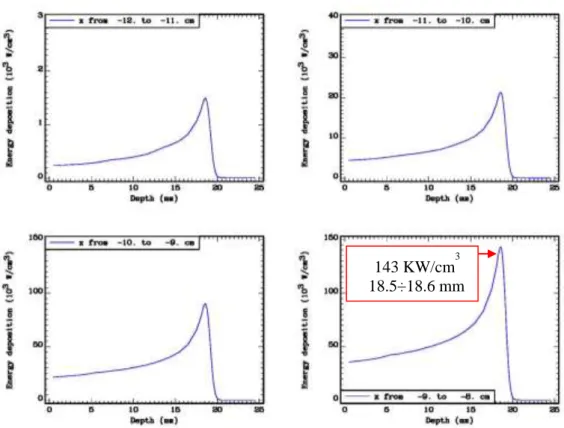
In order to take into account the variation of the beam intensity along the horizontal direction, the calculations were performed by considering a 24 cm width of the lithium jet and subdividing it in 24 bins of 1 cm each. For each bin the total energy deposition profile (W/cm3) vs. lithium depth (mm) was calculated. In the vertical direction only one bin was considered in the calculations, due to the nearly flat behaviour on the footprint.
In Figs. 10, 11, 12 the power deposition profiles are reported for the range between -12 ÷0 cm (due to the geometrical symmetry of the system, the corresponding profiles in the range 0÷12 cm are the same). The height and the position of the Bragg peaks are also indicated.
Fig. 10 – Power deposition vs. Li depth (-12 < x < -8 cm)
Fig. 11 - Power deposition vs. Li depth (-8 < x < -4 cm)
103 KW/cm3 18.5÷18.6 mm
143 KW/cm3 18.5÷18.6 mm
Fig. 12 - Power deposition vs. Li depth (-4 < x < 0 cm)
New calculations of the deuteron beam energy deposition will be performed using the beam intensity profile of the last “McDeLicious-11”[7,8].
Cost evaluation (rough)
The main items to be considered for a preliminary cost evaluation of the IFMIF TA system including their related RH tools are the followings:
TA material (EUROFER, about 1 ton)
TA manufacturing
FDS
RH tools
Other equipment (expansion joints, insulation, heaters, instrumentation, ...)
The EUROFER material is quite expensive due to its limited production (until now, it is produced mainly for research purposes). Presently, its costs is about 120 €/ kg, therefore an amount of 120-150 k€ plus adequate margins (for cutting, manufacturing,...) is to be considered for the TA crude material.
TA manufacturing is estimated of the same order of cost (~100-150 k€) considering the delicate and in some cases difficult machining operation needed. A realistic estimate cost for the entire TA including manufacturing should be approximately 350 - 400 k€.
Ordinary Fast Disconnecting Systems can be easily found on the market. However, their application in IFMIF needs a significant customization of these components and therefore their costs are higher than the commercial ones. A cost of about some tens of thousands Euros can be envisaged in total for the all three connections.
106 KW/cm3
In any case, The major cost source is certainly represented by the RH tools since, due to the high radiation environment expected in the TTC, they must be fabricated using electronics in RadHard (Radiation-resistant) version whose cost is tremendously higher than that of usual electronic components (even up to 10 times more).
The cost of other equipment (expansion joints, insulation, heaters, instrumentation, ...) is the ordinary one for this kind of components.
Conclusions
During the present annual period covered by the MSE-ENEA Agreement, most of the work has been done to advance the design of the IFMIF Target Assembly with bayonet Backplate in the framework of the current European Engineering Design Activities of IFMIF/EVEDA project. The work has been mainly focused on the improvement of the system design by introducing several missing features (support structures, positioning system, compensating system,...) and on its integration into the Li loop and the Test Cell models.
This newly developed integrated design will be used in the next phase as a working model to be imported into the numerical codes used to perform the supporting calculations (neutronics, thermomechanics, thermohydraulics, safety and RAMI analysis). Some of these calculations have already started and their main outcomes are briefly summarized in this document.
References
[1] P. Garin, M. Sugimoto, “Main baseline of IFMIF/EVEDA project”, Fus. Eng. Des., 84 (2009) 259-264. [2] H. Nakamura et al., “Status of engineering design of liquid lithium target in IFMIF-EVEDA”, Fus. Eng.
Des., 84 (2009), 252–258.
[3] D. Bernardi, Procurement Arrangement PA ED03-EU, IFMIF DMS ref. BA_D_2233KM
[4] D. Bernardi et al., “Rapporto di avanzamento del progetto del target di IFMIF comprensivo di disegni e di analisi numeriche”, MSE-ENEA Agreement Report RdS/2011/387 (2011)
[5] D. Bernardi, “DDD-I of IFMIF Lithium Target System (EU)”, IFMIF DMS ref. BA_D_22EY48 [6] MCNP5-1.40 RSICC Release Notes", LA-UR-05-8617 (2005)
[7] K. Kondo, F. Arbeiter, U. Fischer, D. Große, V. Heinzel, A. Klix, A. Serikov, K. Tian, V. Weber, New Beam profile and neutronic response — DPA distribution in HFTM, IFMIF wokshop, Naka December 2011. [8] S. P. Simakov et al, “Status of the McDeLicious Approach for the D-Li Neutron Source Term Modeling in
IFMIF Neutronics Calculations”, to be published in Fusion Science and Technology, 62, 2012.
[9] M. Ida and F. Groeschel, Estimation on Elements in the Lithium of IFMIF Lithium Loops, private communication
[10] R.A. Forrest, M.J. Loughlin, Neutron and deuteron activation calculations for IFMIF, Journal of Nuclear materials 367-370 (2007) 1568-1573.
[11] P. Sauvan, J. Sanz, F. Ogando, “New capabilities for Monte Carlo simulation of deuteron transport and secondary products generation”, Nucl. Instr. And Methods in Physics Research A 614 (2010) 323-330.
Acronyms
ACP Activated Corrosion Products
AF Accelerator Facility
BP Backplate
CF Conventional Facility
DDD Design Description Document
dpa displacement per atom
EDA Engineering Design Activities
D Deuteron
EVEDA Engineering Validation and Engineering Design Activities
FDS Fast Disconnecting System
FMECA Failure Mode, Effect and Criticality Analysis IFMIF International Fusion Materials Irradiation Facility
JAEA Japan Atomic Energy Agency
LF Lithium Facility
PA Procurement Arrangement
PFHA Preliminary Fire Hazard Analysis
PIE Post Irradiation Examination
PT Project Team
RAMI Reliability, Availability, Maintainability, Inspectability
RH Remote Handling
TA Target Assembly
TTC Target and Test Cell
TF Test Facility

![Table 1 – Elemental composition of the lithium used in activation calculations Element [wt- %] H 2.0E-03 Li 99.9832 C 1.0E-03 N 1.0E-03 O 1.0E-03 Al 5.0E-07 Si 1.0E-04 Ti 5.0E-07 V 4.2E-12 Cr 1.7E-03 Mn 5.0E-04 Fe 6.5038E-03 Co](https://thumb-eu.123doks.com/thumbv2/123dokorg/5616492.68375/14.892.295.597.193.591/table-elemental-composition-lithium-used-activation-calculations-element.webp)