85 CHAPTER 4-GLASS:MATERIALS &PRODUCTS
C
HAPTER
4
G
LASS
:
M
ATERIALS
&
P
RODUCTS
“Shadows were the brush work of the ancient Architect. Let the modern now work with light, light diffuse, light reflected, light for its own sake, shadows gratuitous.”
Frank Lloyd Wright
4.1 G
LASS
:
C
OMPOSITION
,
P
HYSICAL AND
M
ECHANICAL
P
ROPERTIES
Glass is a hard, optically transparent, brittle material with a high-softening point and it is relatively insoluble in most substances. It has been defined as an inorganic product of fusion that has cooled to a rigid condition without crystallizing [84].
This definition implies that glass is amorphous (non-crystalline) isotropic material, so that its physical condition is related to the liquid state, hence the term super cooled liquid may be used to describe glass (Fig. 1).
Fig. 1 . Soda-lime-silica glass presents an amorphous grid, where Sodium (Na) is used
to reduce the melting temperature. Fig. 2 Effect of temperature on the viscosity of glass.
The viscosity has an exponential dependence on inverse temperature and thus decreases rapidly as temperature rises (Fig. 2). The viscosity is significantly affected by trace
86 CHAPTER 4-GLASS:MATERIALS &PRODUCTS
impurities. Soda-lime glass (Fig. 3), the most diffuse type of glass in building construction, representing 80% of all commercial glass, is a combination of silica dioxide, combined with lime and other several minor additives, while the fusion process is favoured by an alkaline substance, sodium carbonate, magnesium, alumina and other components.
Another type of glass, which main constituents are silica and boron oxide, is borosilicate glass (Fig. 4). Borosilicate glass presents very low coefficient of thermal expansion (3.3 x 10⁻⁶/K), making them resistant against thermal shock. It is used in laboratory application due its chemical and thermal resistance, but it is rather exceptional in construction because it is more expensive than soda-line glass. The chemical composition of soda-lime glass and of borosilicate glass, with the role played by each component, is listed below:
COMPONENT PERCENTAGE IN WEIGHT MAIN FUNCTION
SODA LIME SILICA GLASS
BOROSILICATE GLASS
Silica sand SiO2 69-74% 70-87% Basic constituent.
Soda Na2O 12-13% 0-8% Lowers the melting point.
Lime CaO 5-10% - Stabilizing anti-solvent.
Magnesia MgO 0-6% - Increases the chemical stability. Alumina Al2O3 0-3% 0-8% Increases the chemical stability.
Boron-Oxide B2O3 - 7-15% Improves the thermal shock resistance.
Others K2O 0-6% 0-8% Chemical grid modifier.
Fig. 3 Soda-lime glass panes. Fig. 4 Borosilicate tubes.
The most significant physical-chemical properties of glass are hardness (5-7 degrees on the Mohs scale), transparency and fragility. Some important physical properties of glass are shown in the table below:
87 CHAPTER 4-GLASS:MATERIALS &PRODUCTS
GENERAL CHARACTERISTICS SODA LIME SILICA GLASS BOROSILICATE GLASS
DENSITY kg/m3 2500-2750 2200-2500
YOUNG’S MODULUS GPa 63-77 70-74
POISSON’S RATIO - 0.22-0.24 0.2
HARDNESS MoH 5-7 4.5-6
THERMAL CONDUCTIVITY W/mK 1 1
COEFFICIENT OF THERMAL EXPANSION 10-6K-1 9 Class 1: 3.1-4.0
Class 2: 4.1-5.0 Class 3: 5.1-6.0 Glass has mechanical properties similar to those of crystalline solids; it presents elastic properties and strength, but it has no plasticity and thus has no yield point (Fig. 5 a, b, c, d). Due to the absence of slip planes or dislocations glass presents almost perfectly elastic isotropic behaviour and brittle fracture [24].
MECHANICAL BEHAVIOUR -CHARACTERISTICS
TENSILE STRENGTH N/mm2 20-200*
COMPRESSIVE STRENGTH N/mm2 221-1000
FRACTURE TOUGHNESS MPa m1/2 0.78
Fig. 5 a, b, c, d. Tensile behaviour for different building materials.
MAIN CHARACTERISTICS OF GLASS
Linear elastic behaviour: absence of yield strength. Absence of plastic and viscous phenomena. Sensitivity to stress concentration (absence of
plastic adaptation).
Sensitivity to the presence of defects (low toughness).
Sensitivity to the size of the sample. Sensitivity to the duration of the loads.
(*) The “tensile strength” is generally the most significant property in glass design, and it is influenced by environmental condition and also depends on amplifiers (micro-defects) generally present on the surface within the forming process and the subsequent manipulations.
88 CHAPTER 4-GLASS:MATERIALS &PRODUCTS
The theoretical tensile strength of glass depends on the covalent bond rupture and should be around 32,000 N/mm2; however annealed glass fails at levels well below 100 N/mm2. The reason for this discrepancy is the presence of stress raising flaws on the surface of the glass, knows as Griffith flaws (Fig. 6), which come from manufacturing process, handling, weathering etc. etc.. The increasing depth of this flaws causes a reduction of the tensile strength of the glass. Flaws do not propagate in presence of compression: the compressive strength of glass is therefore much larger than the tensile strength. All these models consider that the tensile breaking is associated with the propagation of an existing crack, which propagation is influenced by the duration of load application. In glass elements, the tensile strength is determined by the flaw that has a greater stress intensity factor, regardless of the presence of other flaws on the surface.
Glass elements are also affected by a specific phenomenon, called static fatigue. It means that the tensile strength of the material decreases when subjected to constant and long-term loads. However, strength and mechanical properties of glass are very variable and depend on several factors, such as:
SURFACE CONDITION.
Fig. 6 Griffith Flaw.
STRESS HISTORY: INTENSITY/DURATION OF LOADS.
SIZE OF STRESSED AREA.
RESIDUAL STRESSES.
ENVIRONMENTAL CONDITION.
Therefore, glass tensile strength shall be assessed using a model based on fracture mechanics principles; such models are available in scientific literature (Load Duration Theory, Brown, 1972; Crack Growth Model, Evans, 1974; Glass Failure Prediction Model, Beason, 1980). All these consider that the traction breaking is associated with the propagation of an existing crack, that is influenced the time of load application [7]. Nowadays, the most advanced prediction model of strength in glass elements consists of a
89 CHAPTER 4-GLASS:MATERIALS &PRODUCTS
lifetime prediction model for structural glass elements, based on fracture mechanics and the theory of probability [7]. The Lifetime Prediction Mode (LPM) has been formulated by M. Haldimann in 2006.
In his approach, Haldimann finally finds the general expression of the failure probability, to describe the glass mechanical behaviour during life time of whatever glass elements. It contains no simplifying hypotheses that would restrict its applicability to special cases and it offers great flexibility with regard to the representation of the surface condition [38].
Due to the analytical complexity of the LPM, the application of the method in the current design practice may be too difficult. The same Haldimann suggested a simplified version of its formulation, introducing the hypothesis that, however, are in favour of safety.
On the basis of Haldimann’s approach, a new design method has been developed by M. Froli and M. Santarsiero [38]. The Design Crack Method (DCM) proposes an analytical simplicity which aims to achieve, through a semi-probabilistic approach, a tool that supports all those professionals who are preparing to design glass elements, using a computational model that preserves the general validity of rigorous methods.
The LPM do not allow to take account of aleatory behaviour of several factors that affect the problem of the resistance of the glass. To overcome this problem, a “design crack” has been defined, such as to represent in a probabilistic manner the state of damage of the random real surface of a glass element. The aim of the proposed method is not so much to obtain a rigorous solution of the complex problem of glass strength, but rather to have the order of magnitude of the phenomenon, taking account of the main factors that govern the mechanical strength of a glass element in time, such as static fatigue and stress concentration at the apex of the cracks.
The semi-probabilistic approach is in line with the design philosophy of the Eurocodes, as the probability of failure is assumed as a parameter depending on the degree of security that you want to obtain [38].
Furthermore, the verification method does not require the use of specially developed software and maintains a general validity of application to vary the geometry of the element, the environmental conditions, constraints, stresses.
90 CHAPTER 4-GLASS:MATERIALS &PRODUCTS
4.2 P
ERFORMANCE
D
ATA OF
G
LASS
Window and façade systems are comprised of glass panes, structural frames, spacers, and sealants. In recent years, the variety of glass types, coatings, and frames available for use in window systems has increased widely, as the opportunity to optimize glazing selection on a project-by-project basis.
Many differing data are used to assess the performance of glasses. None should be considered in isolation and all should be reviewed giving importance to geographical location and glass orientation on the building.
4.2.1
T
HERMALI
NSULATIONHeat loss is quantified by the thermal transmittance or U value (U). The U value, usually expressed in S.I. units (Système Internationale d’Unités) of W/m²K, is the heat flux density
through a given structure divided by the difference in environmental temperatures on either side of the structure in steady state conditions. It is more generally referred to as the rate of
loss of heat per square meter, under steady state conditions, for a temperature difference of one Kelvin (or one degree Celsius) between the inner and outer environments separated by the glass, or other building element. As the U-value increases, so does the amount of heat that is transmitted through the glazing material; the lower U-value, the greater a product’s resistance to heat flow and therefore the better performance of the product [8].
The U-value is a benchmark for the comparative efficiency of thermal insulation for the building elements. For insulated glass units U-values are based on centre-of-glass calculations. The bigger the air space in an IG unit, the better the U-values, up to 20mm, thereafter convection within the air space reduce its effectiveness.
The different variables that influence the calculation of the thermal transmittance of windows, doors and shutters are:
the type of glass; the type of frame;
91 CHAPTER 4-GLASS:MATERIALS &PRODUCTS
The thermal transmittance of whole transparent element is called Uw and can be calculated in accordance with DIN Standard, that has been adopted by EN ISO 100771 and -2. The calculation of U-value is based on three component parts: the thermal transmittance of the glazing; the thermal transmittance of the frame; the linear thermal transmittance of the frame/glazing junction. The Uw [W/m2K] value for the whole element can be therefore calculated as follows:
Where:
Ug is the thermal transmittance of the glazing or of the central glazing pane for an IGU [W/m2K];
Ag is the visible glazing area [m2];
Uf is the thermal transmittance of the frame [W/m2K]; Af is the frame area [m2];
Ѱg is the linear thermal transmittance of the junction, due to the combined thermal effect of glazing, spacer and frame in case of an IGU [W/mK];
lg is the perimeter of the glazing;
Aw is the area of the window/door/facade etc., (Ag+Af).
R-value is the measure of a material’s resistance to heat flow and it is expressed as the inverse or reciprocal of U-value (R=1/U).
K-value, or thermal conductivity λ, is the measured value of heat flow that is transferred through an area of 1 m2 at a temperature difference of 1K. The units of measures in SI are therefore W/mK. Thermal conductivity of materials is temperature dependent. The reciprocal of thermal conductivity is thermal resistivity.
92 CHAPTER 4-GLASS:MATERIALS &PRODUCTS
4.2.2
V
ISIBLEL
IGHT ANDS
OLARE
NERGYThe visible light characteristics and solar properties of glass are extremely important to proper glass selection on any project. Selection of a glass with the most favourable combination of light and solar transmittance, reflectance and absorption is imperative to meet the end use criteria. In selecting the right visible and solar energy properties for a given project, it is vital to evaluate day-lighting requirements, building type, size and orientation, local climate, the importance of outside viewing, interior/exterior shading devices, glare, heat/cooling demands and aesthetics.
The solar radiation that reaches the earth consists of 3% ultra-violet rays (UV), 55% infra-red radiation (IR) and 42% visible light. These three components of solar radiation each correspond to a range of wavelengths. Ultra-violet extends from 0.28 to 0.38 μm (nanometres), visible light from 0.38 to 0.78 μm and infra-red from 0.78 to 2.5 μm.
The overall energy distribution of solar radiation, as a function of the wavelength between 0.3 and 2.5 μm (spectrum), for a surface perpendicular to this radiation, is represented by the curve shown below (Fig. 7). This spectrum draws on definitions provided in EN 410 and certain atmospheric constants concerning the characterisation of the air and the diffused radiation [8].
Fig. 7 Solar Radiation Spectrum. Fig. 8 Glass energy properties.
Glass manages solar radiation from the sun by three mechanisms: transmittance, reflectance and absorptance (Fig. 8), which for solar control purposes are defined in terms of the following parameters:
93 CHAPTER 4-GLASS:MATERIALS &PRODUCTS
DIRECT SOLAR ENERGY TRANSMITTANCE (ET) is the proportion of solar radiation at near normal incidence that is transmitted directly through the glass.
SOLAR ENERGY REFLECTANCE (ER) is the proportion of solar radiation at near normal incidence that is reflected by the glass back into the atmosphere.
SOLAR ENERGY ABSORPTANCE (EA) is the proportion of solar radiation at near normal incidence that is
absorbed by the glass.
Total Solar Energy Transmittance (TET) or Solar Heat Gain Coefficient (SHGC), also known as g value or solar factor (defined in EN 410), is the fraction of solar radiation at near normal incidence that is transferred through the glazing by all means. It is composed of the direct transmittance, also known as the short wave component, and the part of the absorptance dissipated inwards by longwave radiation and convection, known as the longwave component. The proportions of the absorbed energy that are dissipated either inside or outside depend on the glazing configuration and the external exposure conditions.
4.2.3
V
ISIBLEL
IGHTVisible light, or daylight, is the range of wavelengths of the electromagnetic spectrum between 0.38 μm and 0.78 μm. The combined wavelengths of the visible spectrum when acting on the eye, result in the physiological effect known as vision. The light transmittance and light reflectance factors are the ratios of the transmitted or reflected light flux to the incident light flux, as explained in the table below.
LIGHT TRANSMITTANCE (LT) is the proportion of visible light at near normal incidence that is transmitted through the glass.
LIGHT REFLECTANCE (LR) is the proportion of visible light at near normal incidence that is reflected by the glass.
COLOUR RENDERING INDEX (RA) expresses the colour rendering properties of glass in transmission (on a scale of 0 to 100, with a value of 100 representing optimum colour as seen in direct visible sunlight).
Solar radiant energy entering a room through the glass is absorbed by interior objects and surfaces, which then retransmit the energy as thermal radiation, mainly in the far infra-red band (above 5 μm). Even ordinary float glass is practically opaque to radiation with a
94 CHAPTER 4-GLASS:MATERIALS &PRODUCTS
wavelength higher than 5 μm. This means that solar energy entering through the glass is trapped in the room, which then tends to heat up and is referred to as the “greenhouse effect”.
The Selectivity index S of a glass is the light to heat ratio and can be expresses: (S = LT / TET) or (S = LT / SHGC).
Knowing the light transmittance factor of a particular glass makes it possible to assess the level of available light inside a room, when the exterior light level is also known. The ratio of the internal light level at a given point in a room to the exterior light level measured on a horizontal plane is constant, regardless of the time of day. The ratio of internal light levels to external light levels is referred to as the daylight factor and is usually expressed as a percentage [86].
4.3 E
VOLUTION OF GLASS MANUFACTURING TECHNIQUES
The origins of glass as a material are ancient. In the 5th millennium BC some Phoenician merchants managed to cause melting of the sand together with Natron (sodium carbonate decahydrate), forming a transparent liquid. Glass making technologies increased in Egypt during the Late Bronze Age; discoveries of the period included coloured glass vessels: early Syrian and Egyptian glass was a simple melted mixture of soda ash, lime and sand that was sculpted into final shapes while it was still hot. Glass was a luxury item and early glass work consisted of techniques learned from other trades, such as stone working, therefore the cooled glass was often ground and carved [46].
During the first century BC, the Romans put up the production for blowing into moulds; this discovery probably occurred when glassmakers switched to hollow metal rods to hold the sand cores and found that molten glass could be blown into shapes. Glass blowing paved the way for the increase in glass production that occurred throughout Roman times: glass vessels became easy and quite affordable to produce, even if glass as a building material for windows was used only for noble houses and important buildings. The window glass, which
95 CHAPTER 4-GLASS:MATERIALS &PRODUCTS
originated at the end of the third century, was thick and translucent, then it let light pass in but did not allow people to see out.
With the breakdown of Roman world, glassmaking technology stagnated in Europe; from 500 to 600 A.D. some techniques were developed and succeeded in producing flat glass for blow moulding of a sphere and its subsequent enlargement for rotation in the oven. It was followed by the moulded glass "roller", which was for centuries the only flat glass used in construction. During the 13th Century, on the Italian island of Murano was made a technical breakthrough, with the manufacture of flat glass for blowing cylinders, then cut and annealed, were then laid. Murano glass, that was quite clear and transparent, became popular throughout Europe. In the Middle Ages, glass was made by hand, mainly by blowing the molten glass into a flat disc which was spun so that it would thin out and flatten (Fig. 9 and 10).
Fig. 9 Crown glass. Fig. 10 Broad sheet and cylinder glass.
In the 16th and 17th Centuries, due to a shortage of trees, the English discovered that burning coal instead of wood in furnaces produced a clearer glass. Although the panes were wavy, full of bubbles, people could see through this kind of windows. The first transparent flat plates were obtained by Frenchman Louis Lucas de Nehou, who developed a cumbersome process for making plate glass. The process was long and extremely expensive. Over the next two hundred years, the process was improved, but the French plate glass method remained the basic technique [84].
In the 19th Century various procedures were industrially improved, due to the development of improved processes and the use of electricity. Compressed air technology led to the production of large lites of glass; controlled amounts of air were used to blow a
96 CHAPTER 4-GLASS:MATERIALS &PRODUCTS
large glass cylinder, which was reheated and allowed to flatten; then glass could be grinded and polished.
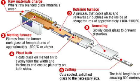
In the 20th Century machines were developed to improve glass manufacturing, but the main discovery was the float glass process, developed by Sir Alastair Pilkington and Kenneth Bickerstaff of the UK Pilkington Brothers between 1953 and 1957. The process consists of melting the raw materials at 1500-1600° C in a furnace and a continuous ribbon of molten glass flows into an enclosed pool of tin and floats due to its lower density; the continuous ribbon of glass slowly cools as it travels through an annealing oven to minimize residual internal stresses. As the glass cools rapidly from 1100°C to 800°C in the float bath, its viscosity increases and prevents crystallisation, becoming an amorphous isotropic solid (Fig. 11). From the 60s the float procedure was able to achieve high levels of quality.
Fig. 11 Modern float glass process, AGC Courtesy.
Nowadays, the glass manufacturing industry is much more sophisticated and produces a wide range of glasses, depending on the functions that the glass must perform. The production of one single float line (Fig. 12) consists of:
900 M FLOAT GLASS (4MM) PER HOUR
Fig. 12 A float line.
700 TONS PER DAY
70,000 M3 FLOAT GLASS PER DAY
97 CHAPTER 4-GLASS:MATERIALS &PRODUCTS
4.4 G
LASS PRODUCTS
:
O
VERVIEW
Glass is a material that both separates and visually joins space by means of its transparency. Nowadays the designer has a multitude of glass products from which to choose to achieve the desired finished look and to meet the requested performance of his building. Considering the comfort and energy savings, innovation in glass industry is moving towards two main roads.
On one hand, there have been technological advances in glass primary and secondary manufacturing to substantial improvements of the safety requirement and the thermal properties of glazing (transmittance, U-value; solar heat gain coefficient, G-value). Several systems are produced, with a thermal performance ever higher or close to the opaque envelopes the improvements are such that the frame is often the major source of thermal bridging in a contemporary glazed façade. Much of the architectural glass produced is now coated with different kind of coatings to enable the production of more energy efficient windows/façades. As with any advanced technology, there are several different production methods and the products have different properties. These materials, that are shown in the following sections, are widespread and easily available, since they are cost effective and provide controlled and reliable performance [8].
On the other hand, industry has recently produced types of glass able to adapt to the changing needs of user comfort, the variation of the climatic characteristics and aesthetic requirements, known also as smart glasses. Several innovative products have been developed (self-cleaning glasses, chromogenic products etc. etc.), in order to improve the climate and lighting control, cleaning and energy production: their characteristics are illustrated in the section below. The final aesthetics of smart products include such factors as glass substrate colour, coating colour and type, coating position and glass texture. The long-term behaviour of such products is not always clearly assessed and sometimes their cost is quite high, but high performance glasses are becoming even and even available and it appears that the technologies currently under development will improve the performance of static glass even further [18].
98 CHAPTER 4-GLASS:MATERIALS &PRODUCTS
4.4.1
G
LASS“T
RADITIONAL”
P
RODUCTS4.4.1.1PRIMARY MANUFACTURE:ANNEALED GLASS
Annealed glass is often used in architectural applications to resist loads and minor thermal stresses where a safety glazing product is not required to meet standards or buildings codes. More than 90% of all flat transparent glass worldwide is produced using the float glass process, also known as the Pilkington process.
Annealed glass is heated above a transition point and then it is allowed to cool slowly, without developing internal stresses caused by heat treatment. At the annealing point (η = 1013 Poise) stresses relax within several minutes, while at the strain point (η = 1014.5 Poise) stresses relax within several hours. As the glass cools, the outside will always cool faster than the inside. As glass cools it contracts. If the outside of the glass cools much faster than the inside, the outside glass contracts faster than the inside glass [1].
This variance in contraction causes stress in glass. Too much stress and the glass breaks. The slower the glass is cooled, the less the amount of temperature variance throughout the glass and less the amount of stress that will develop.
The cooling of glass is most important between the annealing temperature and the strain point. As explained, glass will develop stress in itself through the cooling process. The strain point is a point in temperature at which any stress that develops below that temperature in the glass through the cooling process is only temporary.
Stress that develops in the glass above the strain point is permanent. Once the glass has stabilized to room temperature, temporary stresses will disappear.
Float glass is annealed during the manufacture process and after that, the material can be cut to size, drilled or polished, with no significant residual stresses. The edge finishing can vary, depending on the specific application-. For glass in buildings the most typical edge diagrams are as follows:
99 CHAPTER 4-GLASS:MATERIALS &PRODUCTS
EDGE DIAGRAM DESCRIPTION TYPICAL APPLICATION
Flat ground Silicone structural glazing with exposed edges.
Flat polish Silicone structural glazing where edge condition is critical for aesthetic purposes.
Ground Miter Silicone structural glazing.
Seamed edges Edge treatment for heat-treated glass.
Annealed glass still carries the risk of sudden failure caused by nickel sulfide (NiS) inclusions and breaks into large shards that can be dangerous in several architectural applications [84].
There are other different types of annealed glass: sheet glass, plate glass, patterned glass, wired glass. The quality requirements for all of them are mainly listed in EN ISO 572-1, 572-2, 572-8 and are mandatory for the European glass market.
TYPICAL STOCK SIZE 6 x 3.21 m.
Possible oversized sheets
THICKNESSES 2-3-4-6-8-10-12-15-19-25 mm. 4mm thick glass is not normally favoured because it does not have sufficient strength as a monolithic lite for most curtain wall requirements and the wastage factor during processing tends to be excessive, especially in laminating.
THICKNESS TOLERANCE + 0.2mm for glass up to 6 mm thick.
+ 0.3mm for glass between 8 mm and 12 mm thick. + 0.5mm for glass 15 mm thick.
100 CHAPTER 4-GLASS:MATERIALS &PRODUCTS
4.4.1.2SECONDARY MANUFACTURE:TOUGHENED GLASS
Toughened glass, or tempered glass, is an type of glass that has been treated by thermal or chemical treatments to make it stronger and more resistant to heat, if compared with annealed glass. Tempering causes internal stresses which increase the tensile strength: thereby, glass will break in smaller particles, preventing injury [8].
Tempered glass is used when strong, safe and thermal resistant glass is called for. Toughened glass is made from annealed glass via two main manufacturing process: heat or chemical strengthening.
A) HEAT STRENGTHENING
The strength (modulus of rupture) of annealed glass can be increased by subjecting the glass to a secondary heat-treating process, known as tempering (Fig. 13), which consists of heating the glass to near its softening point (650°C) and then quickly cooling it with air (quenching). The relative speed of cooling results in the surface solidifying in a state of compression and the centre in tension (Fig. 14). Depending on the level of surface or edge compression, the finished product is classified as either fully tempered or
heat-strengthened.
Fig. 13 Tempering process. Fig. 14 Distribution of internal stress.
B) CHEMICAL STRENGTHENING
The chemical strengthening process toughens soda lime and other glass substrates through a sodium and potassium ion-exchange process in a salt bath, at a temperature higher than 380°C (Fig. 15): this produces the effect of the gradients of the respective electrochemical potentials, and therefore an exchange between the sodium ions present in the glass surface, and the potassium ions contained in the salt (Fig. 16). The introduction of potassium ions with dimensions substantially greater than those of the ions of sodium, involves as a consequence, the establishment of a system of residual stresses characterized by compressive
101 CHAPTER 4-GLASS:MATERIALS &PRODUCTS
stresses on the surface offset by the tensile stresses inside the glass.
The process imparts a higher strength, durability, and MOR (Modulous of Rupture, which is resistance to breaking in bending) as well as maintaining higher surface quality (80/50 and up to 60/40 for smaller applications). Chemical strengthening is best suited for thin display applications (3mm and under, though can be up to 6mm) as well as applications where optical distortion must be kept to a minimum. Glass can be strengthened from 8 to 16 hours imparting an MOR of 165 Mpa (24 Kpsi) and case depth of 16-19 um for the 8 hour cycle and an MOR of 220 Mpa (32 Kpsi) and case depth of 22-27 um for the 16 hour cycle.
Fig. 15 Chemical-strengthening furnace
Fig. 16 Ion Exchange Mechanism
Chemical strengthening and heat strengthening/tempering are both processes for increasing the strength and durability of soda lime and other glass substrates. Chemical tempering process becomes necessary in the following situations:
When the thickness of the glass to be quenched, it is less than 2.5 mm. Below this thickness, the application of the process of thermal tempering becomes almost impractical;
In case of glasses with very complex curvature or dimensional characteristics that could not be in any way considered by the installations of thermal tempering.
When mechanical strength higher than those normally obtained by thermal tempering are required.
Need for impact resistance higher than those obtainable with the traditional thermal quenching.
Need to get in addition to the mechanical strength, high optical requirements or total absence of surface deformation on the glass, for industrial applications or vehicle.
The stress profile of the two types of glass is different, as shown in the figure below (Fig. 17). There are attempts by the research and industry, to combine the advantages of both
102 CHAPTER 4-GLASS:MATERIALS &PRODUCTS
treatment, subjecting the glass before the thermal tempering and then to the chemical or vice versa (M. Overend, M. Zaccaria, 2013), in order to optimize performance and stress profile. Currently, the chemical tempering is a more expensive and less widespread.
HEAT-STRENGTHENED GLASS CHEMICAL-STRENGTHENED GLASS
Fig. 17 Stress profiles comparison
Heat strengthening and full tempering require a 3mm or thicker glass substrate and generally can only maintain 120/80 surface quality while imparting a higher thermal strength and a safety dicing break pattern (when broken dices into many small pieces for safety) for fully tempered parts. The heat strengthening process is utilized when a full temper is not possible due to thickness, size, or low thermal expansion rate of the substrate.
Fully tempered (toughened) glass is approximately four times as strong as annealed glass of the same thickness and configuration. It must comply with the requirements of EN 12150: Parts 1 & 2. When broken, it shatters into myriads of small fragments of more-or-less cubical shape which tend to vacate the opening as either individual small pieces or in interlocking clumps. The typical process to produce thermally tempered glass involves heating the glass to over 600 degrees Celsius, then rapidly cooling to lock the glass surfaces in a state of compression and the core in a state of tension as shown in the figure (Fig. 18).
Due to this relatively safe break pattern, fully tempered glass is often referred to as "safety glass" because it meets the requirements of the various European Building Regulations and Standards that set standards for safety glass. This type of glass is intended for general glazing, and safety glazing such as in sliding doors, building entrances, bath and
103 CHAPTER 4-GLASS:MATERIALS &PRODUCTS
shower enclosures, interior partitions and other uses requiring increased strength and safety properties. Tempered glass cannot be further processed, such as cutting, drilling, edge grinding, after toughening and any alterations, such as sandblasting or acid-etching will weaken the glass and can cause premature failure [84].
Fig. 18 State of Tension
Heat-strengthened glass is approximately twice as strong as annealed glass. Its breakage characteristics can vary considerably due to the acceptable range of surface compression. . Heat strengthened glass must comply with all the requirements of EN 1863: Parts 1 & 2. Heat strengthened glass has greater resistance to thermal loads than annealed glass and, when broken in service, the fragments are typically larger than those of tempered glass. Heat strengthened glass is not a safety glass product as defined by European Building Regulations and Standards. This type of glass is intended for general glazing, where additional strength is required to withstand wind load and thermal stress. However, when in laminated form, heat-strengthened glass is accepted as a safety glass, adding thermal breakage safety and enhanced strength to the other benefits of glass retention, sound absorption and security. Because of current technical limitations in the heat-treating process, heat-strengthening is restricted to glass not thicker than 12mm.
Besides increasing the strength under uniform static load, heat-strengthened glasses also have a higher resistance to thermal stresses than annealed glass and may be required where thermal stresses are high (skylights, atriums, solaria, spandrels, heat-absorbing coated glasses and windows with significant edge to centre of glass temperature differences, due to heating sources, glazing details and specific building design).
The heat-treating process does not change the clarity, colour, surface scratch resistance, heat and light transmittance or expansion characteristics of annealed glass. Thus for a given glass thickness, heat-strengthened glass and fully tempered glass will deflect the same as
104 CHAPTER 4-GLASS:MATERIALS &PRODUCTS
annealed glass under the same load: since they are stronger, they will just deflect more prior to breakage. Heat-strengthened glasses cannot be cut, drilled or edged after the heat treatment, thus all fabrication must be completed before tempering; sandblasting or acid etching can be applied but with caution as both processes marginally disrupt and reduce the thickness of the compression layer and thus the strength of the glass pane will be nominally impaired. TERMINOLOGY ANG annealed glass HSG Heat strengthened glass FTG
Fully tempered glass
PRESTRESS LEVEL (Almost none) Medium High
FRACTURE PATTERN
The application of heat to soften float glass and gravity produce curved or bent glass; there are production limitations to the size of the glasses that can be curved, to the radius and to the thickness of glass, depending on the plant and processor. It is possible to laminate curved glass. Other characteristics of heat-treated glasses that should be considered in the selection and specification include:
Distortion. Because the heat-strengthened glass is heated to near its softening temperature, some stretching occurs and reflected image distortion is usually visible. Tempering and heat-strengthening is usually a horizontal process and distortion manifests as a series of waves, which result from the soft glass being supported on rollers. Even if there are no guidelines or limits on distortion specified by norms, up to 0.08mm is generally acceptable as an industry norm.
Strain pattern. Heat-strengthened glass results in a specific geometric strain pattern in the glass caused by the change in molecular alignment between the inner tension layer
105 CHAPTER 4-GLASS:MATERIALS &PRODUCTS
and the outer surface compressive layer. This creates light interference, also known as iridescence, that is not normally visible, but which may be seen under certain lighting conditions or at certain angles: it is not a defect in the glass but is a characteristic of all heat-strengthened glasses.
Bow and warp. Tempered and heat-strengthened glasses are not as flat as annealed glass. Glass flatness can affect the building aesthetics and seal integrity, depending on the glazing systems.
Spontaneous breakage. Unlike annealed and heat-strengthened glasses, highly stressed fully tempered glass is subject to spontaneous breakage (Fig. 20). This event results when tiny nickel sulphide (NiS) inclusions (Fig. 19), which may be present in the centre of the tension zone, go through a time-temperature related phase change with resultant expansion, most commonly occurring in sunny, hot climates. NiS inclusions derive during the raw glass processing from furnace fuel, more-so in plants older than eight years; plants fired using natural gas of heavy oil greatly reduce, if not eliminate, the risk of NiS inclusions because of minimal presence of sulphide content.
Fig. 19 NiS inclusion. Fig. 20 NiS breakage.
Heat soaking is a process of holding tempered glass at approximately 290°C for two hours in order to accelerate the transition of any NiS inclusions back to their beta phase during which a volumetric expansion of about 2% will occur. If the NiS inclusion is in the central tension layer, breakage will result.
The possibility of glass suffering spontaneous breakage after having successfully passed through a heat soak process may be reduced, but it should be stressed that the heat soak testing is not a guarantee against spontaneous breakage as the number of NiS inclusions cannot be quantified either before or after soaking.
106 CHAPTER 4-GLASS:MATERIALS &PRODUCTS
4.4.1.3SECONDARY MANUFACTURE:LAMINATED SAFETY GLASS (LSG)
Laminated safety glass (LSG) consists of two or more plies of glass bonded together by a polymer interlayer to form a single construction (Fig. 21 and 22). A highly transparent laminate is created, resistant to the external natural conditions, vandalism, blast and other security risks. In case of breakage, glass shards remain stuck to the interlayer, instead of falling down, and the glazing can perform an additional post breakage performance (Fig. 23).
The presence of an adhesive interlayer is fundamental also in ordinary load condition. If two sheets of glass, lying on top of each other, are placed under load, they will start to bend independently and considerable displacements can occur between the two inner surfaces since one of the two surfaces is being stretched while the other is being compressed: the polymer interlayer must internally compensate the distortional differences and absorb shear forces. The presence of an interlayer and of different thickness of bonded sheets can also give the laminated glass a higher sound insulation rating [62].
Fig. 21 Cross section of laminated glass.
Fig. 22 Effect under bending load. Fig. 23 Breakage.
The interlayer material is most commonly a polyvinyl butyral (PVB) sheet and the application of heat and pressure bonds the glass and the PVB into a finished laminate. The PVB, that has been developed during the 1930s to meet anti-hurricane regulations in Florida, can be clear, translucent or tinted and it is applied in thicknesses of multiples of 0.38mm. This thickness and 0.76mm are generally used with annealed glass, 1.14mm for heat strengthened glass and 1.52mm for fully tempered glass because the distortion of glass during heat treatment requires the interlayer to be of sufficient thickness to accommodate
107 CHAPTER 4-GLASS:MATERIALS &PRODUCTS
the surface undulations [5]. The main advantages of this PVB polymer, that was initially applied to the windshields of cars, are the following:
Safe breakage, when the glass breaks, the fragments are held together by the polymer. High performances in case of external impact: i.e. penetration by objects, stones, etc. Passenger safety.
PVB is a soft polymer that provides good protection but also it starts to creep under long-term loads: in this case, two glass panes laminated together using PVB behave in just the same way as two sheets which have not been joined together and the laminate coupling effect disappear.
In order to avoid this unwanted behaviour, new industrial products have been developed and there are several kinds of laminated glasses, depending on interlayers. DuPont™ SentryGlas® interlayers are gaining in market share. This new interlayer, originally developed for glazing in hurricane-zones, is considerably stiffer than PVB. As a result, the laminate can either bear greater loads or, at the same load, can be reduced in width without compromising safety.
The strength of SentryGlas® during tensile testing is considerably higher than that of PVB, and its stiffness at room temperature is actually one hundred times greater [5]. The main features of the traditional PVB and SentryGlas® can be outlined in the following table, as well as the different mechanical behavior of the two interlayers.
PVB SENTRYGLAS®
The plasticizer gives the material a rubber-like behaviour and mechanical characteristics of the PVB.
Elastic-plastic behaviour.
Glass transition temperature of 18-23 ° C.
The SentryGlas® interlayer is five times stronger and up to 100 times stiffer than conventional laminating materials (ambient temperature). Resistance to shear stress: 5 times higher than the
PVB (ambient temperature). Elastic-plastic behaviour.
108 CHAPTER 4-GLASS:MATERIALS &PRODUCTS
However, the PVB so far is still the most widely used interlayer in the production of laminates, due to the competitive price and the good mechanical and acoustic performances.
Laminated glass with SentryGlas® offers better transparency compared to traditional laminated glass, especially if used with glass with low iron content. Compared with standard interlayers, SentryGlas® is also more resistant to moisture and the effects of weather at temperatures between –30°C and +70 °C. These are the consistent findings of laboratory tests and research in real-life projects.
Moreover, during the laminate process with SentryGlas®, metal connections can be directly inserted into the laminated glass. In structural glass applications, this procedure allows to use alternative fixing systems, instead of connections with bolts or fittings.
Laminated glass sheets with SentryGlas® exhibit similar behaviour if compared to monolithic glass of equivalent thickness. The increased strength, stiffness, resistance to high temperatures and good adhesion to
109 CHAPTER 4-GLASS:MATERIALS &PRODUCTS
many metals of SentryGlas® allow this material to have a greater load bearing capacity if compared to traditional systems. Furthermore the metal fastenings can be positioned either on the edges than on the surface of the laminated glass. Thus, in comparison with laminates with PVB, there are substantial opportunities for the installation of larger panels at determined loads, or for the reduction in the number of fixing points for frameless glazing (Fig. 24). Some of the many DuPont™ SentryGlas® applications include:
Hurricane resistant windows, doors and skylights Bomb blast resistant windows, doors and facades
Minimally supported and open-edged railings, facades and canopies Structural glass flooring, stairs, walkways and pedestrian bridges.
The main aesthetic benefits of SentryGlas® are a higher level of transparency (with ultra-clear low-iron laminated glass)and a low yellowness index (YI) starting at 1.5 and lower (versus 6 to 12 for conventional interlayers). That means extra clarity and more predictable colour in laminated glass, more consistent with the glass colour selected for the project. DuPont™ SentryGlas® interlayers have been tested and accepted for use in impact-resistant glazing systems. Laboratory tests conducted by DuPont™, have confirmed a very high edge stability and weathering durability: no delamination, visual defects, edge clouds or undesired changes in haze or YID after 84 months (7 years) of natural weathering in Florida (data from www2.dupont.com).
Other laboratory tests, always carried out by DuPont™, showed no defect as a result of extensive and accelerated natural aging. The related weathering conditions were as follows: Outdoor Natural. Florida (hot and humid), 7 years.
Outdoor Accelerated. Arizona (harsh, dry, very high level of solar radiance), 96 months equivalent exposure.
Laboratory Accelerated. ASTM G26 (high radiation, light and dark cycles), 60 months equivalent exposure.
In post-breakage wind cycle testing required for tough new building codes, hurricane glass made with SentryGlas® lasts longer and maintains building protection long after
110 CHAPTER 4-GLASS:MATERIALS &PRODUCTS
alternative laminated safety glass has failed and opened the building interior to wind, rain, and the potential devastating effects of over-pressure.
The interlayer becomes a structural component and new technological solutions have therefore been developed, that increase transparency in comparison to traditional solutions, since SentryGlas® adheres directly to the metal. Therefore, minimally supported façades can be designed [61]. An example of further development of such systems is represented by GECO system, produced by Teleya with DuPont™ SentryGlas®, and winner of the 2006 Building innovation award. The application is characterized by higher strength properties and allows to create a façade with continuous glass surface, without the interference visual holes or metal retainers. The system has been applied for the construction of approximately 900 m2 of internal fully glazed atrium entrance of the River A2/1, the office building for the Scientific Technology Park of Red Kilometer in Bergamo (data from www.coopsette.it/teleya ). The glazed area combines complete transparency with safety and mechanical strength requirements.
TRADITIONAL SOLUTION SENTRYGLAS®SOLUTION
There are several architectural applications of laminated safety glass (LSG). LSG minimizes the risk of injury from glass breakage or accident impact. When LSG is fractured, the glass fragments tend to adhere to their interlayer and the interlayer itself strongly resists penetration by any object or person coming into contact with the laminate. Safety-glass panes are divided into:
1. Safety for the protection of people, suitable to avoid any risk of serious injury in fall of accidental impact or drop.
2. Security for the protection of properties and goods, which reduce the effects of break-ins or vandalism.
111 CHAPTER 4-GLASS:MATERIALS &PRODUCTS
Most combinations of glass and interlayer meet the safety glazing test criteria of various European Building Regulations and Standards, but test results for acceptability depend on glass thickness, heat treatment, interlayer thickness and adhesion to the glass as well as the crack pattern. The UNI7697 provides the list of applications, and indicates the minimum level of performance required for LSG. Some properties and applications of LSG can be outlined. By varying the number of layers and thickness of the glass, LSG can offer wide-ranging benefits and be used in various applications:
Fallout resistance. Because laminated glass tends to remain intact in the opening when broken, it is the product of choice in overhead and sloped glazing, i.e. atriums, skylights. However, fully tempered glass should never be laminated together in sloped glazing applications, greater than 15° from the vertical. Such applications require an annealed or heat-strengthened glass ply to be laminated into them because broken fully tempered glass retains no structural integrity and it
self-weight can cause the broken pane to sag out of the frame, falling as a heavy mass (Fig. 25). In areas open to the public and/or used in sporting activities, regardless of the height from the ground, the use safety glasses is required, according to the European Directive EC 92/59 (Section 7.2), implemented by the various states of the EU (in Italy, Ministerial Decree n. 115 of 17/03/1995).
Sound reduction. The sound-reducing properties of the interlayer make laminated glass the most suitable choice for vision glass in such areas as airports, broadcasting and recording studios, residential and commercial buildings near busy highways, railroads and airports (Fig. 26). The psychological and physical strain resulting from noise is a continuous hazard to human health. The use of soundproof glass can greatly reduce the level of noise, to create a more pleasant environment.
Manufactures have introduced advanced acoustical interlayers, such as Saflex SilentGlass TechnologyTM by Solutia. This superior acoustical performance provides a
112 CHAPTER 4-GLASS:MATERIALS &PRODUCTS
significantly higher level of sound reduction capabilities and greater dampening performance when compared to standard laminated glass.
Fig. 26 Sound meets an obstacle.
A double glazed installation with the padding profiles no. 165 and 166 achieves a sound reduction of 42-43 dB. Triple glazing can be used to achieve a sound reduction of 57 dB (data from www.solutia.com) .
There is no need to increase the overall thickness of the glass or the air space to achieve higher sound reduction performance for the same configuration. Visual clarity and optical quality are not sacrificed when using such technology in laminated glass application (Fig. 27).
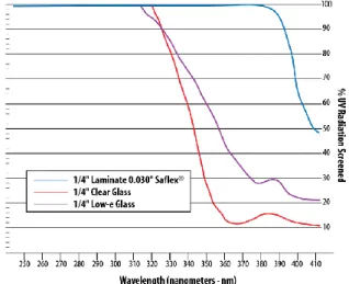
Fig. 27 Sound Trasmission Loss Data (courtesy of Solutia).
Sound Transmission Loss of monolothic glass, laminated glass with Saflex SilentGlass Technology and standard PVB interlayer. Laminated glass configuration: 3mm glass/0.76mm interlayer/ 3mm glass.
Light and solar energy control. Because the amount of energy transferred through glazing impacts the costs of heating, cooling and lighting a building, solar and thermal energy controls must be carefully considered when designing and specifying a glazing system (Fig. 28).
113 CHAPTER 4-GLASS:MATERIALS &PRODUCTS
Fig. 28 Comparative Ultraviolet Screening Performance (courtesy of Solutia)
UV screening performance is defined as the ability of the configuration to screen greater than 99% of UV radiation to 380nm wave length.
By combining various glass types and/or tinted interlayers, laminated glass is reduce heat gain, minimize UV transmission and control visible light and glare. These properties are important in varying degrees to all residential and non-residential buildings. Such solutions are particularly effective when combined in insulating glass units.
Security. Depending on the number of plies of glass, and the number and thickness of interlayers, laminated glass is used in a variety of applications for burglary resistance, physical detention and even bullet resistance. EN ISO 12543-2 for Security Glazing describes test conditions for panels intended to withstand standard categories of bullet penetration resistance. Software programmes have been developed by the interlayer manufactures to assist selection of laminated glass types for burglar, bullet and blast resistant applications.
Bomb Blast resistance. For laboratories, army facilities and any other buildings at risk of accidental or pre-meditated explosion, most efficiently in conjunction with structural bonding to steel frames bolted to the substrate, laminated glasses can contain explosions thereby reducing the risk of damage to property or injury to persons on the exterior. In blast-resistant glazing materials and systems, laminated glass can be used to reduce the hazards associated with an explosion. Laminates made with PVB or SentryGlas® ionoplast interlayers are typically used in window, door, curtain wall, and storefront systems designed to provide a higher level of performance than standard
114 CHAPTER 4-GLASS:MATERIALS &PRODUCTS
systems. Shock tube and arena test results support the use of both PVB and ionoplast interlayers to help manufacture blast-resistant glazing.
Shock tube (Fig. 29) focuses a blast-level pressure wave against a mounted glass sample. Outdoor arena testing (Fig. 30) exposes full-scale facade glazing to an actual explosion.
Fig. 29 Shock tube Testing. Fig. 30 Outdoor arena Testing.
Fire resistance. Multi-layered fire-resistant glasses are made of clear or extra clear float glass, laminated with special transparent intumescent interlayers. When exposed to fire, the pane facing the flames fractures but remains in place, and the interlayer immediately foams up to form a thick, resilient and tough insulating shield that absorbs the energy of the blaze. This takes place at relatively modest temperatures around 120°C, such that protection is provided right from the early stages of a fire.
The classification for fire-rated glasses, in accordance with EN 13501-2, is as follows: CLASSIFICATION REQUIREMENTS
EI Full thermal insulation (basic integrity + thermal insulation) EW Enhanced integrity (basic integrity + reduced heat radiation) E Basic integrity (barrier against smoke, flames and fumes)
Colour. To obtain colour not available in manufacturers’ product ranges, the incorporation of various interlayers in different combinations can produce many composite choices. Colour laminated glass is manufactured using standard clear float glass, or in alternative it is also available in specialist glasses including low iron (crystal clear) and a variety of body tints: blue, green, bronze and grey (Fig. 31). The type and thickness of the glass will have an effect on the colour chosen. Colour laminating can also be combined with other decorative glass products and finishes such as kiln forming, sandblasting and colour coating.
115 CHAPTER 4-GLASS:MATERIALS &PRODUCTS
Fig. 31 Abin Design Studio, International Management Institute, Kolkata, INDIA (Solutia Courtesy).
4.4.1.4SECONDARY MANUFACTURE:INSULATED GLASS UNITS (IGUS)
A typical insulating glass units (IGUs) are basically multiple layered glass panes that have very dry air or inert gas between the glass panes (Fig. 32). The glass panes are hermetically sealed. They are separated around their entire perimeter by a hollow spacer bar, generally between 12 and 20mm thick. A moisture absorbent desiccant is placed in the space bar, which is perforated on the cavity face, to provide a moisture-free air space. The long-term stability of the IGU is determined by the quality of the edge seal. Three different types of insulating glazing can be differentiated according to the edge seal, whereby the first two are seldom manufactured nowadays.
1. WELDED EDGE.
2. SOLDERED EDGE
3. DUAL EDGE SEAL.
Fig. 32 IGU cross section
1. 2. 3.
The entire perimeter of modern IGUs is hermetically sealed with two sealants, the primary being non-setting extruded polyisobutylene (PIB) and the secondary being
116 CHAPTER 4-GLASS:MATERIALS &PRODUCTS
elastomeric (silicone, polysulphide or polyurethane), which is applied under nominal pressure from a dispenser (Fig. 33).
Fig. 33 Cross Section.
Spacer: Spacer performs the role of keeping the
glass panes apart as well acts as a housing for the desiccant.
Desiccant: Or, the drying agent performs the
most important role in an IGU; that of absorbing the moisture from the hermetically sealed space.
Primary sealant: First line of defence for the
hermetic seal.
Secondary Sealant: This sealant is applied on the
outside of the unit. It provides structural strength.
These sealants perform integrally; the primary seal provides a barrier to keep out moisture and retain gas where employed, while the purpose of the secondary seal is to bond the components together, to provide structural rigidity, to withstand the specified wind load and to prevent stresses being transferred to the primary seal by reducing deformation of the units. It is to be stressed that while silicone is waterproof, it has higher vapour permeability than organic sealants, thus it has not been traditionally used as secondary seal in gas-filled units, but argon gas filled units sealed with silicone have proven to be successful and pass the requirements of EN 1279. Polysulphide is vapour resistant and compatible with the majority, if not all, of the gases employed for thermal and acoustic performance enhancement but it is sensitive to ultraviolet light and therefore cannot be exposed to the sun. Its adhesion is also inferior to silicone.
Polyurethane is used only for IGUs where the entire perimeter is fully encapsulated in a framing system. Although highly UV resistant it has limited structural properties and therefore requires beads or pressure plates to secure the glass. Also, since structural adhesion is not a requirement, it is possible to decrease the sealant contact depth to around 4.5mm, thereby economising on material. The minimum recommended depth for silicone edge sealant is 6mm, but for IGUs formed with holes for frameless (bolted) glazing, the depth is increased automatically for the insertion of U-inserts in structural glazing with
117 CHAPTER 4-GLASS:MATERIALS &PRODUCTS
toggles (Fig. 34 and 35). Laminated glass can be used in an insulating glass unit to combine the safety, sound, glass retention and security properties of laminated glass with improved thermal performance.
Fig. 34 Rotule for single and double IGU's, with countersunk holes
Fig. 35 Rotule for single and double IGU's, with straight glass holes
(Courtesy of Faraone)
Aluminium spacer bars are typically clear anodized but when in structural or frameless glazing, especially with semi-transparent or clear double glass, it may be aesthetically preferable for them to be anodized black for edge colour consistency, to eliminate the contrast of the silver against the black of structural silicone. Spacer bars may be also stainless steel. Ideally the spacer bars should be as continuous as possible because each connection is a potential weak point for gas retention and corner keys can provide a prime source of leakage.
Warm edge technology (WET) is a continuing development to improve the thermal performance of the edge of sealed IGUs, focusing on an approximately 63mm width of glass inside the perimeter sight line. There are a number of warm-edge spacer designs available, all of which thermally break the metal-to-glass contact point to some degree, while offering varying levels of structural integrity that may or may not be suitable for commercial applications (Fig. 36 a, b).
118 CHAPTER 4-GLASS:MATERIALS &PRODUCTS
Fig. 36 a, b. Warm Edge Technology.
Warm-edge spacers can significantly reduce heat conduction when compared to conventional aluminium spacers. It aims to add more resistance to heat flow from the warm side to the cold side of the glazing, thereby enhancing both condensation and thermal resistance, hence its use is most appropriate in cold climate conditions. All commercially available annealed, heat-strengthened and fully tempered glass products can be built into an IGU.
The following images (Fig. 37) depict the most common glass configurations and identify the glass surfaces with numbers showing the glass surfaces counting from exterior to interior.
119 CHAPTER 4-GLASS:MATERIALS &PRODUCTS
Double glazing is used in a wide range of applications including: commercial/residential fixed and operable windows, curtain walls, storefronts, sloped/overhead glazing, non-vision (spandrel) locations. There are many benefits of utilizing IGUs:
Improve thermal insulation, therefore energy cost is reduced. Improve internal comfort, both in summer and in winter.
Decrease condensation by providing a thermal barrier between the inside and the outside.
Diminish the effects of fading, since double glazing prevents direct contact with sunlight Reduce unwanted sound transmission, since air inside the IG will prevent the resonance
from passing through.
4.4.2
S
ECONDARY MANUFACTURE:
G
LASSC
OATINGSCoatings are applied to clear glass for the purpose of adding colour for aesthetics, solar control and heat insulation [86]. There have been substantial developments in high performance glass coatings, and they comprise two main categories:
1)HARD COAT AND ON-LINE COATINGS
Hard coatings are applied to the float glass while in a semi-molten state and the process is one of deposition of metal ions by spraying to form a layer that fuses to the surface. Hard coat products have emissivities ranging from 0.15 to 0.2. Pyrolytic coating
process (Fig. 38) deposits a metallic oxide directly onto the glass surface whilst it is still hot.
The coating is effectively “baked-on” to the surface and the resulting coating is very hard and durable. Pyrolytic coatings can be up to 20 times thicker than sputtered coatings (they are still 500 times thinner than a human hair) and the baking process makes them much harder and resistant to wear. Pyrolytic “hard coats” are of medium performance for both solar control and reduced emissivity. They are most economical, corrosion proof, suitable for single glazing, abrasion proof and no edge deletion is necessary for double or structural glazing; they are post-temperable and have a good colour retention (Fig. 39).
120 CHAPTER 4-GLASS:MATERIALS &PRODUCTS
Fig. 38 Pyrolitic process (Courtesy of Tangram UK) Fig. 39 "Hard coat" glass (Courtesy of Pilkington).
For instance, on-line coated low-reflective glasses are produced: the low-reflective coating on one surface reduces visible light reflectance and allows more visible light to pass through, when compared to clear float glass (8% light reflectance as standard). Two of those panels can be combined in a LSG with low-reflective coatings on surfaces 1 and 4 (both outer surfaces of the laminated glass), which reduces interior and exterior visible light reflectance to around 2%. As a consequence, views from both inside and out are clear, un-obscured and virtually reflection-free. Furthermore, it provides protection from UV radiation (UVA and UVB) by blocking over 99% of UV transmittance, helping to reduce fading of the contents and interiors of a building.
However, the merit of “hard coat” products is limited by inherently small variety of colours and higher U-values.
2)SOFT COAT AND OFF-LINE COATINGS
Soft coatings are applied by a sputter process of deposition of silver, stainless steel, chrome, titanium, tin, zinc and silica nitride by means of ionic transfer through a vacuum on to fresh float glass (maximum of 6 months old). Sputtering uses a vacuum chamber to put several layers of coating on the basic glass and the total thickness of the coatings is around ten thousand times thinner than a human hair. The process, otherwise known as magnetron
sputtering vapour deposition (MSVD) is sometimes referred to as cathodic vapour
deposition. During the process (Fig. 40), the material to be sputtered is loaded in a high voltage electric circuit, which is followed by the feeding of process gas into vacuum chamber, where plasma is formed. An ion discharge takes place inside the chamber, these positive charged ions gets attracted and collide with the material to be sputtered.
121 CHAPTER 4-GLASS:MATERIALS &PRODUCTS
This process happens at a very high speed and atoms of the material sputtered gets ejected, which gets accumulated on the glass below.
Fig. 40 Magnetronic process (Courtesy of Tangram UK)
Soft coat products can have emissivity ranging from 0.05 to 0.1 compared to uncoated glass that has a typical emissivity of 0.89. This means that “soft coat” products will reflect between 95% and 90% of the long-wavelength radiant energy from the surface where uncoated glass will only reflect 11% of the radiant energy received by the surface. Sputtered coatings are generally pre-temperable only, thus cutting to size notching and drilling must be done first; they must be protected from humidity and contact [86].
Soft coat glasses are generally used in double glazed units, with the coated surface at position 2 or 3, so that the coating is kept protected from peeling off. With the advance in technology, soft coat glasses are now made which can also be used in monolithic form (single glazed) with much improved life for the coating, but still the life of the coating cannot match with that of hard coat glass in monolithic applications.
Within the soft coating category, there are three main classifications:
LOW EMISSIVITY
(LOW-E) GLASS
Low-emissivity glass consists of a float glass on which a high performance coating is applied, due to increase the normal emissivity of the material and to reduce the losses by radiation (Fig. 41). Using low-E substances, values of emissivity of 0.01 (soft coating) can be reached, while the normal emissivity of glass is 0.89. Therefore, the low-E coating allows to maintain a high light transmittance and, at the same time, to reflect radiant infrared energy, proving thermal insulation: thus, the radiant