Chapter 5 The assembly microfactory of the PRIN project
Chapter 5
The assembly microfactory of the PRIN Project
5.1 Introduction
In this Chapter the microassembly system developed within the Italian Research PRIN Project “Development of innovative technologies for the assembly of hybrid microproducts” is shown.
In § 5.2 and § 5.3 the aim and the strategy used to develop the project are described. In § 5.4 the devices and the various assembly tasks considered are explained and it is shown how the systems shown in Chapter 4 are integrated in the microassembly system. Finally, in § 5.5 the tasks performed until now and the assembly system in progress are explained.
5.2 The Prin project
The project 2006-2007 “Development of innovative technologies for the assembly of hybrid microproducts” is a project co financed by the Italian Ministry of the University and the Research (MIUR) and involves five Italian Universities (Pisa, Genova, Padova, Napoli, Torino).
The main goal of the project is to develop, innovate and integrate some technologies and methodologies suitable for assembling hybrid microproducts in order to obtain an easy, economic and robust assembly of microcomponents. These technologies are developed throughout the design and realization of some prototypical devices and of various systems for controlling and measuring, which are all integrated in the Assembly Microfactory of the project
The technologies considered within this project are those needed in the microfactory concept (please refer to § 2.2.4) for a correct and rational realization of the assembly operations: Microhandling (Pisa), Microjoining through Laser Micro Welding (Napoli), Measurement (Padova), On-line Control (Genova), Design for MicroAssembly and the study of new Tolerancing standards in the micro field (Torino). These technologies are studied in order to define their application fields, key parameters, possible improvements, systems for increasing the process reliability and controllability.
The development of the project is based on a meaningful benchmark, including components of different materials and with at least one dimension less than one millimeter, on which it is possible to test and integrate the different technologies. The benchmark is assembled, controlled and measured as much as possible, by using the developed devices and technologies. Because the approach to the development of
Microhandling devices for the assembly of Hybrid Microproducts
implementing a series of rules of Design for MicroAssembly that help to consider assembly and control issues since the conceptual phase.
5.3 Choice of the benchmark, assembly strategy and tasks
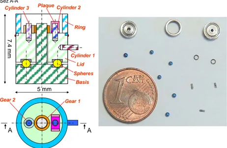
The selected meaningful benchmark is an “ad hoc” product that allows the depth development of the technologies involved in the project. Actually the main goal of the project is not assembling the particular hybrid products but developing the technologies. The designed benchmark and its components are shown in Figure 1.Gear 1 Gear 2 A 7. 4 m m Spheres Basis Lid Cylinder 1 Cylinder 2 Cylinder 3 Ring Plaque 5 mm Sez A-A A
Figure 1: The benchmark and its components.
The selected assembly tasks and the features of the benchmark components are shown in Table 1-2.
TABLE OF THE COMPONENTS
ri bas lid pla ge 2 ge 1 cyl 1-2-3 sph Code Ring Basis Lid Plaque Gear 2 Gear 1 Cylinder 1-2-3 Sphere
Component Dimension Material
steel d:0.5mm ; h:1.5mm steel: AISI 304 d:5mm ; h:2mm steel: AISI 304 d:5mm ; h:3mm steel: AISI 304 steel: AISI 304 steel: AISI 304 steel: AISI 304 steel d:5mm ; h:2.2 mm l:1.6 ; h:1.2 di:0.6 de:1 ; h:0.8 di:1.1 de:1.5 ; h:0.8 d: 0.8 mm
TABLE OF THE TASKS
G Gluing H Welding F Forcing E D C B A Code Grasping/Orienting/Horizontal inserting Grasping/Horizontal inserting Grasping/Orienting/Vertical inserting Grasping/Vertical inserting Grasping/Releasing Task
Chapter 5 The assembly microfactory of the PRIN project
These components and assembly tasks are classical microparts and operations considered in the microassembly of hybrid microproducts [1]. Some of the microparts of the benchmark have been bought on the market (Spheres and Cylinders) while the other ones have been designed by the research group of Pisa and realized by Napoli (Plaque and Gears) and Pisa (Lid, Basis and Ring).
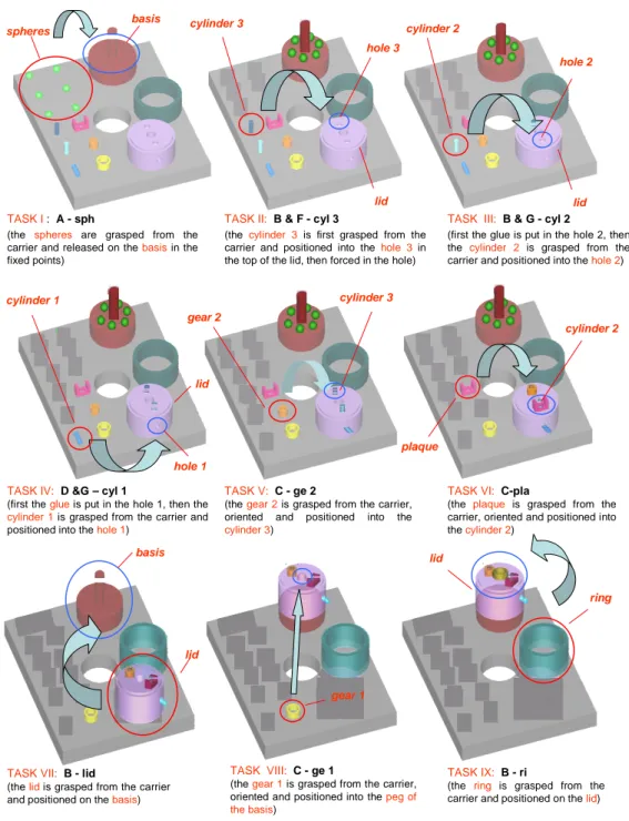
The assembly tasks that allow the benchmark to be completely assembled are shown in Figure 2. In this Figure the tasks and the components are reported by means of the symbols used in Tables 1-2, then briefly explained (for more information please refer to § 5.4).
Microhandling devices for the assembly of Hybrid Microproducts
basis spheres
TASK I: A - sph
(the spheres are grasped from the carrier and released on the basisin the fixed points)
TASK II: B & F - cyl 3
(the cylinder 3is first grasped from the carrier and positioned into the hole 3 in the top of the lid, then forced in the hole)
cylinder 2
lid hole 2
TASK III: B & G - cyl 2
(first the glue is put in the hole 2, then the cylinder 2 is grasped from the carrier and positioned into the hole 2) cylinder 3 lid hole 3 gear 2 cylinder 3 TASK V: C - ge 2
(the gear 2is grasped from the carrier, oriented and positioned into the
cylinder 3) cylinder 1
lid
hole 1
TASK IV: D &G – cyl 1
(first the glueis put in the hole 1, then the
cylinder 1is grasped from the carrier and positioned into the hole 1)
plaque
cylinder 2
TASK VI: C-pla
(the plaque is grasped from the carrier, oriented and positioned into the cylinder 2)
TASK VII: B - lid
(the lidis grasped from the carrier and positioned on the basis)
TASK VIII: C - ge 1
(the gear 1is grasped from the carrier, oriented and positioned into the peg of the basis)
TASK IX: B - ri
(the ring is grasped from the carrier and positioned on the lid) lid
basis
gear 1
lid
ring
Chapter 5 The assembly microfactory of the PRIN project
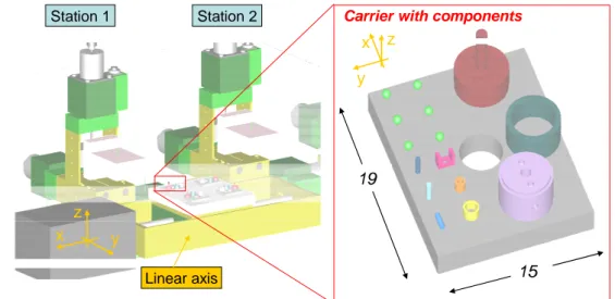
The assembly strategy of the benchmark makes use of a controlled linear axis with a carrier and different assembly stations equipped with various grippers. The components of the benchmark are loaded onto a carrier that moves from an assembly station to the next one until the product is completely assembled (Figure 3).
19
15 Station 2
Station 1 Carrier with components
Linear axis
x y
z
y x z
Figure 3: The assembly strategy and the carrier with the benchmark components. This assembly strategy has been selected on the basis of the research about the state of the art on microfactories (please refer to § 2.2.4). The approach of a controlled linear axis that supports a carrier moving from an assembly place to other ones allows the control of the assembly stations only and gives versatility to the system. Actually, a general purpose design of the carrier and the assembly stations permits to assembly different kind of hybrid microproducts by simply modifying the assembly sequences and the position of components onto the carrier. When the products change significantly in terms of components and assembly tasks, a new layout of the stations and different grippers or joining device can be adopted to fulfill the new production. In this sense, a modular conception of the stations in terms of DOF and end-effectors is required. So, each station is equipped with on-line control and consists of a multi DOF programmable manipulator able to support different kinds of grippers. The on-line control is carried out with vision systems by means of various cameras for each station. In particular the approach is to make use of a camera that has a global vision of the carrier and other cameras with a limited observed area to control with high magnification and resolution only the part of the carrier where the assembly task takes place.
Microhandling devices for the assembly of Hybrid Microproducts
5.4 The devices of the assembly system and the simulation
In the benchmark assembly process, two groups of tasks are required: the loading of the mobile carrier and the assembly operations. In order to fulfill these tasks, various devices have been selected and simulations [2] have been carried out to test the operations, the assembly sequence and possible layouts of the assembly system.
5.4.1
The loading of the carrier
The carrier is 19x15mm2 in size and contains all the benchmark components (Figure 3). Some constrains (i.e. little hole for spheres or slots for cylinders) have to be used to avoid unwanted shift of the components during the carrier movement.
A commercial linear axis has been selected to support the tray and to move it among the assembly stations (Figure 4).
100
270 50
50 Figure 4: The linear axis supporting the carrier.
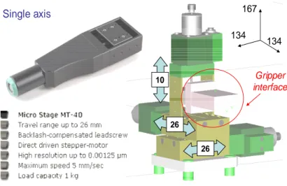
The carrier is supposed to be loaded with the benchmark components in various loading stations. The components are first transported and arranged near the loading stations, then moved on the carrier by means of the devices described in Chapter 4 and other commercial devices. A programmable 3 DOF commercial manipulator has been selected to support (through an interface) the various grippers used to pick the benchmark microcomponents (the spheres, the cylinders and the gears) and to place them on the carrier. The same manipulator is used to support the end-effectors used for the assembly tasks. This manipulator has been chosen basing on some main constrains: 3 DOF, workspace equal at least to the carrier, minimum size, repeatability precision of 1µm, low cost. A wide market investigation of commercial manipulators has been done. The chosen manipulator is the MICOS Micro Stage MT-40 (Figure 5): it is the best one that satisfies the requested performance.
Chapter 5 The assembly microfactory of the PRIN project Single axis 10 26 26 Gripper interface 134 134 167
Figure 5: The selected 3 DOF manipulator.
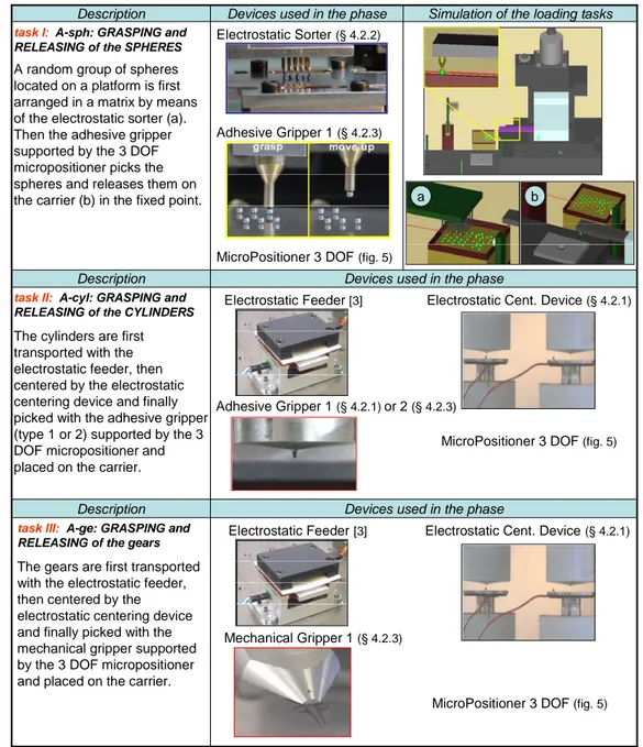
The tasks and the devices selected to load the carrier with the components and some of the significant frames of the simulations are shown in Table 3 and 4. In Table 3 it is shown how it is possible to upload the microcomponents of the benchmark by means of the developed handling device shown in Chapter 4 and other devices developed within the microassembly research group at DIMNP.
Microhandling devices for the assembly of Hybrid Microproducts
Devices used in the phase Description
Devices used in the phase Description
Simulation of the loading tasks Devices used in the phase
Description
Electrostatic Feeder[3] Electrostatic Cent. Device(§ 4.2.1)
Mechanical Gripper 1 (§ 4.2.3)
MicroPositioner 3 DOF (fig. 5)
task III: A-ge: GRASPING and RELEASING of the gears
The gears are first transported with the electrostatic feeder, then centered by the electrostatic centering device and finally picked with the mechanical gripper supported by the 3 DOF micropositioner and placed on the carrier.
Electrostatic Feeder [3] Electrostatic Cent. Device(§ 4.2.1)
Adhesive Gripper 1 (§ 4.2.1)or 2 (§ 4.2.3)
MicroPositioner 3 DOF (fig. 5)
task II: A-cyl: GRASPING and RELEASING of the CYLINDERS
The cylinders are first transported with the electrostatic feeder, then centered by the electrostatic centering device and finally picked with the adhesive gripper (type 1 or 2) supported by the 3 DOF micropositioner and placed on the carrier.
Electrostatic Sorter(§ 4.2.2)
Adhesive Gripper 1(§ 4.2.3)
MicroPositioner 3 DOF(fig. 5)
task I: A-sph: GRASPING and RELEASING of the SPHERES
A random group of spheres located on a platform is first arranged in a matrix by means of the electrostatic sorter (a). Then the adhesive gripper supported by the 3 DOF micropositioner picks the spheres and releases them on
the carrier (b) in the fixed point. a b
Chapter 5 The assembly microfactory of the PRIN project
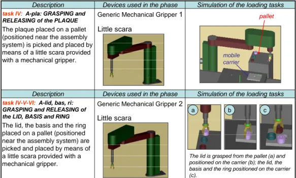
On the contrary, the benchmark macrocomponents (the ring, the basis, the lid and the plaque) are manually positioned on the carrier. In alternative, these components could be first positioned on a pallet and then moved on the mobile carrier by means of commercial robots equipped with mechanical gripper (e.g. little SCARA with mechanical grippers as shown in Table 4).
Simulation of the loading tasks Devices used in the phase
Description
Simulation of the loading tasks Devices used in the phase
Description
Generic Mechanical Gripper2 Little scara
task IV-V-VI: A-lid, bas, ri: GRASPING and RELEASING of the LID, BASIS and RING
The lid, the basis and the ring placed on a pallet (positioned near the assembly system) are picked and placed by means of a little scara provided with a mechanical gripper.
Generic Mechanical Gripper1 Little scara
task IV: A-pla: GRASPING and RELEASING of the PLAQUE
The plaque placed on a pallet (positioned near the assembly system) is picked and placed by means of a little scara provided with a mechanical gripper.
pallet
mobile carrier
The lid is grasped from the pallet (a) and positioned on the carrier (b); the lid, the basis and the ring positioned on the carrier (c).
a b c
Table 4: Tasks and hypothetical devices for loading automatically macrocomponents.
5.4.2
The assembly tasks
With regard to the assembly stations, they have to be equipped with manipulators that support grippers able to pick the benchmark components from the carrier and place them in the preset positions. So the features of the manipulators and grippers depend on both the assembly tasks and the characteristics of components to be handled.
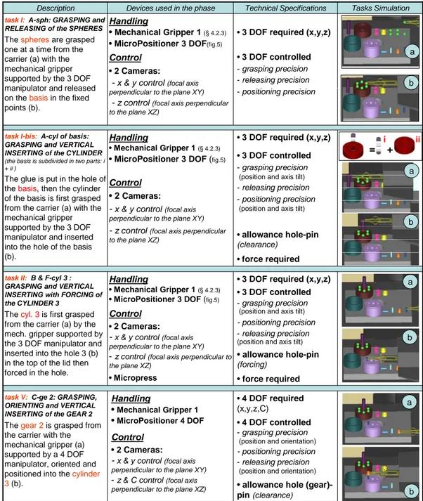
The technical specifications of the assembly tasks have been analyzed in order to select the handling and control devices required to fulfill the operations as shown in Table 5, 6, 7. In these tables, the number of the task refers to those used in Figure 2, but their order is based on the assembly sequence found out with the simulation. Actually, the simulation has shown an optimal assembly sequence different from that assumed in Figure 2.
Microhandling devices for the assembly of Hybrid Microproducts
•3 DOF required (x,y,z) •3 DOF controlled - grasping precision
(position and axis tilt) - positioning precision - releasing precision
(position and axis tilt)
• allowance hole-pin
(forcing)
• force required
Handling
• Mechanical Gripper 1(§ 4.2.3) • MicroPositioner 3 DOF (fig.5)
Control •2 Cameras:
-x & y control(focal axis perpendicular to the plane XY)
-z control(focal axis perpendicular to the plane XZ)
• Micropress task II:B & F-cyl 3 :
GRASPING and VERTICAL INSERTING with FORCING of the CYLINDER 3
The cyl. 3is first grasped from the carrier (a) by the mech. gripper supported by the 3 DOF manipulator and inserted into the hole 3 (b) in the top of the lid then forced in the hole.
•3 DOF required (x,y,z) •3 DOF controlled - grasping precision
(position and axis tilt)
- releasing precision - positioning precision
(position and axis tilt)
•allowance hole-pin (clearance)
•force required Handling
• Mechanical Gripper 1(§ 4.2.3) • MicroPositioner 3 DOF (fig.5)
Control
• 2 Cameras:
- x & y control(focal axis perpendicular to the plane XY)
- z control(focal axis perpendicular to the plane XZ)
task I-bis: A-cyl of basis: GRASPING and VERTICAL INSERTING of the CYLINDER
(the basis is subdivided in two parts: i + ii )
The glue is put in the hole of the basis, then the cylinder of the basis is first grasped from the carrier (a) with the mechanical gripper supported by the 3 DOF manipulator and inserted into the hole of the basis (b).
•4 DOF required
(x,y,z,C)
•4 DOF controlled - grasping precision
(position and orientation) - positioning precision - releasing precision
(position and orientation)
• allowance hole
(gear)-pin(clearance)
•3 DOF required (x,y,z)
•3 DOF controlled - grasping precision - releasing precision - positioning precision
Technical Specifications Tasks Simulation Devices used in the phase
Description Handling •Mechanical Gripper 1 •MicroPositioner 4 DOF Control • 2 Cameras: -x & y control(focal axis perpendicular to the plane XY)
-z & C control(focal axis perpendicular to the plane XZ)
task V: C-ge 2: GRASPING, ORIENTING and VERTICAL INSERTING of the GEAR 2
The gear 2is grasped from
the carrier with the mechanical gripper (a) supported by a 4 DOF manipulator, oriented and positioned into the cylinder
3 (b). Handling • Mechanical Gripper 1 (§ 4.2.3) • MicroPositioner 3 DOF(fig.5) Control • 2 Cameras:
- x & y control(focal axis perpendicular to the plane XY)
- z control(focal axis perpendicular to the plane XZ)
task I: A-sph: GRASPING and RELEASING of the SPHERES
The spheresare grasped
one at a time from the carrier (a) with the mechanical gripper supported by the 3 DOF manipulator and released on the basisin the fixed points (b). a b a b a b a b = + ii i
Chapter 5 The assembly microfactory of the PRIN project
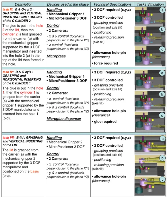
• 3 DOF required (x,y,z) • 3 DOF controlled - grasping precision
(position and axis tilt)
- positioning - releasing precision (axis tilt) • allowance hole-pin (clearance) • glue required Handling • Mechanical Gripper 1 • MicroPositioner 3 DOF Control • 2 Cameras:
-x control(focal axis perpendicular to the plane XY) -y & z control(focal axis perpendicular to the plane YZ) Microglue dispenser task IV: D & G-cyl1 :
GRASPING and
HORIZONTAL INSERTING of the CYLINDER 1
The glue is put in the hole 1, then the cylinder 1is grasped from the carrier (a) with the mechanical gripper 1 supported by the 3 DOF manipulator and inserted into the hole 1 (b-c).
• 3 DOF required (x,y,z) • 3 DOF controlled - grasping precision
(position and axis tilt)
- positioning - releasing precision (axis tilt) • allowance hole-pin (clearance) Handling • Mechanical Gripper 2 • MicroPositioner 3 DOF Control • 2 Cameras:
-x control(focal axis perpendicular to the plane XY) -y & z control(focal axis perpendicular to the plane YZ)
task VII: B-lid : GRASPING
and VERTICAL INSERTING of the LID
The lidis grasped from the carrier (a) with the mechanical gripper 2 supported by the 3 DOF manipulator and positioned on the basis
(b-c).
• 3 DOF required (x,y,z) • 3 DOF controlled - grasping precision
(position and axis tilt)
- positioning - releasing precision (axis tilt) • allowance hole-pin (clearance) • force required Handling • Mechanical Gripper 1 • MicroPositioner 3 DOF Control • 2 Cameras:
-x & y control(focal axis perpendicular to the plane XY) -z control(focal axis perpendicular to the plane XZ) Micropress
task III: B & G-cyl 2 : GRASPING and VERTICAL INSERTING with FORCING of the CYLINDER 2
The glue is put in the hole 2of the lid, then the cylinder 2is first grasped from the carrier (a) with the mechanical gripper supported by the 3 DOF manipulator and inserted into the hole 2 (c) in the top of the lid then forced in the hole.
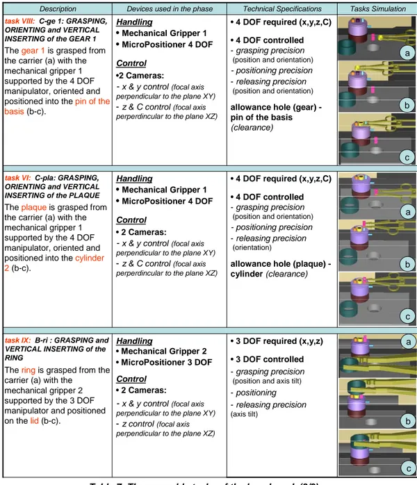
Technical Specifications Tasks Simulation Devices used in the phase
Description a c b a c b a c b
Microhandling devices for the assembly of Hybrid Microproducts
• 4 DOF required (x,y,z,C) • 4 DOF controlled - grasping precision
(position and orientation)
- positioning precision - releasing precision
(orientation)
allowance hole (plaque) -cylinder (clearance) Handling •Mechanical Gripper 1 •MicroPositioner 4 DOF Control • 2 Cameras:
-x & y control(focal axis perpendicular to the plane XY) -z & C control(focal axis perperdincular to the plane XZ) task VI: C-pla: GRASPING,
ORIENTING and VERTICAL INSERTING of the PLAQUE
The plaqueis grasped from
the carrier (a) with the mechanical gripper 1 supported by the 4 DOF manipulator, oriented and positioned into the cylinder 2(b-c).
• 4 DOF required (x,y,z,C) • 4 DOF controlled - grasping precision
(position and orientation)
- positioning precision - releasing precision
(position and orientation) allowance hole (gear) -pin of the basis
(clearance) Handling •Mechanical Gripper 1 •MicroPositioner 4 DOF Control •2 Cameras:
-x & y control(focal axis perpendicular to the plane XY) -z & C control(focal axis perperdincular to the plane XZ) task VIII: C-ge 1: GRASPING,
ORIENTING and VERTICAL INSERTING of the GEAR 1
The gear 1is grasped from
the carrier (a) with the mechanical gripper 1 supported by the 4 DOF manipulator, oriented and positioned into the pin of the
basis (b-c).
• 3 DOF required (x,y,z) • 3 DOF controlled - grasping precision
(position and axis tilt)
- positioning - releasing precision
(axis tilt)
Technical Specifications Tasks Simulation Devices used in the phase
Description Handling • Mechanical Gripper 2 • MicroPositioner 3 DOF Control • 2 Cameras:
-x & y control(focal axis perpendicular to the plane XY) -z control(focal axis perpendicular to the plane XZ) task IX: B-ri : GRASPING and
VERTICAL INSERTING of the RING
The ringis grasped from the carrier (a) with the
mechanical gripper 2 supported by the 3 DOF manipulator and positioned on the lid(b-c). a c b a c b a c b
Chapter 5 The assembly microfactory of the PRIN project
In comparison with the assembly sequence assumed in Figure 2 the differences emerged from the analysis are essentially two. The first one is that the basis has been subdivided in two parts in order to simplify the positioning of the spheres on the basis. Thus, a new assembly task (“1 bis” in Table 5) is required. The second variation is the different assembly sequence caused by an easier handling and positioning of various benchmark components.
5.5 The microfactory developed within the project
At the Department of Mechanical, Nuclear and Production Engineering (DIMNP) of the University of Pisa, the assembly microfactory of the benchmark is a work in progress (Figure 6). Since humidity (please refer to § 2.1.1) limits the use of handling devices in microdomain, a controlled environment where it is possible to maintain a humidity level lower than 30% has been designed and realized: the microfactory is inserted into this controlled environment (Figure 6).
This microfactory (Figure 6) consists, at the moment, of the linear axis with the carrier, an assembly station with the 3 DOF manipulator (able to support the mechanical and the adhesive gripper described in § 4.2.3), the electrostatic sorting systems (please refer to § 4.2.2), the centering device § 4.2.1) and a camera with macro lens. This layout permits to carry out some of the loading and assembly tasks as described in Table 3 (for the loading of the carrier) and in Table 5,6,7 (for the assembly of the benchmark). Up to now only a few of these operations have been performed with off line control by simply observing the scene with the camera. The automatic assembly of the benchmark by on line control tasks will be completed before the end of the 2007.
In the following § 5.5.1 - 5.5.2 the operations carried out so far are described.
Electrostatic centering Electrostatic sorting 3 DOF micromanipulator Linear axis Microgripper Carrier with components Camera with Macro lens Controlled environment
Microhandling devices for the assembly of Hybrid Microproducts
5.5.1 The loading of the tray
Task I: A-sph: GRASPING and RELEASING of the SPHERES
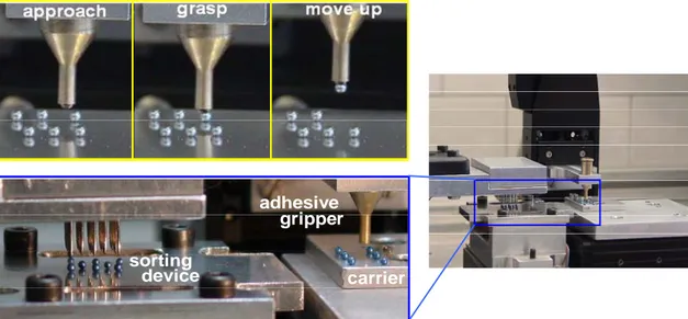
As described in Table 3 (task 1), a random group of spheres is first arranged in a matrix by means of the electrostatic sorter (§ 4.2.2), then the adhesive gripper (§ 4.2.3), supported by the 3 DOF micropositioner, picks the spheres and releases them on the carrier in the fixed point (Figure 7).
sorting
adhesive
carrier device
gripper
Figure 7: Loading of the spheres on the tray: the spheres are first arranged in a matrix by the electrostatic sorter, then grasped and released by the adhesive gripper.
5.5.2
The assembly tasks
Depending on the task, the 3 DOF manipulator is equipped with the required gripper as theoretical studies in Table 5,6,7.
task I: A-sph: GRASPING and RELEASING of the SPHERES
As described in Table 5 (task 1), the spheres are grasped one at a time from the carrier with the mechanical gripper piezo actuated supported by the 3 DOF manipulator and released on the basis in the fixed points Figure 8.As tested in the simulation, the spheres have to be released on the basis following a particular sequence to avoid collisions between the gripper and the other spheres already positioned.
Chapter 5 The assembly microfactory of the PRIN project carrier device sorting adhesive gripper
Figure 8: The 3 DOF manipulator equipped with the mechanical gripper piezo actuated; the grasping of the spheres from the tray and their releasing on the basis of the benchmark.
Microhandling devices for the assembly of Hybrid Microproducts
References
[1] Geiger, M., Egerer, E., Enfel, U., 2002, Cross Transport in Multi-Station Former for Microparts, Production Engineering, IX/1, pp. 101-104.
[2] Consani, L., 2007, Degree thesis, Department of Mechanical, Nuclear and Production Engineering of the University of Pisa.
[3] Fantoni, G., Santochi, M., 2005, A modular contactless feeder for microparts, Annals of the CIRP, vol. 54/1.