Section 1 - Notes on composite floors with profiled steel decking and cast-in-situ
concrete
1.1 Introduction
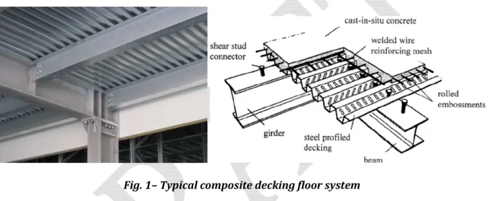
Composite deck slab floors are gaining wide acceptance in many countries as they lend themselves to faster, lighter and economical construction in buildings. In steel-concrete composite structures it is typical to adopt thin-walled steel elements to realize the floor. In fact, in a composite building, the most usual type of floor is realized with a profiled steel sheeting finished with cast-in-situ concrete, a steel mesh and, eventually, steel rebars, leaning on a grid of steel beams (referred as primary beams if connecting the columns or secondary if connecting relatively the primary beams).
Fig. 1– Typical composite decking floor system
The steel-concrete composite slab is therefore composed by a profiled steel sheeting and a concrete slab. It constitutes the floor only, when the composite slab is not connected to the underlying beam. Conversely, it may be used also to improve stiffness and strength of the steel members, taking advantage of the composite action, when the floor is mechanically fastened to the steel beams (e.g. with studs or other devices).
Fig. 2 – Friction interlock and mechanical interlock
The role of the steel decking is twofold. Initially, in the construction phase, it allows to cast concrete directly on site (without propping or with a limited number of supports) and, basically, it works as a
formwork. Therefore, it is normally realized starting from a flat coil which is profiled to provide to the steel section, a stiffness and resistance adequate to support the construction loads with a limited deflection (e.g. the concrete and/or the machinery weight). Subsequently, after that concrete is completely cured (conventionally after 28 days), concrete and steel realize a monolithic cross-section, in which the connection between profiled steel sheeting and concrete is assured mainly by adhesion or friction. In this second phase, the steel sheeting acts as a tension reinforcement for sagging bending moment. The only additional steel that is needed in practice is normally provided to take care for shrinkage, to limit cracking, for temperature effects and, in case of continuous slabs, it has to be provided to resist hogging bending moments.
Fig. 3 – Typical patterns of embossments in a steel decking
In the typical situations, no mechanical devices are employed to connect steel and concrete in a composite decking, while the connection in most of the cases is improved by embossing the profiled sheeting. This increases the mechanical interlocking arising between decking and concrete.
Fig. 4 – Realization in the shop of a decking starting from the coil through a profiling machine The steel grades adopted in practice to realize the profiled sheeting are continuously hot-dip coated steel strip and sheet products galvanized directly in the factory obeying to the EN10346:2015 standard. The mechanical properties of such steels are classified on the base of yield strength, ultimate resistance and elongation at break, as reported in the next table.
Tab. 1 – Steel grades typically adopted to realize profiled steel sheeting
1.1.1 Technological aspects The commercial dimensions of
1.2 Behaviour of the composite decking in the 1st construction phase – concrete casting
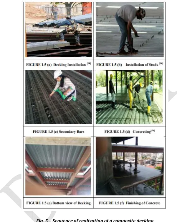
Fig. 5 – Sequence of realization of a composite decking
In the initial phase, when the concrete is cast on site, the steel sheeting must resist to the gravity loads deriving from the weight of concrete and machinery. At this stage, as abovesaid, the steel decking acts as a formwork and must have a resistance and stiffness sufficient to sustain the gravity and live loads typically present in the construction site when concrete is cast in place.
The cross-section of the metal decking is typically thin-walled. This means that the slenderness of the individual plates composing the cross-section is such that local buckling phenomena may occur for
levels of stress lower than the yield point of the base material (the typical thickness of a profiled steel decking ranges from 0.8 to 1.5 mm and consequently the width/thickness ratio of the individual plates composing the cross-section is rather large). This type of buckling is normally called local, because the length of the buckle is comparable to the cross-section size. In thin-walled elements, typically, local buckling phenomena may arise in bending, compression, shear or bearing and, therefore, the occurrence of local buckling is one of the major design considerations. In this regard, when performing the check of the steel decking in bending it is very important to account for the possibility of local buckling of the compressed parts of the cross-section reducing properly the full elastic strength according to the effective-width methodology codified in Eurocode 3 part 1.3 and 1.5. Similarly, when checking the decking in the construction phase, it is very important to control that the shear buckling resistance of the sheeting webs is sufficient to avoid the premature failure of the cross-section plates at the supports.
Fig. 6 – Buckling response of bars, cylindrical shells and plates
It has to be preliminarily underlined that not always elastic buckling of thin plates, such as those composing the cross-section of the steel decking, results directly in a failure because, in most of the cases, the buckling mechanism is stable. This means that after buckling initiation, typically the cross-section can still carry increasing values of the loads. This is due to the redistribution of the internal
actions that occurs after buckling initiation from the central part of the plate to the sides. Thanks to this secondary action, the plate can continue to carry load after buckling initiation although with a reduced stiffness.
Such a post-buckling behaviour obviously differs from the classical Euler flexural buckling of a column and can be easily visualized taking advantage of a strut and tie grid idealization of the plate. If we imagine the plate as a grid of vertical compressed struts and horizontal simply supported ties, it should be easy to understand that if the struts are disconnected each other, the central ones will buckle before the sides ones. This is mainly due to the constraining action provided by the horizontal ties which prevent the contemporary failure of all the struts for the same value of the theoretical critical buckling stress. Therefore, while the central part of the plate will buckle before, the lateral sides of the plate will be able to give to the plate a post-buckling resistance, resulting into a stable failure mechanism.
Fig. 7 – Strut and tie schematization of a plate
This simple example explains also what the shape of the stresses in the pre-buckling and post-buckling phases is. In fact, in the pre-buckling phase the stresses are uniformly distributed, while after buckling initiation they become non-uniform and concentrate near the supported edges. This is mainly due to the membrane effect provided by the horizontal ties of the plate. Afterwards, the plate yields and starts to fail due to material crushing.
Fig. 8 – Stresses in the plate in the pre-buckling and post-buckling phases
1.2.1 Buckling of plates Eulerian buckling
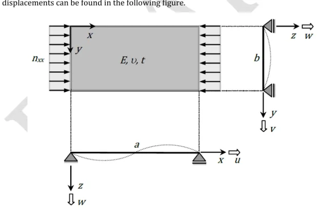
The critical Euler plate buckling stress (σcr) is the starting point for every method, since it is used to define the relative plate slenderness. It is the stress level at which flexural buckling occurs in a perfect plate. No imperfections are taken into account, and linear elastic material is assumed. The critical stress can be derived in many ways, for instance via direct equilibrium equations or a virtual work method. Subsequently, a potential energy method is used. The definition of the plate, its properties, relevant axis and displacements can be found in the following figure.
Fig. 9 – Definition of a single plate The most general form of the potential energy equation is:
In other words, the elastic potential energy is the half of strain times stress, summed up over every direction and integrated over the entire structure. This equals to the area under a linear stress-strain curve. The potential energy lost by the load is equal to the work done by the load, which is force times displacement. For a minimum of potential energy for every δu it should hold that:
+ − > 0
Fig. 10 – Effect of bending in the two directions
Fig. 11 – Effect of twisting
In this case the elastic potential energy is due to bending of the plate. For a very small plate part with dimensions dx and dy loaded by distributed bending moments along its edges the following holds for bending in x, bending in y and twisting:
=12 ! " # =12 ! " $% &' %(& () ** =12 !** ( #*=12 !** ( $% &' %"& ") * =12 ! * " + =12 ! * " $% &' %(%" () * =12 ! * ( + =12 ! * ( $% &' %(%" ") Therefore: =12 $! % &' %(&+12 !**% &' %"& + 2! * % &' %(%") ( "
For relating moment to curvature these expressions are available from general plate theory: ! = , $%%(&'& + -%%"&'&)
!** = , $%%"&'& + -%%(&'&) ! *= , 1 − - %(%"%&'
, =12 1 − -./ &
Adding the three components, integrating over the area of the plate and substituting the moments we get the total elastic potential energy of the plate:
=,2 0 0 1$%%(&'& + -%%"&'&) &
− 2 1 − - 2%%(&'&%%"&'& − $%(%")%&' &34 ( " 5
6 5
The potential energy provided by the load is given by:
= 78 = 79 . 0 12 :%'%(;& (
The next step is to assume a displaced shape due to the buckling of the plate. One half sine wave in y direction and m half waves in x direction are used. This equates to:
' = <=>8?@(A =>8@"7 ? = 1,2,3 … … > Deriving w, substituting and simplifying, the elastic potential energy is derived:
=,@8 <FA7 &HI? A J
&
+ :17;&K &
Similarly, the potential energy of the load can be derived: =79 .?8A &@&<& Therefore, the total potential energy of the structure is:
= − =,@8 <FA7 &HI? A J
&
+ :17;&K &
− 79 8A.?&@&<&
The minimum of the potential energy can be found when the first order of variation is set to zero:
< = 2<,@ FA7 8 HI?A J & + :17;&K & − 2<79 8A.?&@&= 0 This implies that the critical buckling load is equal to:
9 , L =12 1 − -MN@&& 7/. & '>.ℎ: MN = HI?R J + IR7J K &
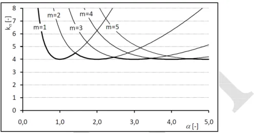
This expression for the elastic critical buckling stress can be applied for all types of plates. The factor MN is called buckling coefficient and it is used to consider the influence of the load case, support conditions and aspect ratio. The here derived buckling factor is valid for a simply supported plate, loaded by pure compression. In annex an extract from the book “aircraft structural analysis” describing in detail the theories of shells and plates as well as all the steps required to define the potential energy previously given, is reported.
Fig. 12 – Effect of the aspect ratio over the buckling factor
In many design codes the aspect ratio is not taken into account in the plate buckling calculations. For a simply supported plate in compression it is taken as 4.0, since the error made is relatively small and on the safe side.
The critical buckling stress could be directly used into a reduced stress method. Nevertheless, it is common practice to define a reduction factor:
TL = 9L7. = UV* 'ℎWXW U =9VL *
Starting from the definition of U, also the plate relative slenderness can be defined as: U =9VL * = 1 Y& → Y = [ V* 9L
The term Y\] is known as the Euler hyperbola. By repeating the same procedure with different constraints or actions, the following coefficients can be defined (other situations are obviously possible, the background knowledge can be easily found in technical literature):
Tab. 2 – Typical values of the buckling factors for frequent cases
kσ Supports on all sides
(Internal element)
Supports on 3 sides (Outstand element)
Compression 4 0.13
Von Karman approach
Many researchers showed that the actual ultimate carrying capacity is much larger than the critical load. This is most obvious with slender plates. Stockier plates have an ultimate load based on yielding, which can be smaller than the critical plate buckling load. Slender plates on the other hand show an extra post-buckling capacity after passing the initial post-buckling load.
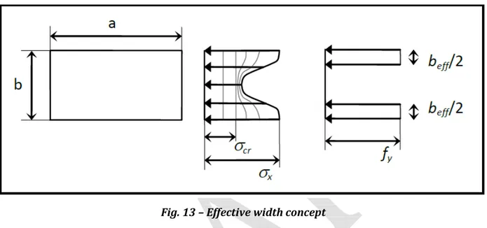
Fig. 13 – Effective width concept
The Eulerian critical buckling stress is derived using the assumption that the stress distribution stays linear. What actually happens in a buckled plate is that the stress redistribution away from the buckled part is a complex combined action of membrane stress induced by the load, bending stress due to the buckled shape and shear stress because of the rotation at the corners of the plate.
There have been developed methods for analysing a plate with this approach, for simple design purposes however these are too advanced to use. In 1932 Theodore von Kármán introduced the concept of effective width. He stated that (at a given thickness) a fictitious plate with the width of beff would have
the critical stress equal to the yield stress. If the actual plate has larger width, the capacity would be the same as that of the fictitious plate. Basically, with this approach, the real stress distribution is approximated, or replaced, with two strips which describe the load carrying effective width of the plate. With the above assumed stress distribution, the reduction factor can be derived by replacing the critical stress with the yield stress and the actual width with the effective width.
V*= MN@ & 12 1 − -& 7 ^^/. &= MN@ & 12 1 − -& 7/. &= 9L V*= 7 ^^/.1 &= 7/.1 &= 9L 7 ^^&V*= 7&9L
7 ^^ = 7[9VL * → U =
1 Y
Although von Kármán method gained reputation as a reliable way to determine the ultimate load of a plate, the method was still based on plates without initial imperfections. When compared to test results it was only valid for large b/t ratios, where initial imperfections have a smaller influence. However, von Kármán still is the first researcher to propose a reduction factor function and has had a large influence on all simplified design methods for plate buckling.
Winter approach
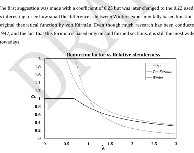
Since no manufactured plate is without initial deformation and residual stresses many researchers worked at adapting von Kármán formula. The function introduced by George Winter in 1947 is one of the more widely spreads in design codes. Winter conducted many experiments on cold formed steel sections and came up with:
U =77 = [^^ 9VL * _1 − 0.22[ 9L V*` = 1 Y :1 − 0.221Y ;
The first suggestion was made with a coefficient of 0.25 but was later changed to the 0.22 used now. It is interesting to see how small the difference is between Winters experimentally based function and the original theoretical function by von Kármán. Even though much research has been conducted since 1947, and the fact that this formula is based only on cold formed sections, it is still the most widely used nowadays.
Fig. 14 – Comparison between different approaches for local buckling of steel plates 0 0.2 0.4 0.6 0.8 1 1.2 1.4 1.6 1.8 2 0 0.5 1 1.5 2 2.5 3
ρ
λ
Reduction factor vs Relative slenderness
Euler Von Karman Winter
Eurocode 3 approach
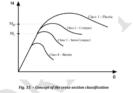
Eurocode 3 approach is not far from Winter’s proposal. Nevertheless, to account for the possibility of local buckling phenomena Eurocode 3 suggests a deemed-to-satisfy approach based on the classification of the cross-sections in four classes. The class is attributed based on the geometrical slenderness of the single plates composing the analysed member. The class accounts indirectly for the effect of local buckling on the resistance and rotational capacity of the cross-section. Eurocode 3 suggests four classes: i) plastic, ii) compact, iii) semi-compact and iv) slender, based on the possibility that the profiles are able or not to develop the yield or plastic resistance before that local buckling phenomena occur.
Fig. 15 – Concept of the cross-section classification
In particular, plastic and compact members (class-1 and class-2) are those characterized by a low slenderness of the isolated plates composing the cross-section and, therefore, they are able to develop the full plastic capacity (nevertheless, class-2 sections have a limited rotational capacity). Semi-compact cross-sections (class-3) are not able to achieve the full plastic capacity because local buckling phenomena occur after yielding initiation but before full plasticization of the cross-section. Finally, slender cross-sections (class-4) have a resistance limited by the occurrence of local buckling phenomena. They are occurring in elastic range, even before the achievement of the yielding capacity of the cross-section.
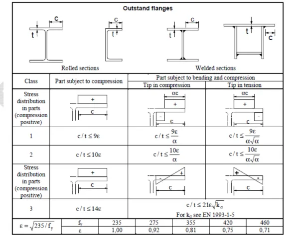
In common design practice, the cross-section classification is the first step to be performed when analysing a structural steel member. In order to avoid complicate calculations related to the assessment of the critical buckling stress of each of the plates composing the cross-section, which is not practical for everyday design, Eurocode 3 part 1.1 proposes simple rules to classify the individual plates of a
structural member, based on the stress distribution, which can be of pure compression, bending or combined compression and bending. Obviously, the parts of the cross-section which are subjected to tension can be directly classified as class-1. The class of the structural cross-section is defined according to the minimum class of the individual plates composing the cross-section. When the profile is class-1 or class-2 it can be designed or checked according to a plastic or elastic method. When the profile is class-3 it must be designed or checked according to an elastic method. Finally, when the profile is in class-4 reference has to be made to EC3 part 1.5 (and part 1.3 for cold-formed steel sections) accounting in the design for the occurrence of local buckling phenomena in elastic range. It is obvious that the cross-section classification strictly depends on the actions and boundary conditions, owing to the dependence of the buckling factor on the applied load and constraints (compression, bending or combined bending and compression, differentiating internal and outstand elements). Therefore, in general, a structural profile may be of a higher class in bending and lower in compression. Additionally, it is worth noting that, as far as the class of the cross-section is strictly related to the capacity of the profile to activate a sufficient rotational capacity, in seismic design the adoption of class-1 or class-2 cross sections is normally required.
Fig. 17 – Classification of internal plates
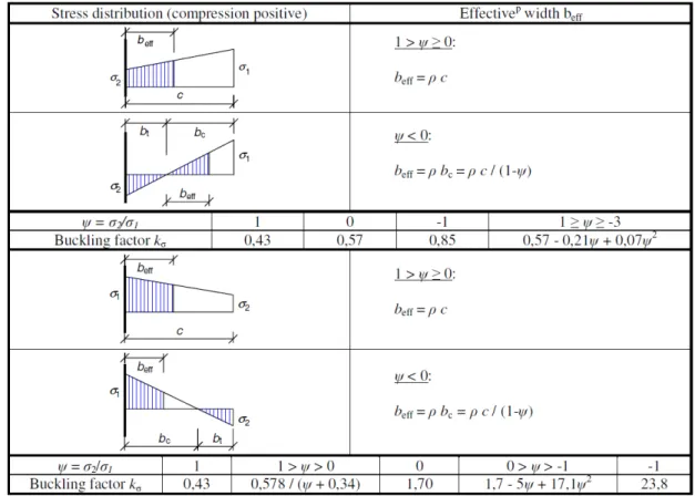
Eurocode 1.3 and 1.5 provide rules which are mainly based on the effective width method initially proposed by Von Karman and subsequently modified by Winter. According to the principles set by this method, from the practical point of view, the resistance of a class-4 cross-section is carried out reducing the plates widths according to their relative slenderness. The relative slenderness, as well as the loading and boundary conditions, as described before, are the main parameters influencing the load-carrying
capacity of a plate subjected to axial stresses. After defining the reduction coefficients for all the individual elements of the cross-section, the resistance is calculated according to an elastic methodology considering the contribution of the effective cross-section parts. The effective width method is ruled by Eurocode 3 part 1.5 in section 4.4, where the effective areas are defined accordingly with the indications given in the following tables. It is useful to observe that the imperfection factor is set by EC3 equal to 0.22 for the internal elements (as suggested by Winter), and equal to 0.188 for the outstand elements. The steps to define the effective section following EC3 part 1.5 provisions are: i) classify the cross-section according to tables 5.2 of EC3 part 1.1; ii) assuming that the cross-cross-section is slender (class-4), basing on an elastic distribution of stresses, calculate the buckling factor kσ according to tables 4.1 or 4.2 of EC3 part 1.5; iii) calculate the Eulerian critical buckling stress σcr,E of the individual plates in compression or combined bending and compression; iv) calculate the relative slenderness Y; v) calculate ρ, and thus the effective width beff=ρb, according to the Winter formula considering an
imperfection coefficient equal to 0.055(1+ψ) for internal plate elements and 0.188 for outstand plates;
vi) distribute the effective parts of the plate according to the rules set by EC3 part 1.5, described in tables 4.1 and 4.2; vii) with effective cross-section characteristics, design/check resistance and deflections.
Fig. 19 – Effective width calculation for internal compression elements
It is worth noting that the equations given in EC3 part 1.5 are a simplification of the theoretical equations for plate buckling previously defined.
Y = [ V* 9L= [ V*∙ 12 1 − -& 7& MN@& .& =7. [MNV* [12 1 − -& @& = 1.0527. [MNV*∙ 235∙ 235 =28.4 ∙ ∙ dMN7/. where = d235 V⁄ . The effective width can be calculated according to the following reduction factors: *
Internal compression elements:
U = 1 VfX Y ≤ 0.673
U = Yj5.5kk /lY] ≤ 1 VfX Y > 0.673, '>.ℎ 3 + > 0 Outstand compression elements:
U = 1 VfX Y ≤ 0.748
U = Yj5.\mmY] ≤ 1 VfX Y > 0.748
From these equations it is easy to verify that the reduction factor ρ, which is strictly related to Y , can be controlled limiting the 7/ . ratio within an adequate range. For flange elements of I-sections and box girders the stress ratio ψ used in Table 4.1 and Table 4.2 should be based on the properties of the gross cross-sectional area, due allowance being made for shear lag in the flanges if relevant. For web elements
the stress ratio ψ used in Table 4.1 should be obtained using a stress distribution based on the effective area of the compression flange and the gross area of the web.
1.2.2 Loads to be considered in the construction phase
The combination of actions has to be defined as usually done for any civil engineering construction according to the partial safety factor methodology ruled by Eurocode 1 and Eurocode 0. In practice, as aforesaid, there are two working conditions to be considered: construction (when the steel decking is used as a shuttering) and service (when the steel decking works as steel reinforcement of the composite floor).
The actions that can be applied simultaneously on the composite floor during the concreting phase may be in general: i) the dead load of the steel decking and of fresh concrete; ii) the construction loads including the working personnel with small site equipment; iii) the weight of additional formwork and of load-bearing members; iv) eventually the effect of ponding related to concrete accumulation (increased depth of concrete due to deflection of the sheeting).
The construction loads are ruled under Eurocode 1 part 1.6 at section 4.11.2. They must be considered as live loads. The recommended characteristic values of the actions due to construction loads during casting of concrete may vary depending on the structural scheme and span length. The characteristic value of the constructional live load must range from 0.75 kN/m2 to 1.5 kN/m2 applied to a working area
of 3 m x 3 m and must be considered equal to 0.75 kN/m2 in the remaining part of the span. The weight
of fresh concrete must be calculated consistently with the design thickness, according to Eurocode 1 part 1.1 provisions (in Table A.1). For normal fresh concrete weight must be assumed equal to 25 kN/m3.
The effect of ponding must be eventually considered in the check of the sheeting. EC4 states that if the central deflection δ of the sheeting under its own weight plus that of the wet concrete, calculated for serviceability, is less than 1/10 of the slab depth, the ponding effect may be ignored in the design of the steel sheeting. If this limit is exceeded, this effect should be allowed for. It may be assumed in design that the nominal thickness of the concrete is increased over the whole span by 0,7δ.
1.2.3 Design applications
Worked Example 1 – Check of a simply supported steel decking in the construction phase – EGB 210 In this example we check an EGB 210 steel decking in the construction phase. This typology of profiled sheeting (depth of 55 mm) is currently one of the most used for buildings. It is frequently adopted for spans of 2-3 m. It is made of S250GD steel, whose nominal yield strength is equal to 250 MPa.
Fig. 21 – Cross-section of the EGB 210 decking
We assume that the decking is designed according to a simply supported scheme, on a span of 2 m. The thickness of the steel sheeting is fixed to 0.8 mm, while the thickness of the concrete slab is supposed to extend 55 mm beyond the sheeting. Therefore, the composite floor has an overall depth of 110 mm (55 mm + 55 mm).
For the sake of simplicity, we refer to the single wave of the profiled steel sheeting. We first introduce the dead and live loads, then we calculate the gross geometrical properties of the decking (area, inertia and elastic modulus) and finally, by means of the effective width method, we calculate the effective cross-section properties. These properties are determined according to EC3 part 1.5 rules which, as aforesaid, are consistent with the Winter’s formulation. The checks to be carried out are in bending and shear at ULS, and for deflections under the SLS load combination. The single wave of the profiled steel sheeting can be characterized by means of the following geometrical parameters:
⎩ ⎪ ⎨ ⎪ ⎧7\. = 0.8 ??= 7&= 61 ?? ℎr= 55 ?? R ≅ 75° > = 150 ?? =r≅ 57 ??
The total height of the composite floor is 110 mm. In this example, we assume that there are not concentrated loads applied on the decking in the construction phase. The only live loads are those deriving from small construction tools and working personnel. Therefore, the following loads can be calculated for the construction phase:
Weight of fresh concrete: u ,^ v = 25 ∙I wxyz{
] ∙kkl\k5∙kkJ
\55| ∙\555\k5=2.063 kN/m Weight of profiled steel sheeting: u , = 0.1 kN/m
Weight of machinery: } ,~= 1.5 kN/m
Therefore, the design loads for the fundamental and characteristic combinations are:
ULS – Fundamental combination: } ,•€• = 1.35‚u ,^ v + u , ƒ + 1.5 ∙ } ,~ = 5.17 „
~
SLS – Characteristic combination: } ,•€• = u ,^ v + u , + } ,~= 3.66 „
~
For the reference structural scheme (simply supported beam), the bending and shear actions under the ULS load combination are:
Maximum bending moment: !~ ,•€•= } ,… †&⁄ = 5.17 ∙ 28 &⁄8 =2.59 MT? Maximum shear: ~ ,•€• = } ,… † 2⁄ = 5.06 ∙ 2 2 =⁄ 5.17 MT
"ˆ = .=7\71.=ℎ+ 72'+ .+ 2='=='ℎ' = 6161 + 61 + 2 ∙ 57∙ 55 + 57 ∙ 55 = 27.5 ?? <‰ = .= 71+ 72+ 2=' =0.8 ∙ 61 + 61 + 2 ∙ 57 = 188.8 ??& Š‰ = 71.= :ℎ'2; 2 +72.= :ℎ'2;2+ 2.=='123 sin2R + 2.=312=' cos2R=61 ∙ 0.8 27.5 2+ 61 ∙ 0.8 27.5 2 +20.8 ∙ 5712 0.933 + 2/ 0.812 ∙ 0.067 = 96484 /∙ 57 ??4 • ,‰ =2Šℎ'‰ = 2 ∙ 9648455 = 3508 ??/
Considering that, in this case, all the elements composing the cross-section are internal, according to Table 5.2 of Eurocode 3 part 1.1 they can be classified as follows:
Flange: 7\⁄ = 7. &⁄ = 61 0.8 ∙ 0.969. ⁄ = 73.88 - Class 4 Webs: =r⁄ = 57 0.8 ∙ 0.969. ⁄ = 73.53 – Class 2
Therefore, the cross-section is Class 4 and the effective width method must be applied to determine the effective cross-section properties. To this scope the relative slenderness of the plates must be first calculated. The flanges are subjected to uniform compression ( =1 , while the stress state of the web has to be determined based on the cross-sectional properties considering the effective area of the flanges and gross area of the web:
Flange: Y = 7&/. 28.4 ∙ ∙ dMN= 61/0.8 28.4 ∙ 0.969 ∙ √4= 1.385 ≥ 0.673 U = Y − 0.055 3 +Y& = Y − 0.22Y& = 0.607 7 ^^,\= U7\≅ 37 ??
The stress distribution on the web can be defined starting from the knowledge of the barycentre of the cross-section considering only the upper flange effective area:
"ˆ“” = 7 ^^,\.=ℎ'+ .=='ℎ'
.=‚7WVV,1+ 72+ 2='ƒ=
37 ∙ 55 + 57 ∙ 55
ψ= − "uV′ 2ℎ'−"uV′3
= − 55−24.424.4 = −0.797
Consequently, the effective web area can be calculated as follows:
Web: Y = =r/. 28.4 ∙ ∙ dMN= 57/0.8 28.4 ∙ 0.969 ∙ √19.03= 0.591 U = Y − 0.055 3 + Y& =0.688 − 0.055 3 − 0.7970.688& = 1.345 ≤ 1 → U = 1 = ^^,r= U=r= 57 ??
In conclusion, the effective cross-section has the following properties:
Fig. 23 – Geometrical parameters characterizing the effective cross-section
"ˆ–—“” =7 ^^,\.=ℎ'+ .=='ℎ' .= 71+ 72+ 2=' = 37 ∙ 55 + 57 ∙ 55 37 + 61 + 2 ∙ 57 ≅ 24.4 ?? →"ˆ˜™š” =ℎ'−"ˆ–—“” = 30.6 ?? < ^^ =.=‚7WVV1+ 72+ 2='ƒ =0.8 ∙ 37 + 61 + 2 ∙ 57 = 169.6 ??& Š ^^,ˆ” =7WVV1.= "ˆ˜™š” 2+72.= "ˆ –—“” 2+ 2.=='3 12 sin2R + 2.==' $ ℎ' 2 − "ˆ–—“” ) & =80684 ??F • , v^, ^^ =Š"^^,ˆ› ˆ–—“” = 80684 24.4 = 3306 ??/ • , …œ, ^^ =Š"^^,ˆ› ˆ˜™š” =8068430.6 = 2643 ??/
• , ^^= minž• , v^; • , …œ = 2643 ??/
The ratios between the gross and effective properties of the profiled sheeting are:
< ^^ <‰ = 169.6 188.8 = 0.898 Š ^^,ˆ” Š‰ = 80684 96484 = 0.836 • , ^^ • , ¡ =26433508 = 0.753
The downwards shift of the barycentre is equal to:
∆"ˆ = "ˆ− "ˆ–—“” = 3.1 mm
The check of the profiled sheeting in bending can be carried out calculating the elastic modulus referred to a 1 m width:
• , ^^,\~ = • , ^^1000> = 26431000150 = 17620 ??/ Therefore, the check in bending can be written as follows:
!£ = • , ^^,\~¤V*
¥5= 17620
250
1.0 ∙ 10¦ = 4.40 MT? ≥ !~ ,•€•= 2.53 MT?
The deformability of the steel decking must be checked referring to the effective properties of the cross-section and controlling that the deflection under the characteristic load combination is not exceeding 1/10 of the slab depth (110/10=11 mm) to avoid ponding or, eventually, L/180. As for the elastic modulus, also the inertia must be referred to a 1 m width:
Š ^^,ˆ”,\~ = Š ^^,ˆ”1000 > = 806841000150 = 537893 ??/ =3845 }Š,•€•†F ^^,ˆ” = 5 384 3.66 ∙ 2000 F 210000 ∙ 537893 = 6.75 ?? ≤ ~ ,•€• = 11 ??
The checks in bending and deflection must be accompanied by the check of the profiled sheeting in shear. This must be carried out considering the possibility of shear buckling at the support. In this case, reference has to be made to Eurocode 3 part 1.3 which suggests the following design equation:
r,£ =8rI ℎ r
sin R . V6§J
¤!0
Where 8r is the number of webs and fbv is the design shear stress. This formula is accounting for the
possible occurrence of local buckling phenomena by reducing the allowable shear stress. It must be determined starting from the knowledge of the web relative slenderness:
Yw = 0.346 ∙ =r/.[
V* = 0.346 ∙ 57/0.8[ 250
210000 = 0.846
The design stress is therefore defined according to the provisions given in Table 6.1 of EC3 part 1.3. In the current case, given the web slenderness, the design stress for shear checks has to be fixed equal to 0.48fyk/Yw=142MPa.
Therefore, the shear resistance of the sheeting is:
r,£ = 2 I 55sin R . V6§J ¤!0 1000150 = 2 I 550.966 0.8 ∙ 145J 1.0 ∙ 103 1000 142 = 88.13 MT ≥ ?A(,¨©ª= 5.06 MT
The check is therefore satisfied. It can be observed that, for the given design loads, support conditions and slab thickness, the maximum span that can be realized with this sheeting without intermediate props is:
ULS: bending moment check: †~ ,6 = d8!£ ⁄} ,… = d8 ∙ 4.40 5.06⁄ ≅ 2.64 ? ULS: shear check: †~ , = 2 r,£ ⁄} ,… = 88.13 ∙ 2 5.06 =⁄ 34.8 ?
SLS: deflection check: †~ , = [384 ~ ,•€• Š ^^,ˆ ” 5} ,•€• « = 10j/∙ [384 ∙ 11 ∙ 210000 ∙ 537893 5 ∙ 3.66 « ≅ 2.26 ?
Therefore, the most limiting check in this case is for deflection. Therefore, to use this decking on a span larger than 2.26 m, the use of props has to be suggested.
Worked Example 2 – Check of a simply supported steel decking in the construction phase with an intermediate temporary prop – EGB 210
In this example we check the same decking as before, considering a span of 3 m. The thickness of the steel sheeting is fixed to 1 mm, while the thickness of the concrete slab is supposed to extend 55 mm beyond the sheeting. Therefore, the composite floor has an overall depth of 110 mm (55 mm + 55 mm). Initially we make the hypothesis of simply supported bay an after verifying excessive deflection we decide to add a temporary prop for the construction phase.
As before reference is made to the single wave of the profiled sheeting. The construction loads are similar to the previous example. Only the dead load of the metal sheeting is slightly increased due to the increased thickness. The single wave of the profiled steel sheeting can be characterized by means of the following geometrical parameters:
⎩ ⎪ ⎨ ⎪ ⎧7\= 7. = 1 ??&= 61 ?? ℎr= 55 ?? R ≅ 75° > = 150 ?? =r≅ 57 ??
The total height of the composite floor is 110 mm. In this example, we assume that there are not concentrated loads applied on the decking in the construction phase. The only live loads are those deriving from small construction tools and working personnel. Therefore, the following loads can be calculated for the construction phase:
Weight of fresh concrete: u ,^ v = 25 ∙I wxyz{
] ∙kkl\k5∙kkJ
\55| ∙\555\k5=2.063 kN/m Weight of profiled steel sheeting: u , = 0.13 kN/m
Weight of machinery: } ,~= 1.5 kN/m
Therefore, the design loads for the fundamental and characteristic combinations are:
ULS – Fundamental combination: } ,•€• = 1.35‚u ,^ v + u , ƒ + 1.5 ∙ } ,~ = 5.21 „
~
SLS – Characteristic combination: } ,•€• = u ,^ v + u , + } ,~= 3.7 „
For the reference structural scheme (simply supported beam), the bending and shear actions under the ULS load combination are:
Maximum bending moment: !~ ,•€•= } ,… †&⁄ = 5.21 ∙ 38 &⁄8 =5.86 MT? Maximum shear: ~ ,•€• = } ,… † 2⁄ = 5.21 ∙ 3 2 =⁄ 7.82 MT
The gross properties of the metal decking can be calculated as follows:
"ˆ = .7\.=ℎ'+ .=='ℎ' = 71+ 72+ 2=' = 61∙ 55 + 57 ∙ 55 61 + 61 + 2 ∙ 57 = 27.5 ?? <‰ = .= 71+ 72+ 2=' =1 ∙ 61 + 61 + 2 ∙ 57 = 236 ??& Š‰ = 71.= :ℎ2'; 2 +72.= :ℎ2';2+ 2.12=='3 sin2R + 2.=3=' 12 cos2R=61 ∙ 1 27.5 2+ 61 ∙ 1 27.5 2 +21 ∙ 5712 0.933 + 2/ 1/12 ∙ 0.067 = 121069 ∙ 57 ??4 • ,‰ =2Šℎ‰ ' = 2 ∙ 121069 55 = 4402 ??/
The elements composing the cross-section are internal and, according to Table 5.2 of Eurocode 3 part 1.1, they can be classified as follows:
Flange: 7\⁄ = 7. &⁄ = 61 1 ∙ 0.969. ⁄ = 62.95 - Class 4 Webs: =r⁄ = 57 1 ∙ 0.969. ⁄ = 58.8 – Class 1
Therefore, the cross-section is Class 4 and the effective width method must be applied to determine the effective cross-section properties. To this scope the relative slenderness of the plates must be first calculated. The flanges are subjected to uniform compression ( =1 , while the stress state of the web has to be determined based on the cross-sectional properties considering the effective area of the flanges and gross area of the web:
Flange: Y = 7&/. 28.4 ∙ ∙ dMN= 61/1 28.4 ∙ 0.969 ∙ √4= 1.108 ≥ 0.673 U = Y − 0.055 3 +Y& = Y − 0.22Y& = 0.723 7 ^^,\= U7\≅ 44 ??
The stress distribution on the web can be defined starting from the knowledge of the barycentre of the cross-section considering only the upper flange effective area:
"ˆ“” =7 ^^,\.=ℎ'+ .=='ℎ' .= 71+ 72+ 2=' = 44 ∙ 55 + 57 ∙ 55 44 + 61 + 2 ∙ 57 ≅ 25.4 ?? ψ= − "uV′ 2ℎ'−"uV′3 = − 55−25.425.4 = −0.858
Consequently, the effective web area can be calculated as follows:
Web: Y = =r/. 28.4 ∙ ∙ dMN= 57/1 28.4 ∙ 0.969 ∙ √20.9= 0.453 U = Y − 0.055 3 +Y& =0.453 − 0.055 3 − 0.8580.453& = 1.63 ≤ 1 → U = 1 = ^^,r= U=r= 57 ??
In conclusion, the effective cross-section has the following properties:
"ˆ–—“” =7 ^^,\.=ℎ'+ .=='ℎ' .= 71+ 72+ 2=' = 44 ∙ 55 + 57 ∙ 55 44 + 61 + 2 ∙ 57 = 25.4 ?? →"ˆ˜™š” =ℎ'−"ˆ–—“” = 29.6 ?? < ^^ =.=‚7WVV1+ 72+ 2='ƒ =1 ∙ 44 + 61 + 2 ∙ 57 = 219 ??& Š ^^,ˆ” =7WVV1.= "ˆ˜™š” 2+72.= "ˆ –—“” 2+ 2 .=='3 12 sin2R + 2.==' $ ℎ' 2 − "ˆ–—“” ) & =107206 ??F • , v^, ^^ =Š"^^,ˆ› ˆ–—“” = 107206 25.4 = 4220 ??/ • , …œ, ^^ =Š"^^,ˆ› ˆ˜™š” =10720629.6 = 3622 ??/ • , ^^= minž• , v^; • , …œ = 3622 ??/
The ratios between the gross and effective properties of the profiled sheeting are:
< ^^
<‰ =
219
Š ^^,ˆ” Š‰ = 107206 121069 = 0.885 • , ^^ • , ¡ =36224402 = 0.823
The downwards shift of the barycentre is equal to:
∆"ˆ = "ˆ− "ˆ–—“” = 2.1 mm
The check of the profiled sheeting in bending can be carried out calculating the elastic modulus referred to a 1 m width:
• , ^^,\~ = • , ^^1000> = 36221000150 = 24146 ??/ Therefore, the check in bending can be written as follows:
!£ = • , ^^,\~¤V*
¥5= 24146
250
1.0 ∙ 10¦ = 6.04 MT? ≥ !~ ,•€•= 5.86 MT?
The deformability of the steel decking must be checked referring to the effective properties of the cross-section and controlling that the deflection under the characteristic load combination is not exceeding 1/10 of the slab depth (110/10=11 mm) to avoid ponding or, eventually, L/180. As for the elastic modulus, also the inertia must be referred to a 1 m width:
Š ^^,ˆ”,\~ = Š ^^,ˆ”1000 > = 1072061000150 = 714707 ??/ =3845 }Š,•€•†F ^^,ˆ” = 5 384 3.7 ∙ 3000 F 210000 ∙ 714707 = 26 ?? > ~ ,•€•= 11 ??
The checks must be accompanied by the check of the profiled sheeting in shear. The previous equations are applied:
Yw = 0.346 ∙ =r/.[V* = 0.346 ∙ 57/1[ 250
210000 = 0.677
The design stress is therefore defined according to the provisions given in Table 6.1 of EC3 part 1.3. In the current case, given the web slenderness, the design stress for shear checks has to be fixed equal to 0.58fyk=145MPa (It is equivalent to fyk/√3). Therefore, the shear resistance of the sheeting is:
r,£ =2 I 55sin R . V¤ 6§J !0 1000 150 = 2 I 550.966 1 ∙ 145J 1.0 ∙ 103 1000 150 = 110.16 MT ≥ ?A(,¨©ª= 7.82 MT
The check is therefore satisfied. The deformability is excessive. This issue can be solved with a pre-camber or adding an intermediate prop. In this case the second solution is preferred. The structural scheme becomes a beam on three supports. The maximum deflection in this scheme is obtained by maximizing the load on one of the two spans and minimizing the load on the other. Therefore, we consider the presence of fresh concrete only on one span, while the other span is unloaded. With this scheme, the maximum deflection becomes:
≅1101 } ,•€•I†2J F Š ^^,ˆ” = 1 110 3.7 ∙ 1500 F 210000 ∙ 717070 = 1.13 ?? ≤ ~ ,•€•= 11 ??
With the intermediate prop the check becomes fully satisfied.
Worked Example 3 – Check of a steel decking in the construction phase on a double span – EGB 210 In this example we check always the same typology of decking. We consider that the composite floor is supported with continuity on a scheme with two bays. We consider this time a sheeting of 1.2 mm thickness. The two bays have a span of 3. m. The properties are determined according to EC3 part 1.5 rules as usual. The single wave of the profiled steel sheeting can be characterized by means of the following geometrical parameters:
⎩ ⎪ ⎨ ⎪ ⎧7\. = 1.2 ??= 7&= 61 ?? ℎr= 55 ?? R ≅ 75° > = 150 ?? =r≅ 57 ??
The total height of the composite floor is 110 mm. In this example, we assume that there are not concentrated loads applied on the decking in the construction phase. The only live loads are those deriving from small construction tools and working personnel. Therefore, the following loads can be calculated for the construction phase:
Weight of fresh concrete: u ,^ v = 25 ∙I wxyz{
] ∙kkl\k5∙kkJ
\55| ∙\555\k5=2.063 kN/m Weight of profiled steel sheeting: u , = 0.16 kN/m
Weight of machinery: } ,~= 1.5 kN/m
Therefore, the design loads for the fundamental and characteristic combinations are:
ULS – Fundamental combination: } ,•€• = 1.35‚u ,^ v + u , ƒ + 1.5 ∙ } ,~ = 5.25 „
~
SLS – Characteristic combination: } ,•€• = u ,^ v + u , + } ,~= 3.72 „
~
The bending moments in a two-spans scheme can be maximized according to two different load combinations. One maximizing the negative bending moment at the intermediate support, the other maximizing the sagging bending moment in the spans. The first load combination provides to spread the magnified characteristic loads on both spans, the second combination provides to apply the load only on one span, while on the other no loads are applied. The peak values of the actions in these two design schemes are:
1 – Loads applied uniformly on both span with the magnified value
Maximum hogging bending moment: !\~ j,•€• = } ,… †&⁄ = 5.25 ∙ 3.38 &⁄8 =7.15 MT?
Maximum sagging bending moment: !\~ l,•€• = } ,… †&⁄ = 5.25 ∙ 3.316 &⁄16 =3.57 MT?
Maximum shear: ~ ,•€•= 0.625} ,… † = 0.625 5.25 ∙ 3.3 = 10.83 MT
2 – Loads applied only on the left or right span with the magnified value
Maximum hogging bending moment: !\~ j,•€• = } ,… †&⁄ = 5.25 ∙ 3.316 &⁄16 =3.57 MT?
Maximum sagging bending moment: !\~ l,•€• = ‚49} ,… †&ƒ 512⁄ ≅ } ,… †&⁄ =10
5.25 ∙ 3.3&⁄10 =5.72 MT?
Maximum shear: ~ ,•€• = ¬-®,™¯˜
\¦ =
¬∙k.&k∙/./
\¦ = 9.75 MT
The gross properties of the metal decking can be calculated as follows:
"ˆ = .7\.=ℎ'+ .=='ℎ' = 71+ 72+ 2=' = 61∙ 55 + 57 ∙ 55 61 + 61 + 2 ∙ 57 = 27.5 ?? <‰ = .= 71+ 72+ 2=' =1.2 ∙ 61 + 61 + 2 ∙ 57 = 283.2 ??& Š‰ = 71.= :ℎ2'; 2 +72.= :ℎ2';2+ 2.12=='3 sin2R + 2.=3=' 12 cos2R=61 ∙ 1.2 27.5 2+ 61 ∙ 1.2 27.5 2
+21.2 ∙ 5712 0.933 + 2/ 1.212 ∙ 0.067 = 145273 /∙ 57 ??4
• ,‰ =2Šℎ‰ ' =
2 ∙ 145273
55 = 5283 ??/
Considering that, in this case, all the elements composing the cross-section are internal, according to Table 5.2 of Eurocode 3 part 1.1 they can be classified as follows:
Flange: 7\⁄ = 7. &⁄ = 61 1.2 ∙ 0.969. ⁄ = 52.45 - Class 4 Webs: =r⁄ = 57 1.2 ∙ 0.969. ⁄ = 49 – Class 1
Therefore, the cross-section is Class 4 and the effective width method must be applied to determine the effective cross-section properties. To this scope the relative slenderness of the plates must be first calculated. The flanges are subjected to uniform compression ( =1 , while the stress state of the web has to be determined based on the cross-sectional properties considering the effective area of the flanges and gross area of the web:
Flange: Y = 7&/. 28.4 ∙ ∙ dMN= 61/1.2 28.4 ∙ 0.969 ∙ √4= 0.923 ≥ 0.673 U = Y − 0.055 3 +Y& = Y − 0.22Y& = 0.825 7 ^^,\= U7\≅ 50.4 ??
The stress distribution on the web can be defined starting from the knowledge of the barycentre of the cross-section considering only the upper flange effective area:
"ˆ“” =7 ^^,\.=ℎ'+ .=='ℎ' .= 71+ 72+ 2=' = 50.4 ∙ 55 + 57 ∙ 55 50.4 + 61 + 2 ∙ 57 ≅ 26.2 ?? ψ= − "uV′ 2ℎ'−"uV′3 = − 55−26.226.2 = −0.909
Consequently, the effective web area can be calculated as follows:
Web:
Y = =r/. 28.4 ∙ ∙ dMN=
57/1.2
U = Y − 0.055 3 +
Y& =0.371 − 0.055 3 − 0.9090.371& = 1.86 ≤ 1 → U = 1 = ^^,r= U=r= 57 ??
In conclusion, the effective cross-section has the following properties:
"ˆ–—“” =7 ^^,\.=ℎ'+ .=='ℎ' .= 71+ 72+ 2=' = 50.4 ∙ 55 + 57 ∙ 55 50.4 + 61 + 2 ∙ 57 ≅ 26.2 ?? →"ˆ˜™š” = ℎ'−"ˆ–—“” = 28.8 ?? < ^^ =.=‚7WVV1+ 72+ 2='ƒ =1.2 ∙ 50.4 + 61 + 2 ∙ 57 = 270.5 ??& Š ^^,ˆ” =7WVV1.= "ˆ˜™š” 2+72.= "ˆ –—“” 2+ 2.=='3 12 sin2R + 2.==' $ ℎ' 2 − "ˆ–—“” ) & =135498 ??F • , v^, ^^ =Š"^^,ˆ› ˆ–—“” =13549826.2 = 5171 ??/ • , …œ, ^^ =Š"^^,ˆ› ˆ˜™š” =13549828.8 = 4705 ??/ • , ^^= minž• , v^; • , …œ = 4705 ??/
The ratios between the gross and effective properties of the profiled sheeting are:
< ^^ <‰ = 270.5 283.2 = 0.955 Š ^^,ˆ” Š‰ = 135498 145273 = 0.932 • , ^^ • , ¡ =47055283 = 0.891
The downwards shift of the barycentre is equal to:
∆"ˆ = "ˆ− "ˆ–—“” =1.3 mm
The check of the profiled sheeting in bending can be carried out calculating the elastic modulus referred to a 1 m width:
Due to symmetry of the cross-section the elastic modulus for positive bending is equal to the elastic modulus for negative bending. Therefore, the check in bending can be written directly as follows:
!£ = • , ^^,\~¤V*
¥5= 31366
250
1.0 ∙ 10¦ = 7.84 MT? ≥ °!~ ,•€•° = 7.15 MT?
The deformability of the steel decking must be checked referring to the effective properties of the cross-section and controlling that the deflection under the characteristic load combination is not exceeding 1/10 of the slab depth (110/10=11 mm) to avoid ponding or, eventually, L/180. The scheme with fresh concrete only on one span and the other span unloaded is the most severe. With this scheme, the maximum deflection becomes:
Š ^^,ˆ”,\~ = Š ^^,ˆ”1000 > = 1354981000150 = 903320 ??/ =1101 } ,•€•Š † F ^^,ˆ” = 1 110 3.72 ∙ 3300 F 210000 ∙ 903320 = 21.14 ?? ≤ ~ ,•€• = 11 ??
As in the previous case the use of props is required. As shown before the addition of one prop at the center of the span may be suggested.
The checks must be accompanied by the check of the profiled sheeting in shear. The previous equations are applied:
Yw = 0.346 ∙ =r/.[V* = 0.346 ∙ 57/1.2[ 250
210000 = 0.8124
The design stress is therefore defined according to the provisions given in Table 6.1 of EC3 part 1.3. In the current case, given the web slenderness, the design stress for shear checks has to be fixed equal to 0.58fyk=145MPa (It is equivalent to fyk/√3). Therefore, the shear resistance of the sheeting is:
r,£ = 2 I 55sin R . V6§J ¤!0 1000150 = 2 I 550.966 1.2 ∙ 145J 1.0 ∙ 103 1000 150 = 132.19 MT ≥ ?A(,¨©ª= 10.82 MT
Worked Example 4 – Check of a simply supported steel decking in the construction phase – EGB 1200
In this example we check an EGB 1200 steel decking in the construction phase. This typology of profiled sheeting (depth of 75 mm) is also one of the most frequently used in construction practice. It can cover spans slightly larger than the previous sheeting. The shape allows to lighten slightly the composite floor for a given depth. It is made of S250GD steel, whose nominal yield strength is equal to 250 MPa. In this
example, for the sake of simplicity, we neglect the effect of the ribs in the upper flange of the decking. In reality, the stiffeners increase the out-of-plane inertia of the upper plates reducing slightly the issues related to the occurrence of possible local buckling phenomena.
Fig. 24 – Cross-section of the EGB 1200 decking
We assume that the decking is designed according to a simply supported scheme, on a span of 2.5 m. The thickness of the steel sheeting is fixed to 0.8 mm, while the thickness of the concrete slab is supposed to extend 45 mm beyond the sheeting. Therefore, the composite floor has an overall depth of 120 mm (75 mm + 45 mm).
We proceed as previously done, first introducing the geometrical properties of the sheeting and the loads and then we perform the structural checks in bending and shear at ULS, and for deflections under the SLS load combination. The single wave of the profiled steel sheeting can be characterized by means of the following geometrical parameters:
⎩ ⎪⎪ ⎨ ⎪⎪ ⎧7\7&= 126 ??= 40 ?? . = 0.8 ?? ℎr= 75 ?? R ≅ 81° > = 190 ?? =r≅ 76 ??
The total height of the composite floor is 120 mm. In this example, we assume that there are not concentrated loads applied on the decking in the construction phase. The only live loads are those deriving from small construction tools and working personnel. Therefore, the following loads can be calculated for the construction phase:
Weight of fresh concrete: u ,^ v = 25 ∙I z«y«±
] ∙²kl\¬5∙FkJ
\55| ∙\555\¬5=1.64 kN/m Weight of profiled steel sheeting: u , = 0.11 kN/m
Therefore, the design loads for the fundamental and characteristic combinations are:
ULS – Fundamental combination: } ,•€• = 1.35‚u ,^ v + u , ƒ + 1.5 ∙ } ,~ = 4.61 „
~
SLS – Characteristic combination: } ,•€• = u ,^ v + u , + } ,~= 3.25 „
~
For the reference structural scheme (simply supported beam), the bending and shear actions under the ULS load combination are:
Maximum bending moment: !~ ,•€•= } ,… †&⁄ = 4.61 ∙ 2.58 &⁄8 =3.6 MT? Maximum shear: ~ ,•€• = } ,… † 2⁄ = 4.61 ∙ 2.5 2 =⁄ 5.76 MT
The gross properties of the metal decking can be calculated as follows:
"ˆ = .7\.=ℎ'+ .=='ℎ' = 71+ 72+ 2=' = 126∙ 75 + 76 ∙ 75 126 + 40 + 2 ∙ 76 = 47.64 ?? <‰ = .= 71+ 72+ 2=' =0.8 ∙ 126 + 40 + 2 ∙ 76 = 254.4 ??& Š‰ ≅71.= ℎ'−"ˆ 2+72.= "ˆ 2+ 2.==' 3 12 sin2R+ 2.==' : ℎ' 2 − "ˆ; & = 126 ∙ 0.8 27.36 2+ 40 ∙ 0.8 47.64 2+ 20.8 ∙ 763 12 0.976 +2 ∙0.8 ∙ 76 −10.14 & = 217543 ??F • ,‰, v^ ="Š‰ ˆ = 217543 47.64 = 4566 ??/ • ,‰, …œ = ℎ Š‰ '−"ˆ = 217543 27.36 = 7951 ??/ • ,‰ = min • ,‰, v^; • ,‰, …œ = 4566 ??/
Considering that, in this case, all the elements composing the cross-section are internal, according to Table 5.2 of Eurocode 3 part 1.1 they can be classified as follows:
Flange: 7\⁄ = 126 0.8 ∙ 0.969. ⁄ = 162.5 - Class 4 Webs: =r⁄ = 76 0.8 ∙ 0.969. ⁄ = 98.03 – Class 3
Therefore, the cross-section is Class 4 and the effective width method must be applied to determine the effective cross-section properties. To this scope the relative slenderness of the plates must be first
calculated. The upper flange is subjected to uniform compression ( =1 , while the stress state of the web has to be determined based on the cross-sectional properties considering the effective area of the flanges and gross area of the web:
Flange: Y = 7&/. 28.4 ∙ ∙ dMN= 126/0.8 28.4 ∙ 0.969 ∙ √4= 2.86 ≥ 0.673 U = Y − 0.055 3 +Y& = Y − 0.22Y& = 0.323 7 ^^,\= U7\≅ 40.7 ??
The stress distribution on the web can be defined starting from the knowledge of the barycentre of the cross-section considering the upper flange effective area:
"ˆ“” =7 ^^,\.=ℎ'+ .=='ℎ' .= 71+ 72+ 2=' = 40.7 ∙ 75 + 76 ∙ 75 40.7 + 40 + 2 ∙ 76 ≅ 37.6 ?? ψ= − "uV′ 2ℎ'−"uV′3 = − 75−37.637.6 = −1
Consequently, the effective web area can be calculated as follows:
Web: Y = =r/. 28.4 ∙ ∙ dMN= 76/0.8 28.4 ∙ 0.969 ∙ √23.9= 0.706 U = Y − 0.055 3 + Y& =0.706 − 0.055 3 − 10.706& = 1.2 ≤ 1 → U = 1 = ^^,r= U=r= 76 ??
In conclusion, the effective cross-section has the following properties:
"ˆ–—“” =7 ^^,\.=ℎ'+ .=='ℎ' .= 71+ 72+ 2=' = 40.7 ∙ 75 + 76 ∙ 75 40.7 + 40 + 2 ∙ 76 ≅ 37.6 ?? →"ˆ˜™š” = ℎ'−"ˆ–—“” = 37.4 ?? < ^^ =.=‚7WVV1+ 72+ 2='ƒ =0.8 ∙ 40.7 + 40 + 2 ∙ 76 = 186.16 ??& Š ^^,ˆ” =7WVV1.= "ˆ˜™š” 2+72.= "ˆ –—“” 2+ 2.=='3 12 sin2R + 2.==' $ ℎ' 2 − "ˆ–—“” ) & =147883 ??F
• , v^, ^^ =Š"^^,ˆ› ˆ–—“” = 147883 37.6 = 3933 ??/ • , …œ, ^^ =Š"^^,ˆ› ˆ˜™š” =14788337.4 = 3954 ??/ • , ^^= minž• , v^; • , …œ = 3933 ??/
The ratios between the gross and effective properties of the profiled sheeting are:
< ^^ <‰ = 186.16 254.4 = 0.732 Š ^^,ˆ” Š‰ = 147883 217543 = 0.679 • , ^^ • , ¡ =39334566 = 0.861
The downwards shift of the barycentre is equal to:
∆"ˆ = "ˆ− "ˆ–—“” = 10 mm
The check of the profiled sheeting in bending can be carried out calculating the elastic modulus referred to a 1 m width:
• , ^^,\~ = • , ^^1000> = 39541000190 = 20810 ??/ Therefore, the check in bending can be written as follows:
!£ = • , ^^,\~¤V*
¥5= 2081
250
1.0 ∙ 10¦ = 5.2 MT? ≥ !~ ,•€•= 3.6 MT?
The deformability of the steel decking must be checked referring to the effective properties of the cross-section and controlling that the deflection under the characteristic load combination is not exceeding 1/10 of the slab depth (110/10=11 mm) to avoid ponding or, eventually, L/180. As for the elastic modulus, also the inertia must be referred to a 1 m width:
Š ^^,ˆ”,\~ = Š ^^,ˆ”1000 > = 1478831000190 = 778332 ??/ =3845 }Š,•€•†F ^^,ˆ” = 5 384 3.25 ∙ 2500 F 210000 ∙ 778332 = 10.1?? ≤ ~ ,•€• = 11 ??
The checks in bending and deflection must be accompanied by the check of the profiled sheeting in shear. This must be carried out considering the possibility of shear buckling at the support. In this case, reference has to be made to Eurocode 3 part 1.3 which suggests the following design equation:
r,£ =8rI ℎ r
sin R . V6§J
¤!0
Where 8r is the number of webs and fbv is the design shear stress. This formula is accounting for the
possible occurrence of local buckling phenomena by reducing the allowable shear stress. It must be determined starting from the knowledge of the web relative slenderness:
Yw = 0.346 ∙ =r/.[
V* = 0.346 ∙ 76/0.8[ 250
210000 = 1.134
The design stress is therefore defined according to the provisions given in Table 6.1 of EC3 part 1.3. In the current case, given the web slenderness, the design stress for shear checks has to be fixed equal to 0.48fyk/Yw=106MPa.
Therefore, the shear resistance of the sheeting is:
r,£ =2 I 55sin R . V¤ 6§J !0 1000 190 = 2 I 760.987 0.8 ∙ 106J 1.0 ∙ 103 1000 190 = 68.73 MT ≥ ?A(,¨©ª= 5.76 MT
The check is therefore satisfied. It can be observed that, for the given design loads, support conditions and slab thickness, the maximum span that can be realized with this sheeting without intermediate props is:
ULS: bending moment check: †~ ,6 = d8!£ ⁄} ,… = d8 ∙ 5.2 4.61⁄ ≅ 3 ? ULS: shear check: †~ , = 2 r,£ ⁄} ,… = 68.73 ∙ 2 4.61 =⁄ 29.8 ?
†~ , = [384 ~ ,•€• Š ^^,ˆ ” 5} ,•€• « = 10j/∙ [384 ∙ 11 ∙ 210000 ∙778332 5 ∙ 3.25 « ≅ 2.55 ?
Therefore, the most limiting check in this case is for deflection. Therefore, to use this decking on a span larger than 2.55 m, the use of props has to be suggested.
Worked Example 5 – Check of a simply supported steel decking in the construction phase – SAND 100
In this example we check a SAND 100 steel decking in the construction phase. This typology of profiled sheeting (depth of 100 mm) is conceived for applications on large spans. It is often used also for roofs. It is made of S250GD steel, whose nominal yield strength is equal to 250 MPa.
Fig. 25 – Cross-section of the SAND 100 decking
We assume that the decking is designed according to a simply supported scheme, on a span of 3.5 m. The thickness of the steel sheeting is fixed to 1.2 mm with a tolerance of execution to be considered according to the producer equal to the 15%. The design thickness of the concrete slab is supposed to extend 45 mm beyond the sheeting. Therefore, the composite floor has an overall depth of 145 mm (100 mm + 45 mm).
We proceed as previously done, first introducing the geometrical properties of the sheeting and the loads and then we perform the structural checks in bending and shear at ULS, and for deflections under the SLS load combination. The single wave of the profiled steel sheeting can be characterized by means of the following geometrical parameters:
⎩ ⎪⎪ ⎨ ⎪⎪ ⎧ 7\7&= 70 ??= 40 ?? . = 1.07 ?? ℎr = 100 ?? R ≅ 74° > = 166 ?? =r ≅ 104 ??
The total height of the composite floor is 145 mm. In this example, we assume that there are not concentrated loads applied on the decking in the construction phase. The only live loads are those deriving from small construction tools and working personnel. Therefore, the following loads can be calculated for the construction phase:
Weight of fresh concrete: u ,^ v = 25 ∙I xzy«±
] ∙\55l\¦¦∙FkJ
\55| ∙\555\¦¦=2.15 kN/m Weight of profiled steel sheeting: u , = 0.16 kN/m
Weight of machinery: } ,~= 1.5 kN/m
Therefore, the design loads for the fundamental and characteristic combinations are:
ULS – Fundamental combination: } ,•€• = 1.35‚u ,^ v + u , ƒ + 1.5 ∙ } ,~ = 5.37 „
~
SLS – Characteristic combination: } ,•€• = u ,^ v + u , + } ,~= 3.81 „
~
For the reference structural scheme (simply supported beam), the bending and shear actions under the ULS load combination are:
Maximum bending moment: !~ ,•€•= } ,… †&⁄ = 5.37 ∙ 3.58 &⁄8 =8.22 MT? Maximum shear: ~ ,•€• = } ,… † 2⁄ = 5.37 ∙ 3.5 2 =⁄ 9.39 MT
The gross properties of the metal decking can be calculated as follows:
"ˆ = .7\.=ℎ'+ .=='ℎ' = 71+ 72+ 2=' =
70∙ 100 + 40 ∙ 100
70 + 40 + 2 ∙ 104 = 54.72 ??
Š‰ ≅71.= ℎ'−"ˆ 2+72.= "ˆ 2+ 2.==' 3 12 sin2R+ 2.==' : ℎ' 2 − "ˆ; & = 70 ∙ 1.07 45.28 2+ 40 ∙ 1.07 54.72 2+ 21.07 ∙ 1043 12 0.927 +2 ∙1.07 ∙ 104 −4.72 & = 471864 ??F • ,‰, v^ ="Š‰ ˆ = 471864 54.72 = 8623 ??/ • ,‰, …œ = ℎ Š‰ '−"ˆ = 471864 45.28 = 10421 ??/ • ,‰ = min • ,‰, v^; • ,‰, …œ = 8623 ??/
Considering that, in this case, all the elements composing the cross-section are internal, according to Table 5.2 of Eurocode 3 part 1.1 they can be classified as follows:
Flange: 7\⁄ = 70 1.07 ∙ 0.969. ⁄ = 72.23 - Class 4 Webs: =r⁄ = 104 1.07 ∙ 0.969. ⁄ = 100.3 – Class 3
Therefore, the cross-section is Class 4 and the effective width method must be applied to determine the effective cross-section properties. To this scope the relative slenderness of the plates must be first calculated. The upper flange is subjected to uniform compression ( =1 , while the stress state of the web has to be determined based on the cross-sectional properties considering the effective area of the flanges and gross area of the web:
Flange: Y = 7&/. 28.4 ∙ ∙ dMN= 70/1.07 28.4 ∙ 0.969 ∙ √4= 1.188 ≥ 0.673 U = Y − 0.055 3 +Y& = Y − 0.22Y& = 0.686 7 ^^,\= U7\≅ 48 ??
The stress distribution on the web can be defined starting from the knowledge of the barycentre of the cross-section considering the upper flange effective area:
"ˆ“” =7 ^^,\.=ℎ'+ .=='ℎ'
.= 71+ 72+ 2=' =
48 ∙ 100 + 104 ∙ 100
ψ= − "uV′ 2ℎ'−"uV′3
= − 75−51.3551.35 = −1.06
Consequently, the effective web area can be calculated as follows:
Web: Y = =r/. 28.4 ∙ ∙ dMN= 104/1.07 28.4 ∙ 0.969 ∙ √25.3= 0.701 U = Y − 0.055 3 + Y& =0.701 − 0.055 3 − 1.060.701& = 1.21 ≤ 1 → U = 1 = ^^,r= U=r= 104 ??
In conclusion, the effective cross-section has the following properties:
"ˆ–—“” =7 ^^,\.=ℎ'+ .=='ℎ' .= 71+ 72+ 2=' = 48 ∙ 100 + 104 ∙ 100 48 + 40 + 2 ∙ 104 ≅ 51.35 ?? →"ˆ˜™š” = ℎ'−"ˆ–—“” = 48. ?? < ^^ =.=‚7WVV1+ 72+ 2='ƒ =1.07 ∙ 48 + 40 + 2 ∙ 104 = 316.4 ??& Š ^^,ˆ” =7WVV1.= "ˆ˜™š” 2+72.= "ˆ –—“” 2+ 2.=='3 12 sin2R + 2.==' $ ℎ' 2 − "ˆ–—“” ) & =420044 ??F • , v^, ^^ =Š"^^,ˆ› ˆ–—“” = 420044 51.35 = 8179 ??/ • , …œ, ^^ =Š"^^,ˆ› ˆ˜™š” =42004448.65 = 8635 ??/ • , ^^= minž• , v^; • , …œ = 8179 ??/
The ratios between the gross and effective properties of the profiled sheeting are:
< ^^ <‰ = 316.4 339.9 = 0.93 Š ^^,ˆ” Š‰ = 420044 471864 = 0.89 • , ^^ • , ¡ =81798623 = 0.95
The downwards shift of the barycentre is equal to:
∆"ˆ = "ˆ− "ˆ–—“” = 6.08 mm
The check of the profiled sheeting in bending can be carried out calculating the elastic modulus referred to a 1 m width:
• , ^^,\~ = • , ^^1000> = 81791000166 = 49273 ??/ Therefore, the check in bending can be written as follows:
!£ = • , ^^,\~¤V*
¥5= 49273
250
1.0 ∙ 10¦ = 12.3 MT? ≥ !~ ,•€•= 8.22 MT?
The deformability of the steel decking must be checked referring to the effective properties of the cross-section and controlling that the deflection under the characteristic load combination is not exceeding 1/10 of the slab depth (145/10=14.5 mm) to avoid ponding or, eventually, L/180. As for the elastic modulus, also the inertia must be referred to a 1 m width:
Š ^^,ˆ”,\~ = Š ^^,ˆ”1000 > = 4200441000166 = 2530386 ??/ =3845 }Š,•€•†F ^^,ˆ” = 5 384 3.81 ∙ 3500 F 210000 ∙ 2530386 = 14.01?? ≤ ~ ,•€• = 14.5 ??
The checks in bending and deflection must be accompanied by the check of the profiled sheeting in shear. This must be carried out considering the possibility of shear buckling at the support. In this case, reference has to be made to Eurocode 3 part 1.3 which suggests the following design equation:
r,£ =8rI ℎ r
sin R . V6§J
¤!0
Where 8r is the number of webs and fbv is the design shear stress. This formula is accounting for the
possible occurrence of local buckling phenomena by reducing the allowable shear stress. It must be determined starting from the knowledge of the web relative slenderness:
Yw = 0.346 ∙ =r/.[V* = 0.346 ∙ 104/1.07[ 250