2 TOOL CONDITION
MONITORING: DEFINITION AND
STATE-OF-THE-ART
The capability of monitoring machining processes has a strong economic potential today, by the large benefits in exploiting tools up to their real end-of-life; this can be reached once the decay mechanisms are clearly defined and understood. Operative choices in tool management usually rely on conservative evaluations of tool-life, because of the empirical knowledge about failure mechanisms; this fact leads to an unnecessarily high number of changes and to increase of cost impacts. Particularly in automated production systems, where an intensive endeavour is made with respect to machining settings and tools, the accurate knowledge drill-status is of utmost importance.
This chapter presents a benchmark of a number of existing tool-decay measurement techniques proposed so far in literature and patents, with a special focus on drilling process that represents one of the most critical removal processes especially during the machining of non-conventional materials. The aim is to provide an up-to-date requirement analysis of technologies available, with particular concern to the hybridisation. The outcome of this chapter is thus represented by a set of technical requirements for a reliable wear-monitoring system, and a perspective on the future trends for intelligent treatment of information and data especially for drill monitoring in automated production systems.
2.1 INTRODUCTION
Tool life in metal removal processes is usually estimated by conservative methods, based on empirical approaches that take into account evidences emerging from on-field experience (tool failures, quality decay of the workpiece, etc.). Tool-life is then expressed for each cutting tool in terms of maximum machining time or maximum number of machined workpieces, before that breakage occurs. This pragmatic approach does not consider the wide dispersion of tool life due to wear or breakage, even for tools belonging to the same type or production batch. As a consequence, tools are replaced at safety steps, using a conservative approach to avoid damages on products.
In many cases the high costs of many cutting tool push toward the adoption of different approaches able to optimize their use, extending the tool replacement time according to the real tool status. From this point of view, the techniques for monitoring the tool status throughout the operative tool life represent an interesting approach. Moreover, these techniques lend themselves to support decisional strategies in unmanned production, where automated tool replacement or adaptive control of cutting parameters has to be performed. This approach, known as Tool Condition Monitoring (TCM), has been studied in the last decades and reached a very high level of interest so far, as demonstrated by many surveys in literature (see [1], [2], [3]).
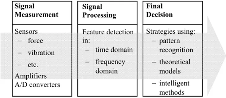
Figure 1- Main steps in a TCM system.
In the last decade the application of TCM systems was widely diffused and many methods have been experimented in recent years [4], especially in case of drilling. The strong interest in applying these monitoring techniques is justified by several reasons:
- about 40% of all chip removal processes are represented by drilling operations, with tool diameters usually ranging between 1 and 20 mm. Therefore, TCM systems applied in drilling represent an important opportunity to reduce machining costs;
- the breakage of a drill during machining usually determines the discarding of the workpiece. The use of a TCM system able to replace the drill before the end-of-life could be very helpful;
- in drilling of small holes (1 to 5 mm) the problem of tool breakage is very critical. For this reason, conservative criteria are usually adopted to select feed rates, leading to low material removal rates and, therefore, low productivity. An adaptive
Signal Measurement Sensors − force − vibration − etc. Amplifiers A/D converters Signal Processing Feature detection in: − time domain − frequency domain Final Decision Strategies using: − pattern recognition − theoretical models − intelligent methods
control of cutting parameters by means of a TCM system could represent an attractive solution to optimise tool life.
2.2 TOOL CONDITION MONITORING: A GENERAL OVERVIEW
It should be clear that describing or interpreting a tool condition means to have a set of structured information to be collected in space and time and intelligently interpreted to have an effective representation of the true state. It is clear that sensors themselves are not effective, if the interpretation of their signals is not appropriately performed.
Therefore, an intelligent TCM system should assure 3 main functions, as in figure 1:
- measurement of signals related to the tool status, revealed by data coming from
sensorial devices; significant to this aim are the placement of sensors and the time frame;
- signal processing for detecting and extracting pertinent data from sensors, those
useful to form a clear view of tool features at a given status, also with respect to its evolution;
- final decision, taken according to a pre-defined strategy, on the basis of all the
information collected and elaborated to reconstruct significant features. It is here that ‘intelligence’ might play an important role for an effective optimisation, in the adaptive nature and reactive feature of the decision making system.
As concern the first phase, the measurement of the extracted signals can be made using different approaches: i) direct measurement, where signals are directly related to the tool status (direct measurement of wear area or direct detection of cutter breakage); ii) an indirect measurement, where the signals are indirectly related to the tool status (measurement of cutting forces and torques, acquisition of acoustic emissions, etc.).
Another classification of sensors can be made according to the position of the sensing device with respect to the cutting tool. Figure 2 synthesizes the different solutions that can be considered for signal measurements. It is generally true that sensing positions closer to the cutting zone guarantee clearer and more reliable signals but, on the contrary, these introduce some problems related to: i) sensor integrity in an aggressive environments; ii) reduction of the available workspace due to the presence of devices, cables, etc.
Signal processing can be mainly performed in the time domain or in the frequency domain. In the first approach, the elaboration consists in deriving either deterministic (maximum and minimum values, areas, etc.) or statistical indices (variance, kurtosis, skewness, etc.), as well as using time series (or predictors). In this latter method, measured signals are used to predict the next value; a process anomaly can be detected if the difference between the measured and the estimated signal is greater than a predefined limit. In the frequency domain different methods can be used, such as Fast Fourier Transform (FFT) and Wavelet Transform; the scope here is to extract the predominant frequencies of the signal and to compare them with reference values. All these information contribute to form a picture of the true tool status, made of pieces (or segments) of information to be interpreted later. Data collected on tool condition does mean nothing if not appropriately related to space and time where they have been collected, as well the methodology of their collection. In the next paragraph these elements will be addressed for the scope of the present analysis of addressing the technical requirements for a reliable and effective TCM.
As concern the third function of a TCM, decisions concerning the tool status can be driven according to different strategies, on the basis of the segments of information available. For instance, when using pattern recognition methods the information extracted in the previous step form a feature that can be compared with a reference pattern: the intelligence of the system should consist in its ability to take a decision according to the similarity. Interesting approaches to this concern are based on the use of intelligent computation methods. Many contributions in this field are based on Artificial Neural Networks (ANNs), where inputs are typically represented by signal features (average value, variance, etc.) and outputs by estimated tool conditions (new tool, worn tool, tool breakage, etc.).
2.3 SINGLE MEASUREMENT APPROACHES IN DRILLING
As mentioned before, the capability of monitoring drill status has a strong economic potential, since large benefits can be obtained exploiting the effective tool-life once the decay mechanisms have been understood. A large amount of researches were devoted to this topic in the last decades. Particularly in automated production systems, it is very interesting to address measurement of drill-status, which directly influences surface finish and dimensions of the manufactured holes.
Each segment of the same type of information can be obtained by one or more measurement systems, being the measurement system a sensor, a probe or any similar devices mounted on the machine tool, or on the tool or on the workpiece. The measurement of tool wear in drilling operations differs from other operations since models of orthogonal and oblique cutting used for turning or milling do not apply, since cutting speed and rake angle vary along the cutting edge, depending on the feed rate. Drills, like other cutting tools, can fail either from breakage or
excessive wear; it has been determined that drills of a diameter less than 3 mm tend to fail by fracture [5], while larger tools fail after a progressive decay due to wear phenomena. In addition, a complex three dimensional material-removal process takes place, when the chip flow creates significant friction between the cutter and the workpiece inside the drill hole. Frictional stresses can significantly change the dynamics of the process and can induce sudden failures, particularly when the hole depth exceeds 2-3 times the drill diameter and almost no cutting fluid can reach the drill tip ([6], [7]). The sudden rise of temperature in the cutting zone in such cases acts to softening the drill tip, causing variations on the tool geometry and of the edge shape, more remarkably than in turning and milling processes.
In principle, the measurement of twist drill wear (i.e. the change in the geometric features), requires several information, and thus several sensing apparatus. Tools wear, i.e. the decay of geometrical and mechanical features of tools, can be detected by collecting different information; up to now, the type of information collected concerned direct measurements (on the tool) and indirect measurements (the effect of wear). Direct methods such as visual inspection (or computer vision) return data of the tool wear as such, by a periodic monitoring of the progressive status of the drill shape and cutting edge status. On the other hand, indirect methods are based on the monitoring of parameters which are correlated with the progress of decay mechanism, e.g. acoustic emission, chattering of the tool-workpiece system, cutting forces or torque and power absorbed by the machine tool. As also reported by Kurada and Bradley [8], in both direct and indirect methodologies, sensors should respect some specific requirements to be successfully applied in a machining environment:
1. signals should be directly related to tool condition;
2. sensor should offer a fast response to be used for a just in time control; 3. sensor design must assure at the same time high stiffness and low overall
dimensions hindering interference with the machining process; 4. contact-free detection should be preferred.
Sensors play a vital role in the acquisition of information relating to the machine, process and workpiece to optimize the machine tool performance. In the case of unsupervised machining, it has been demonstrated that the addition of sensor capabilities can dramatically reduce down times and improve product quality ([9], [1]); this is true especially in the case of deep-hole manufacturing affected by drill clogging and sudden breakage. Sensors for TCM can be categorized also according to the time feature of data collected: on-line (or in-cycle) sensing concern the frequent acquisition of data during the process, thus requiring a large amount of measurement cycles; on the other hand, in-process sensing requires low frequency acquisitions, such as between machining idle times or during part changeovers.
2.3.1 Direct measurements
Realising the change in tool geometry or tool properties during tool-life means to get information on the progress of wear on outer corners and cutting edges in a drilling tool. This can be easily monitored by ranging the progressive increase of characteristic wear parameters directly on the drill tip. Anyway the continuous monitoring of the system tool-workpiece-machine during the material removal leads
to an on-line control which is especially desirable in drilling. Monitoring methods should possibly offer accurate measurements according to the physical principles available.
Further restrictions onto the application of the most common direct sensing techniques for drill wear monitoring is due to the fact that the cutting zone is not accessible for direct measurements, especially in case of deep hole machining. For this reason proximity sensors, which normally estimate tool wear by measuring the change in the distance between the tool’s edge and the workpiece, cannot be used. Furthermore reductions of drill diameter or rounding of the cutting edges are not appraisable with these sensors.
Also the implantation of small amounts of radioactive material on the flank face of the cutting tool, which has been tested in turning operations, seems to be not applicable in drilling. The difficulty in collecting chips out of the machined hole in order to monitor the transferred quantity of radioactive material hinders a correct monitoring of tool wear.
Among direct measurements, system vision sensors represent one of the most diffused method, as already demonstrated in previous researches [10]. In general, these methods make use of structured lights which make it possible to point out the worn area which offers high reflectivity from the unworn surface. In this way it is possible to reconstruct wear profile on the cutting edges by a simple image processing and the measure flank wear areas by pixel counting after a binarization process (see Figure 3).
Figure 3: Binary image for wear measurements provided by [10].
The determination of outer corner wear requires the projection of a structured light pattern onto the tool, in order to derive tool shape information. Once acquired, the border of the twist delimitates an area whose variation can be linked to outer corner wear and reduction in drill diameter (land wear). Investigations on crater wear of a twist drill are rather difficult by using this direct technique. Helix angle hinders to check the distortion of parallel lines of a projected laser light which conventionally gives a measure of crater depth. As a matter of facts, due to the hostility of the cutting environment, vision sensors are strictly limited and can only be used in an in-process fashion.
A relevant group of direct measurements is represented by optical techniques such as interferometry, laser scattering, projected fringe method (holographic technique).
The difficulty in quantifying crater wear lead to exploit the use of white light interferometry to compare three dimensional data of worn tools with a reference CAD model of the same tool [11]. The elaboration of the gaps between worn and unworn tool allowed calculating the volumetric wear loss in crater and flank regions.
Authors in [12], also made use of a reconstruction of a three-dimensional map of tools (not specifically for drills) using a laser scanning technique; crater wear on tool was “captured and processed using a phase-shift fringe patterns projected on its surface”. The limit of this technique is the requirement of a large number of scanning’s to obtain a map with an adequate resolution.
2.3.2 Indirect measurements
Drill wear is a progressive process of transformation of micro-geometries which takes place at the outer margin of the flutes of the drill due to the intimate contact and elevated temperatures at the tool workpiece contact [13].Under constant cutting conditions, drill failure can be considered a stochastic process due to non homogeneities in the workpiece and drill materials, irregularities in the cutting fluid motion and the asymmetries introduced during the grinding of the cutting edges. For these reasons some indirect methods are more effective for detection of a sudden failure and some are more suited for progressive wear monitoring.
Indirect monitoring methods include firstly the piezoelectric measurements of torque, drift and feed force which are all information related on cutting stresses. It is generally known that cutting forces increase as tool wear increases [14]. This is due to the increase of friction between tool and workpiece. In drilling it is possible to monitor torque, drift forces (lateral forces affecting the workpiece) and the thrust force [15]. During the monitoring of torque and thrust force it is expected that these physical parameters change as the tool gradually change shape due wear. The thrust force has been used as the only measured signal in [13], [16], [17] and [18], while its simultaneous monitoring with torque is rather common as reported in [19], [20], [15], [21] and [22]. Due to production tolerances, a drill might be slightly asymmetric: it might happen that it only wears at one lip until the height of both lips is equal [5] [23]. When the second lip, which is then sharper, starts cutting, it generates an alternating process. This behaviour continues until no one lips have more clearance at the margin, bringing the drill to stick into the workpiece. Due to this reasons, in a series of experiments [24] no consistent change of feed force or torque was observed, except of a certain variation in drift forces.
In [25], torque and thrust force were monitored in drilling of cast iron using HSS tools, as functions of drill wear. Formulas defining thrust and torque as a function of feed per revolution, drill diameter and flank wear, have been developed and their reliability was tested also in following researches [13]. Tests indicated that, in case of metal drilling, the increase of in cutting speed had no significant effect on work material strength, and hence it did not generate variations in cutting forces.
These considerations might change significantly in case of drilling of composite materials, where high cutting speeds combined with the abrasive action of reinforcements (e.g. glass or carbon fibres) can drastically increase drill tip temperature, thus inducing remarkable variations in tool shape and consequently of cutting forces.
A second group of indirect measurements is represented by spindle motor and feed drive current monitoring. The first one is in principle a measure of the same feature as torque, i.e. they both enlighten how much power is used in the cutting process and they both also advise about the dynamics of cutting. A comparison of these two sensing systems can show significant differences. Torque sensors represent always a more sensitive way to measure wear, since they are located closer to the tool, while signals obtained by spindle current monitoring (e.g. by Hall-effect sensors) are usually influenced by noises in the measuring chain. On the other hand the method of reduction of tool-shaft diameter, whose deformation then allows torque measurements in eddy-current sensors, can slightly reduce the stiffness of the system toolworkpiece. Authors in [26] estimate the tool state in drilling operations analyzing spindle and feed motor currents: the authors found an almost linear incremental relationship between measured currents and tool wear state, characterised by flank wear and drill diameter. The presence of disturbances in supplied electrical power led Fu et al. [27] to monitor the electrical impedance of the spindle motor instead of current for the on-line breakage detection during micro-drilling. Szecsi [28] suggested the monitoring of the armature current of the main motor, not specifically for drilling operation, to measure the main cutting force that, together with the other two cutting forces components (thrust and radial force), affect the tool flank wear.
As a matter of fact, the measurement of the current has also been widely tested in literature (see [25], [26] and [29]) and seems to be a more conservative approach for industrial applications. The major advantage of using current signal measurements to assess drill state is that the measuring device does not affect the machining process.
A third type of drill wear measurements is related to vibrations, sound, ultrasonic vibration and acoustic emission; these can be classified by their frequency range [30]. Sound is an airborne vibration, despite all the other vibrations which originates mechanically by the structure workpiece-tool-machine. The frequency in vibration measurements ranges typically from about 1 Hz to about 10 kHz. Sound measurements range from 20 Hz to 20 kHz (the human hearing capability), while in ultrasonic emission (UE) the frequency range is from 20kHz to about 80 kHz [9]; acoustic emission (AE) starts where ultrasonic vibration ends up and ranges to about 1MHz.
Some information on the drill state can also be collected by other indirect measurements: the texture analysis of manufactured surfaces using vision systems. In [31] an investigation study is provided. A fundamental hypothesis for this technique is that “the surface features generated by the wear of the tool can be separated from the other factors” such as feed rate, spindle speed, machine tool alignment, and tool setup. The surface texture generated by the machining process is analysed by a power spectral density method. Comparing the intensity profiles of a worn and a new tool, allows detecting the irregularities in the reflection pattern which characterized the profile of a worn tool.
2.4 MULTIPLE SENSORS TCM
As above stated, evaluating the decay process of a tool means to reconstruct multiple segments of information, collected and recomposed appropriately to form
a multiple-view: this latter might allow more realistic and effective representation of reality.
To do so, it is necessary to derive all the segments of information related to the technological process, to the tool and to the machine tool. In the preceding paragraphs several techniques have been analysed; each one used independently provides a single-view tool condition monitoring. Whenever more than one technique is used to derive information, about the tool or the process, one can talk of multi-view tool condition monitoring system. The requirements that should be afforded by such a technique should complement those already cited at the beginning of paragraph 3:
• the increase of the forecasting accuracy [32];
• avoid false alarms and consequently machine tool downtime; • to reach an higher productivity and parts quality;
• to obtain a TCM i) fault tolerant through redundancy, ii) complementary (disparate sources which provide amore global view of the technological process) and iii) cooperative (one information source relies or cooperates with others) [33].
As stated before, several types of information can be involved in this multiple-view system, related to the time domain: on-line and in-process, referring typically to the rate of variation (high or low). Monitoring can be also defined according to the place of acquisition of data; this fact may change the cost of the monitoring system or even the feasibility of it, if jointly considered with time feature. A real time measurement during the machining process requires always more effort, also in term of online data processing.
As a final remark, technological or physical principles of sensors are another important factor for TCM: it can be a critical point for sensor fusion, which anyway requires data elaboration. A multi-view TCM system may include and/or integrate easily sensors sharing the same technology or physical principle. In this latter case, information collected in each state is structured in information segments which are congruent, and thus easily interpretable to forecast the tool decay mechanisms. Whether different physical principles are used for TCM, greater difficulties may rise in the coherent interpretation of data. Integrating data contained in each information segment, in fact, should enable to represent adequately the complexity of the drilling process, better than a single system acquisition. The cost of this increase of information should be carefully considered and compared to its scopes. Forming the multiple view means to process information sources using sensor fusion, i.e. data fusion techniques [34]: to a certain extent one can talk about the need to interoperate sensors to manage such a complex system. In principle, a higher decision-making capability can be achieved through a tool state monitoring performed by such a multifaceted information model; this should grant “to extract
multiple interrelated parameters from every part of the machine so as to reach a significant conclusion” [35]. On the other hand, the increase of information is paid
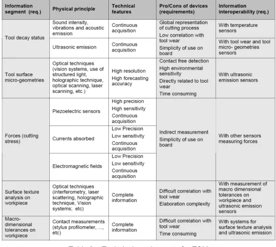
by a higher complexity of the physical system as well as the stability, or even the reliability, of the multi-view TCM system. It is thus a matter of balancing these two main criteria depending on different situations and the nature of technology. Table 1 summarizes characteristic information types for tool condition monitoring classified according to the information segment typology (static and dynamic) as well as the information nature: the former refers to the time frame in which
information can be collected (e.g. dynamic is during the action) while the latter refers to the cause generating the information (i.e. interaction between two elements in the cutting process or one element alone). The location of data acquisition (indicated in bracket) stands for the physical place where data are retrieved.
Table 1- Physical principles for TCM.
Several research activities related to TCM available in literature reconstruct segments of information by the use of multiple sensors. In fact, information from multiple sensors signals is differently correlated to the tool status at different levels of tool wear [36]; this fact may reflect different aspects of tool-failure activities (microscopic activities such as stress waves, or macroscopic ones such as vibration). Authors in [37] showed the sensitivity of tool condition monitoring to different wear localizations(flank, crater, chisel edge, etc.) and wear mechanisms(adhesive, diffusion, abrasion, etc.).
Several structures of multi-view TCM have been designed and developed so far, based on the utilization of different linear combination of sensors: rarely information provided by different sensors is analyzed jointly, and thus a real fusion among sensors is provided. The most of the times, sensors are treated independently as their information derived, reasonably for the congruence reasons above stated. A multi-sensors approach in drilling was proposed by [38] using four sensors: thrust, torque and two piezoelectric strains elements (located in the X- and Y- directions of machine table). Time and frequency domain analyses of the signals were
conducted showing a good correlation (i.e. significant changes observed between worn and sharp tool) of the sensor signals with drill wear only in the frequency domain. The change in the area under the power spectral density plots of each of the four sensor signals plotted against the total corner showed a good correlation of drill wear with thrust, torque and strain in X direction while a weak correlation was detected in Y direction.
Authors in [39] realized an intelligent recognition of drill status, monitoring two signals: vertical acceleration measured by an accelerometer and thrust force detected by a dynamometer. Figure 4 schematically represented the experimental set up proposed by authors.
Figure 4 – Schematic representation of the experimental set up proposed in [39].
The normalized increases of the peak-to-peak amplitude of vertical acceleration and the drilling thrust were used as inputs for an input layer of a feed-forward neural network; the output layer of the networks gives the wear status of a drill classified into five different category (initial wear, slight wear, moderate wear, severe wear and worn out). The authors also justified the realized sensor fusion comparing results provided by the use of the two previous reported sensors to ones provided by the use of percent increase in drilling thrust only. Results showed that the rate of success of the former is higher than the rate of the latter.
Lin and Ting [20] performed an on-line drill wear monitoring, measuring the thrust force and torque signals. The least squares method was adopted to obtain a functional dependence of torque and thrust force on various cutting parameters. This is a further example of how a simpler multi-view TCM is adopted in literature, to avoid complex data elaboration and also for significance of final information. Kim and Choi [40] developed a true multi-view TCM proposing a sensor fusion algorithm to integrate signals from multi-sensors in order to realize a tool breakage detection, not specifically for drilling. The algorithm integrates three signals: cutting force, acceleration and displacement (for relative oscillation between tool and workpiece). The deviation of average cutting force, the peak value of acceleration and the displacement were monitored in order to decide the action and transmit
control commands to the action parts. Values exceeding threshold (adapted according to the cutting condition) for each parameter represent tool breakage status. Test performed by authors on the algorithm, showed a success rate up to 90%.
Al-Habaibeh et al. [41] also performed an integrated multi-view TCM system by integrating machine and process condition monitoring for drilling, milling, turning and grinding. Authors realized an experimental set-up schematically represented in Figure 5, constituted by accelerometers on the workpiece, an acoustic emissions sensor, a dynamometer, a thermocouple on the workpiece and a spindle load sensor. The authors proposed both an on-line and off-line condition monitoring. The off-line part concerns data related to the machine status and is based on standard test such as laser interferometer system and Ball bar test for testing the configuration and calibration of the machine. The online monitoring is related to cutting process and machine status; signals monitored were, namely: the servo motor current of all the axes, the coolant pressure, temperature, and flow rate, cutting forces, torque, vibration, acoustic emission, temperature and spindle load.
Figure 5 - Schematic representation of multi sensors TCM proposed by [41].
The analysis conducted on sensors signal, enhanced that some signals are useful for detecting the gradual tool wear (in particular spindle load, thrust force and drilling torque) while others are less sensitive. Authors also highlight that results are probably limited to the particular drilling process and the selected cutting parameters.
2.4.1 Intelligent data treatment for multiple sensors TCM
The interoperation of different sensors involves integration and fusion of their signals for detecting and extracting significant features from data collected. Signals of different sensors are collected and subsequently elaborated and fused through various computation methods such as statistical methods, rule-based fuzzy sets,
genetic algorithms, auto-regressive models and different architectures of Artificial Neural Networks.
An exhaustive description of the use of ANN-based sensor fusion for tool wear estimation is provided by [36]. To assess the performances of two different types of ANN, (namely back-propagation neural network and radial basis function network) in predicting the drill flank wear, a study has been carried out by [42]. Process parameters provided as input for either of the networks were: thrust force, torque, feed rate, drill diameter, spindle speed and chip thickness while networks output was the corresponding maximum flank wear.
The correct recognition rate of three different combinations of couple of sensors (acoustic emissions and forces, acoustic emissions and vibrations, vibrations and forces) for drill wear/failure monitoring was exploited by [43]. The recognition rate was calculated adopting two different architectures of ANN for sensor fusion: a multilayer feed-forward network and a single category based classifier. Results showed that the latter network was the best choice for decision making while the combination of acoustic emissions and force signals is “insensitive to the changes of the cutting conditions and can operate over a wide range of cutting parameters”. As showed in previous studies the adoption of ANN based method for sensor fusion has gained more attention in recent years, primary due to the simplicity deriving from the absence of a specified model of the process under analysis [44]. This model-free feature allows the emergence of an output from data, thus making the whole analysis process simpler and effective. In fact, ANN-based method allows making quickly decisions also in presence of incomplete and noisy information.
Whether more complex information structures might be addressed, it may result questionable if ANN still continue working as an interoperability agent or if a further data pre-treatment is required to integrate their meaning, for instance by recurring to complex process models.
2.5 FUTURE TRENDS AND CONCLUSIONS
Drilling is still a very complex process to predict, due to the number of factors contemporary present. Single tool condition monitoring, direct or indirect, on-line or in process, seldom might bring to an exhaustive view of the process for the optimisation purposes in tool management. Partial segments of information, in fact, cannot afford a good control or even knowledge of phenomena underlying. On the other hand, simplicity and installation costs should be considered to compare different solutions of sensor fusions.
Tool condition monitoring can be improved by multiple view TCM whenever more reliable approaches or data integration strategies can be developed. New challenges will be then to be faced: the interoperation of devices, the way data acquisition and processing techniques will support decision making. This problem can be characterised as “interoperability of measurement systems”, that it is reasonable to become a new challenge of the future research in tool condition monitoring.
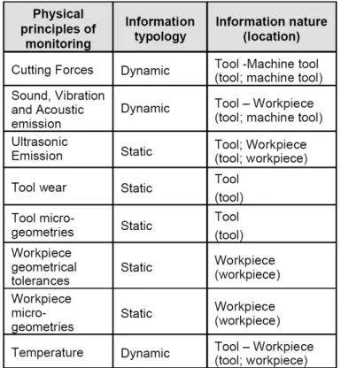
As a concluding remark, the following table 2 summarises the technical requirements that should be satisfied by an effective and reliable TCM system for drilling. Column 1 provides general requirements, while column 4 gives requirements for single TCM. The last column provides challenges for multi-view
TCM, hopefully to be explored in the future to obtain more reliable and effective devices tool decay analysis, which is always a matter of process quality control or cost reduction.
Table 2 – Technical requirements for TCM.
2.6 REFERENCES
[1] Byrne, G., Dornfeld, D., Inasaky, I., Ketteler, G.,König, W., Teti, R., 1995, Tool Condition Monitoring(TCM) – The status of research and industrial application, Annals of the CIRP, 44/2: 541-567.
[2] Teti, R., 1995, A review of tool condition monitoring literature data base, Annals of the CIRP, 44/2: 659-666.
[3] Kuljanic, E., Sortino, M., 2002, Recent trends and developments in tool condition monitoring,Proceedings of AMST, 15-36.
[4] Jantunen, E., 2002, A summary of methods appliedto tool condition monitoring in drilling, International Journal of Machine tool & Manufacture, 42: 997-1010.
[5] El-Wardany TI, Gao D., El-bestawi M.A., 1996, Tool condition monitoring in drilling using vibrationsignature analysis, International Journal of Machine Tool & Manufacture, 36/6: 687–711.
[6] Kubota, H., Tabei, H., 1999, Drilling of a small and deep hole using a twist drill, Transactions of the Japan Society of Mechanical Engineers, Part C 62(601): 3691–3697.
[7] Heinemann, R., Hinduja, S., Barrow, G., Petuelli, G., 2006, Effect of MQL on the tool life of small twist drills in deep-hole drilling, International Journal of Machine Tools & Manufacture, 46: 1–6.
[8] Kurada S., Bradley C., 1997, A review of machine vision sensors for tool condition monitoring, Computers in Industry, 34: 55-72.
[9] Death, M., 1986, Sensors: Keys to automation, Manufacturing Engineering, 96/6: 54.
[10] Santochi, M., Giusti, F., Tantussi, G., Dini, G., 1993,Tool wear monitoring of twist drills by image analysis, Proceedings of AMST, Udine April 26-271993, vol. 2 :79-86.
[11] Dawson, Ty G., Kurfess, T. R., 2005, Quantification of tool wear using white light interferometry and three-dimensional computational metrology, International Journal of Machine Tools &Manufacture, 45: 591–596.
[12] Wang, W.H., Wong, Y.S., Hong, G.S., 2006, 3Dmeasurement of crater wear by phase shifting method, Wear, 261: 164–171.
[13] Thangaraj, A., Wright, P.K., 1988, Computer assisted prediction of drill-failure using in-process measurements of thrust force, Journal of Engineering for Industry, Transactions of the ASME,110: 192–200.
[14] König, W., Christoffel, K., 1980, Sensoren für die Bohrbearbeitung, Industrie Anzeigner, 103/100: 29–33.
[15] Li, P.G., Wu, S.M., 1988, Monitoring drilling wear states by a fuzzy pattern recognition technique, Journal of Engineering for Industry, Transactions of the ASME, 110/2: 297–300.
[16] Tansel, I.N., Mekdeci, C., Rodriguez, O., Uragun, B.1993, Monitoring drill conditions with wavelet based encoding and neural network, International Journal of Machine Tools & Manufacture, 33/4: 559–575.
[17] Tansel, I.N., Rodriguez, O., Mekdeci, C., 1992, Detection of tool breakage in microdrilling operation with RCE neural networks, PED, ASME, 47/1: 83–88. [18] Von Nedeß, C., Himburg, T., 1986, AutomatisierteÜberwachung des Bohrens,
VDI-Z, Bd 128/17: 651–657.
[19] Kavaratzis, Y., Maiden, J.D., 1989, System for real time process monitoring and adaptive control during CNC deep hole drilling, Proceedings of Comadem‘89, Kogan Page, London, UK, 148–152.
[20] Lin, S.C., Ting, C.J., 1995, Tool wear monitoring in drilling using force signals, Wear, 180/(1-2): 53–60.
[21] Liu, T.I., Anantharaman, K.S., 1994, Intelligent classification and measurement of drill wear, Journal of Engineering for Industry, Transactions of the ASME, 116:392–397.
[22] Routio, M., Säynätjoki, M., 1995, Tool wear and failure in the drilling of stainless steel, Journal of Materials Processing Technology, 52/1: 35–43. [23] Braun, S., Lenz, E., Wu, C.L., 1982, Signature analysis applied to drilling,
[24] Lenz, E., Mayer, J.E., Lee, D.G., 1978, Investigation in drilling, Annals of the CIRP 27/1: 49–53.
[25] Subramanian, K., Cook, N.H., 1977, Sensing of drill wear and prediction of drill life (I), Journal of Engineering for Industry, Transactions of the ASME101: 295–301.
[26] Li, X., 1999, On-line detection of the breakage of small diameter drills using current signature wavelet transform, International Journal of Machine Tools &Manufacture 39/1: 157–164.
[27] Fu, L., Ling, S., Tseng, C., 2007, On-line breakage monitoring of small drills with input impedance of driving motor, Mechanical Systems and Signal Processing, 21: 457–465.
[28] Szecsi, T., 1999, A DC motor based cutting tool condition monitoring system, Journal of Materials Processing Technology, 92-93: 350-354.
[29] Jantunen, E., Jokinen, H., 1996, Automated On-line Diagnosis of Cutting Tool Condition (Secondversion), International Journal of Flexible Automation and Integrated Manufacturing 4/(3-4): 273–287.
[30] Everson, C.E., Cheraghi, S.H., 1999, The application of acoustic emission for precision drilling process monitoring, International Journal of Machine Tools & Manufacture, 39: 371–387.
[31] Bradley, C., Wong, Y. S., 2001, Surface Texture Indicators of Tool Wear – A Machine Vision Approach, International Journal of Advanced Manufacturing Technology, 17: 435–443.
[32] Rubio, E.M., Teti, R., Baciu, I.L., 2006, Main decision making procedures used in the monitoring systems of machining processes based on acoustic emission sensors, 6th CIRP Int. Conf. on Intelligent Computation in Manufacturing Engineering – CIRP ICME ’04: 189-192.
[33] Edan, Y., Nof, S.Y., 2000, Sensor economyprinciples and selection procedures, IIETransactions, 32: 195-203.
[34] Sasiadek, J.Z., 2002, Sensor fusion, Annual Reviews in Control, 26: 203-228. [35] Hu, W., Starr, A., Leung, A., 2001, A multisensory based system for
manufacturing process monitoring, Proc Instn Mech Engrs, 215/B: 1165-1175. [36] Ghosh, N., Ravi, Y.B., Patra, A., Mukhopadhyay, S.,Paul, S, Mohanty, A.R.,
Chattopadhyay, A.B., 2007,Estimation of tool wear during CNC milling using neural network-based sensor fusion, Mechanical Systems and Signal Processing, 21: 466–479.
[37] Quan, Y., Zhou, M., Luo, Z., 1998, On-line robust identification of tool-wear via multi-sensor neural network fusion, Engineering Applications of Artificial Intelligence, 11: 717-722.
[38] Noori-Khajavi A., Komandurit, R., 1994, Frequency and time domain analyses of sensor signals in drilling-I. correlation with drill wear, International Journal of Machine Tools and Manufacture, 35/6:775-793.
[39] Liu, T.L., Chen, W.Y., Ko, E.J., 1994, Intelligent Recognition of Drill Wear States, JMEPEG, 3:490-495.
[40] Kim, J., Choi, I.,1999, Development of a tool failure detection system using multi-sensors, International Journal of Machine Tools & Manufacture, 36/8: 861-870.
[41] Al-Habaibeh, A., Liu, G., Gindy, N., 2002, Sensor usion for an integrated process and machine ondition monitoring system, 15th Triennial World ongress, Barcelona, Spain.
[42] Garg, S., Pal, S.K., Chakraborty, D., 2007,Evaluation of the performance of back propagation and radial basis function neural networks in redicting the drill flank wear, Neural Computer &Application, 16: 407–417.
[43] Hermann, G., 2003, Application of Neural Network Based Sensor Fusion in Drill Monitoring. First Slovakian-Hungarian Joint Symposium on Applied Machine Intelligence (SAMI) - Herlak (Sk).
[44] Teti, R., Baciu, I.L., 2004, Neural network processing of audible sound signal parameters for sensor monitoring of tool conditions, 4th CIRP Int. Conf. on Intelligent Computation in Manufacturing Engineering – CIRP ICME ’04, Sorrento, 30 June – 2 July: 385-390.
![Figure 2 – Different measurements adopted in Toll Condition Monitoring [1].](https://thumb-eu.123doks.com/thumbv2/123dokorg/7377853.96206/3.723.129.573.578.859/figure-different-measurements-adopted-toll-condition-monitoring.webp)
![Figure 3: Binary image for wear measurements provided by [10].](https://thumb-eu.123doks.com/thumbv2/123dokorg/7377853.96206/6.723.263.460.467.657/figure-binary-image-wear-measurements-provided.webp)
![Figure 4 – Schematic representation of the experimental set up proposed in [39].](https://thumb-eu.123doks.com/thumbv2/123dokorg/7377853.96206/11.723.175.548.284.552/figure-schematic-representation-experimental-set-proposed.webp)
![Figure 5 - Schematic representation of multi sensors TCM proposed by [41].](https://thumb-eu.123doks.com/thumbv2/123dokorg/7377853.96206/12.723.153.576.382.667/figure-schematic-representation-multi-sensors-tcm-proposed.webp)