UNIVERSITA’ DEGLI STUDI DI PISA
FACOLTA’ DI INGEGNERIA
Corso di Laurea Specialistica in Ingegneria delle
Telecomunicazioni
Tesi di Laurea Specialistica
''Methods for improving energy efficiency in TDM PONs''
RELATORI: CANDIDATO:
Prof. Stefano Giordano Michele Chincoli
Ing. Rosario Giuseppe Garroppo Ing. Luca Valcarenghi
Ing. Paolo Monti
CONTENTS
Abstract
Riassunto analitico
Chapter 1 – INTRODUCTION
1.1 Overview 1
1.2 Passive Optical Network 2
1.2.1. EPON 6
1.3 Energy consumption 10
Chapter 2 - APPROACHES FOR SAVING ENERGY IN PASSIVE OPTICAL NETWORKS
2.1 Classification 13
2.2 Physical layer solutions 14
2.3 Data link layer solutions 18
2.4 Hybrid solutions 21
Chapter 3 – SAVING ENERGY METHODS
3.1 Introduction to the approach 23
3.2 SPW operation 23
3.2.2. Service-based algorithm 27
Chapter 4 – RESULTS
4.1 Scenario 33
4.2 Interarrival-based algorithm 34
4.3 Service-based algorithm 37
Chapter 5 – CONCLUSIONS AND FUTURE WORK 42
Abstract
Even though Information and Communications Technologies (ICT) are currently consuming between 2% and 4% of the electricity consumed worldwide, the number of efforts devoted to reduce the communications network energy consumption is increasing. This is mainly due to the foreseen growth of ICT even in substitution of personal travel. Access networks are the network segment that currently consumes the highest percentage of energy. Even though the utilization of optical technologies can potentially reduce the energy consumed by current ADSL modems, the further reduction of the energy consumed by passive optical access networks (PON) is attracting a lot of interests.
Previous studies showed that, in PONs, the majority of the energy in consumed by the customer premises equipments, i.e. the Optical Network Units (ONUs), because of the many idle periods used only for synchronization. For this reason the target of our work is to save energy by exploiting cyclic sleep periods in the ONU. In particular the Sleep and Periodic Wake-up (SPW) technique is considered. The SPW mechanism is managed by the OLT and the choice of the sleep period for the ONUs can be based on different parameters. In this work two approaches are considered for deciding the sleep period: interarrival-based and service-based.
The interarrival-based approach has been previously presented. In this thesis a simulator based on Opnet Modeler is built to verify the validity of the previously presented results. Then a novel service-based sleep time scheme is designed and evaluated. The novelty of our work resides in presenting a service-based saving energy technique with variable sleep period to maximize the energy efficiency guaranteeing the maximum tolerable delay of the applications subscribed by the ONU.
The main difference between the two approaches is how the sleep period is set. Following SPW technique, the OLT sets the sleep period according to traffic conditions such as average frame interval and queue length in the interarrival-based algorithm, and class of service (CoS) in the based algorithm. In the interarrival-based the sleep period is fixed, instead in the service-based the sleep period changes in function of the delay constraints of subscribed services to guarantee the service performance.
The simulation results in the interarrival-based approach are very similar to the published ones. In case of low and high bandwidths, the values of average power are matched, instead the values of average queuing delay differ because of reasonable different assumptions. The increasing trend are the same in both results.
The service-based approach resulted in the average frame delay, which exploits the maximum tolerable delay maximizing the energy efficiency. The SPW technique with service-based approach was presented in the Optical Fiber Communication Conference and Exposition (OFC) 2012 in Los Angeles.
Riassunto analitico
Sebbene le Tecnologie di Informazione e Comunicazione (ICT) consumino ad oggi tra il 2% e il 4% del consumo di elettricità mondiale, il numero di sforzi mirati alla riduzione del consumo energetico delle reti di comunicazione è in aumento. Questo è maggiormente dovuto alla prevista crescita di ICT anche in sostituzione agli spostamenti fisici. Le reti di accesso sono la porzione di rete che attualmente consuma la più alta percentuale di energia. Anche se l'uso di tecnologie ottiche possono potenzialmente ridurre l'energia consumata dai correnti modem ADSL, la conseguente energia consumata dalle reti di accesso passive (PON) attrae molto interesse.
Studi passati mostrano che, nelle PON, la maggior energia è consumata dalle apparecchiature di utenza, per esempio, le unità di rete ottica (ONU), a causa dei molti periodi di inattività usati solo per la sincronizzazione. Per questo motivo, l'obiettivo del nostro lavoro è il risparmio energetico sfruttando periodi ciclici di sleep nelle ONU. In particolare la tecnica Sleep and Periodic Wake-up è presa in considerazione. Il meccanismo SPW è gestito dall'OLT e la scelta del periodo di sleep per le ONU si può basare su diversi parametri. In questo lavoro due approcci sono considerati per decidere il periodo di sleep: interarrival-based e service-based.
L'approccio interarrival-based è stato presentato in precedenza. In questa tesi un simulatore basato su Opnet Modeler è implementato per verificare la validità dei risultati precedentemente presentati. Successivamente un nuovo schema service-based con periodi di sleep è stato progettato e valutato.
L'originalità del nostro lavoro consiste nella presentazione di una tecnica per risparmio energetico service-based con periodi di sleep variabile per massimizzare l'efficienza energetica garantendo il massimo ritardo tollerabile delle applicazioni a cui l'ONU è abbonato.
La principale differenza tra i due approcci riguarda come il periodo di sleep è impostato. Seguendo la tecnica SPW, l'OLT imposta il periodo di sleep in base alle condizioni di traffico come il tempo d'interarrivo medio e la lunghezza della coda nell'approccio interarrival-based, e come la classe di servizio (CoS) nell'approccio service-based. Riguardo l'interarrival-based il periodo di sleep è fisso, invece nel service-based il periodo di sleep cambia in funzione del limite di ritardo imposto delle applicazioni per garantire le prestazioni di servizio.
I risultati delle simulazioni nell'approccio interarrival-based sono molto simili a quelle pubblicate. Nel caso di basse e alte bande, i valori di potenza media combaciano, mentre i valori di ritardo di accodamento medio differiscono a causa di diverse assunzioni. L'andamento delle curve è lo stesso.
L'approccio service-based con risultati riguardo il ritardo medio dei pacchetti, sfrutta il massimo ritardo tollerabile per massimizzare l'efficienza energetica.
La tecnica SPW con approccio service-based è stato presentato all'Optical Fiber Communication Conference and Exposition (OFC) 2012 a Los Angeles.
1 – INTRODUCTION
1.1 - Overview
The thesis work proposes the development of new sleeping techniques for energy efficiency in Time Division Multiplexing (TDM) Passive Optical Networks (PONs). The work was made at the NEGONET, group at the Royal Institute of Technology (KTH) in Kista (Stockholm) and at the laboratories of the Institute of the Communication, Information and Perception Technologies (TeCIP) of the Scuola Superiore Sant'Anna.
Saving energy is an important field in which many researchers are working to find new and improved techniques. It's not only an academia discipline of study but it's also considered by telecom providers with the aim to reduce their operative expanse (OPEX).
As reported in previous research, it becomes obvious that home networks consume the largest share of energy in Telecommunication networks, but concerning the network sections, highest energy consumption shares are observed in the fixed and mobile access networks because of the huge number of distributed network elements in the field. This is mainly due to the high number of involved elements (i.e., the customer premises equipments — CPEs).
In this work, energy efficient techniques are developed for the Ethernet PON architecture with Time Division Multiplexing (TDM).
The tool of simulation used to assess the proposed technique performance is OPNET Modeler.
1.2 - PASSIVE OPTICAL NETWORK
The general structure of a modern telecommunication network consists of three main portions: backbone (or core) network, metro/regional network, and access network (Fig. 1).
The PONs reside in the family of the access networks, called also first-mile networks (or last-mile from a point of view of the core network). The access network is the portion of the whole network developed between the Central Office (CO) to the customer premises.
Fig.1 – Structure of a Modern Telecommunication Network
The optical fiber has the advantage of high bandwidth, low loss, and low noise, thus it is commonly used in the core and backbone network.
Because of the continue bandwidth requirements, the rise of customers and the diffused use of services (e.g., video-on-demand, gaming online and peer-to-peer
data transferring), the providers are expanding the usage of optical fiber to the access networks. Mostly the PONs are referred to the Fiber-To-The-x (FTTx) system, whose “x” is the variable name (e.g., home, cabin, building,...) depending on how the fiber is close to the users.
After more than 20 years of active research, according to [1], PONs are having important deployments in Asia, North America and, less, in Europe.
A PON is a power splitting Point to Multi-Point (PS-P2MP) network with a remote passive splitter, called Remote Node (RN), to share broadcast downstream traffic to the recipients. Basically, the architecture is composed of a shared optical fiber with a unit of management to the CO, the Optical Line Terminal (OLT), and Customer Premises Equipments (CPEs) to the home network, the Optical Network Units (ONUs).
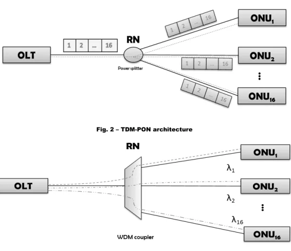
Each OLT is shared by up to 32 ONUs for a maximum separation of 20 km between the OLT and ONU. In the commercial PONs a split ratio of 1:16 or 1:32 is commonly used. The PON architecture can be designed in different structures. About downstream direction, from the OLT to the ONUs, the Time Division Multiplexing (TDM) PON (Fig. 2) and the Wavelength Division Multiplexing (WDM) PON (Fig. 3) are presented. The TDM-PON function is to transmit in separated time slots the traffic to each ONU and the RN used is a passive splitter that broadcast all the packets to all the ONUs. On the other hand, the WDM-PON sends in private channels the traffic to each ONU by different wavelength. The RN, in this case, is a WDM coupler.
Fig. 2 – TDM-PON architecture
Fig. 3 – WDM-PON architecture
The OLT and the ONUs can communicate by two optical fibers or one optical fiber. If two optical fibers reside between the units then the upstream and downstream traffic flow in distinct physical channels and two splitters, for TDM architecture, or two multiplexer couplers, for WDM, are used. Besides, the upstream and downstream traffic are in the same optical fiber and so some solutions are applied. One solution is to separate the different optical signals by simple 3-dB 1:2 directional couplers at the OLT and ONU, using only one wavelength, but the near-end cross talk (NEXT) disturb can occur. In a similar way, the Time Division Duplex (TDD) can be realized, in which the OLT and ONU take turns to use the fiber in a ping-pong fashion for upstream and downstream transmissions. In this situation the NEXT effect is avoided. The last solution is to use the Wavelength Division Duplex (WDD), where upstream and downstream traffic are separated by
two different wavelengths. An example of commercial TDM PON with WDD is in the Fig. 4.
In this architecture, an OLT is connected to the ONUs via a 1:32 splitter. The maximum transmission distance covered is usually 10–20 km. The upstream and downstream traffic are separated by 1.3 μm and 1.49 μm wavelengths respectively. Different OLTs are situated in the CO connected to a switch or cross-connect to the backbone network. The OLTs are constructed by line cards in a chassis in whom also the switch can be hosted.
The portion between one OLT and ONUs is called PON section. The signals transported in this section can be encoded and multiplexed in different formats and schemes depending on the PON standard implemented. Nevertheless, beyond the PON section, standard format signals are used for client interface hand-off, switching, and cross-connect. The most common standard interface used today is the Ethernet interface.
Fig. 4 – Example of Commercial TDM-PON architecture
In a TDM-PON architecture, the traffic, from or to one ONU, is frame interleaved and it is identified by a Logical Link ID (LLID) carried in the preamble. The downstream transmissions are broadcast point-to-multipoint (P2MP), instead the upstream transmissions are multipoint-to-point sharing the same physical medium.
avoid collisions between frames of each ONU, whose transmit traffic in a shared optical fiber to the OLT. The mechanisms is that each ONU has a specific time slot to transmit own traffic and thus it allows to the OLT to have only one receiver.
PON standardizations are represented into two big groups: Ethernet PON (EPON) standardized in 802.3ah by IEEE and Gigabit-Capable PON (G-PON) standardized in the G.984.x and G.987.x ITU-T Recommendations .
The EPON has the main characteristic to encapsulate IP packets in Ethernet frame. On the other hand, it is used a new framing mechanism called G-PON encapsulation mode (GEM), which is based on the original idea of generic framing procedure (GFP).
The EPON architecture is considered in this work and detailed in the next section.
1.2.1 - EPON
EPON is a PON-based network that carries data traffic encapsulated in Ethernet frames as defined in the IEEE 802.3 standard.
Ethernet covers the physical layer and data link layer of the open system interconnect (OSI) reference model. Fig. 5 shows a comparison of the layering model of the traditional point-to-point (P2P) Ethernet and the point-to-multipoint (P2MP) EPON architecture.
The most important difference is the exchanging sublayer of Media Access Control (MAC) to Multipoint Media access Control (MPMC). The MPMC has the task to manage the Multipoint Control Protocol (MPCP) to coordinate the access to the shared PON medium among EPON ONUs .
The stacks of the ONU and OLT differ to the MPCP entity, the first one is a slave and the second one is a master. The MPCP manages by MAC control messages the assignment of the transmission window to each ONU so the upstream transmission can flow without collisions. There are two modes of operation of MPCP: autodiscovery (initialization) and normal operation. In the autodiscovery
mode, the OLT learns the MAC address and the RTT of new joined ONUs if they are detected. Instead, in the normal mode, the OLT assigns the transmission window to the discovered ONUs.
In a PON, the communications from each ONU to a destination pass through a splitter, a passive component that forwards all the frames only to the OLT. For this motivation, the transmissions of each ONU can't be detected from other ONUs. To resolve this issue and to ensure seamless integration with other Ethernet networks, devices attached to the EPON medium will use an extended reconciliation sublayer (RS), which will emulate the point-to-point (P2P) medium. The P2P emulation function is achieved by modifying the preamble in front of the MAC frame to include a LLID that identifies each ONU. The modified preamble with the LLID is used in the PON section.
Fig.5 – P2P Ethernet architecture and P2MP EPON architecture
The PON is a centralized system and the OLT has the role of master. This architecture allows to have simple and chip ONUs that doesn't know the state of
the network and a simple topology P2P from the ONUs to the OLT. These advantages weren't possible in a distributed system because, in the upstream case, an ONU has to monitor the network by communications with the other ONU to know their state of transmission and so send the traffic alternatively without collisions.
In a centralized PON system is not applicable the Carrier Sense Multiple Access/Collision Detection (CSMA/CD) because of the long distance between the OLT and the ONUs (up to 20 km). In the situation of a collision, the ONU could be informed of it after an high delay since the detection to the OLT by sending a jam frame. Thus, the mechanism used not to have collisions is established in MPCP and it consists of a polling scheme exchanging grant and request messages. The MPCP facilitates the implementation of an algorithm to take decisions about the allocation of bandwidth to give for each ONU. The algorithm is known as Dynamic Bandwidth Allocation (DBA); it isn't specific and it's out of scope for the standard. The choice of the DBA is left to equipment vendors.
In the mechanism the OLT would allow only one ONU to transmit at any given time. It manages the assignation of a transmission timeslot setting the startTime and the length values of the slot. The values for startTime and length are decided upon by a DBA agent or scheduler, located in MAC control client, a sublayer outside the scope of IEEE 802.3ah. Afterward the values are passed to the gate process in which a GATE message is built and sent to the ONUs.
The ONU parses and demultiplexes the GATE message which is passed to the gate process that manages the upstream transmission according to the timeslot allocated. In an EPON system, the downstream physical link maintains continuous signal stream and clock synchronization. In the upstream direction, in order to maintain a common timing reference with the OLT, ONUs use loop timing for the upstream burst mode transmission, i.e. the clock for upstream signal transmission is derived from the downstream received signal.
Fig.6 – MPCP scheme
Finally the ONU informs the OLT its local conditions for the next timeslot allocation. It sends a REPORT message containing the amount of traffic to be transmitted in the next polling cycle. REPORT frames can be sent only in previously assigned timeslots. At the OLT, the received REPORT frame is parsed and demultiplexed to the OLT’s reporting process, which, in turn, passes it to the DBA agent [2]. The complete scheme of MPCP is shown in the Fig. 6.
1.3 - Energy consumption
It has been widely recognized that reducing power consumption in data communication networks is becoming an important goal not only for reducing CO2 emissions but also to reduce Capital Expenditures (CAPEX).
Previous research have already studied the impact of Telecommunication networks on the global energy consumption. The [3] estimates that the Internet currently consumes about 0.4% of electricity consumption in broadband-enabled countries. This percentage is in growing up following the increasing trend of access rates and it could rise to 1% considering improved saving energy techniques.
Moreover in [3], it is shown that between different access network technologies (Passive Optical Network - PON, Asymmetric digital subscriber line - ADSL, Fiber to the Node - FTTN and Point-to-Point - PtP), the most energy efficient between the access networks is PON for low access rates and PtP for very high access rates. The ONUs contribute for over 65% to the total PON power consumption. In other words, the ONUs are the major target for energy saving in PONs and their energy efficiency will be much improved if idle ONUs can be properly turned off.
The power consumption of the Internet in the short to medium term future will be dominated by the customer premises equipment and this should be an area of design attention. A key parameter that will affect growth of energy consumption of the network is the rate at which the energy efficiency of the network equipment in the infrastructure improves with successive generations of new technology. The overall energy efficiency of the network will depend on how rapidly network operators choose to replace older equipment with newer technology.
In accord with [4] the traffic volume is predicted to grow at tremendous rates during the next few years, approximately one decade. As shown in Fig. 7, the overall subscriber number is expected to increase moderately and the subscribers tend to use higher-valued services and switch to higher access bit rates over time.
Fig.7 – Forecast of the relative subscriber number changing with the amount of access rate until 2017
The energy demand has been forecasted until 2017 with respect to the reference year (2009). It can be observed that the overall energy consumption increases by approximately 5% per annum (see Fig. 8) in the period under consideration. However, it does not increase to the same extent as the traffic volume. This behavior results from the different proportionality characteristics of different network segments. The energy consumption in home and access networks is proportional to the number of connected subscribers, whereas the consumption in network segments with aggregated traffic (aggregation and core networks) is proportional to the traffic volume.
In the network segments under the responsibility of the network operator, the heaviest energy-consumption increases are estimated in IP/MPLS core networks as well as data centers. The access networks (fixed and mobile) consume largest shares of the overall energy consumption of telecommunication networks owing to lots of active network elements that are widely distributed throughout the field. However, fixed optical access networks are forecast to be the largest contributors
to fixed optical communications networks for the next ten years yet [5].
Fig.8 – Forecast of relative energy consumption for each portion of a telecommunication network until 2017
The main reasons why we should care about energy conservation, as explained in [6] are: current energy inefficiencies, enable greater deployment and benefits in the event of a disaster. The high energy cost for the Internet comes about because networking devices expend a great deal of energy even when idle. For the high amount of electricity in many parts of the world, electricity is a scarce resource and this poses one of the barriers to widespread Internet deployment. Furthermore networking equipment in a disaster-hit area will rely on their uninterruptable Power Supplies (UPS) batteries for operation. However, if we can have some form of low-power operating modes, these batteries will last longer. Thus, hospitals, police, and other agencies in the disaster-hit area will be able to access data stored in the affected area for longer.
2 - APPROACHES FOR SAVING ENERGY IN PASSIVE OPTICAL
NETWORKS
2.1 – Classification
Today’s widespread PON standards are the Gigabit capable passive optical network (GPON ITU-T Rec. G.984.x) with capacity of 1Gb/s, the 10-Gigabit-capable passive optical network (XG- PON ITU-T Rec. G.987.x) with capacity of 10 Gb/s, the Ethernet Passive Optical Network (EPON IEEE 802.3-2008 section 5) with capacity of 1Gb/s, and the 10 Gb/s Ethernet Passive Optical Networks (10G-EPON IEEE 802.3av-2009) with capacity of 10 Gb/s.
The current approaches proposed so far by standard bodies (i.e., ITU-T and IEEE), industry, and academia for implementing energy efficient optical access networks are classified based on the architectural layer. As depicted in Fig. 9, they are implemented in: physical layer, data link layer, and hybrid.
This classification is consistent with both the common GPON layers defined in ITU-T Rec. G.984.1 and with the IEEE 802.3-2008 layered architecture.
Fig.9 – Classification of energy efficient optical networks
Energy efficiency in PON
Physical solution Data link solution Hybrid solution
2.2 - Physical layer solutions
Physical layer approaches include solutions aiming at reducing PON energy consumption by targeting the physical layer of the IEEE 802.3 protocol architecture (i.e., the Physical Medium Dependent (PMD) sublayer, the Physical Medium Attachment (PMA) sublayer, and the physical coding sublayer (PCS)). They can be further divided into: device oriented approaches and service oriented approaches. Device oriented approaches aim at reducing the energy consumption of the devices enabling the services provided by each sublayer. Device oriented approaches include equipping transceivers with link rate adaptation (i.e., adaptive link rate (ALR) such as in copper Ethernet), optimizing device energy consumptions, utilizing new modulation formats for data transmission that are more energy efficient. Service oriented approaches aim at improving the performance of the service provided by a sublayer (e.g., the clock recovery within the PMA sublayer) to enable upper layer solutions (e.g., sleep mode). They are often utilized in combination with data link layer solutions to implement hybrid solutions.
The implementation of device-oriented physical layer solutions that reduce physical device energy consumption is strongly advised by standard bodies and European Union (EU) sponsored research centers. For example, the Institute for Energy of the Joint Research Center of the European Commission Directorate General has published a “Code of Conduct on Energy Consumption of Broadband Equipments”(BBCoC) [7].
In the BBCoC, forthcoming year power consumption targets for both Customer Premises Equipments (CPEs) and network equipments are provided. Three CPE operation states are identified in the BBCoC: on-state, off-state and idle-state. A device is in the on-state if all of its components (i.e., interfaces) are fully operational transmitting and receiving a minimum amount of traffic. A device is in the off-state if all of its interfaces are not providing any function. A device is in the idle-state if all of its interfaces are not processing or transmitting a significant amount of traffic.
The BBCoC considers EPON, GPON, 10G-EPON, and XG-PON. By utilizing the data provided in [7] it is possible to compute the target power consumption of a typical 10G- EPON ONU with one Gigabit Ethernet interface, two Plain Old Telephone Service (POTS) interfaces and one Multimedia over Coax Alliance (MoCA) interface. The values summarized in Tab. I show that, even if the targets are met, more than 50% of the power budget is consumed by the ONU central functions (that include also Gigabit Ethernet switch functionalities) and the WAN interface.
Function Tier 2011-2012
1.1.2011-31.12.2012
Tier 2013-2014 1.1.2013-31.12.2014
Idle-state On-state Idle-state On-state
Central functions plus WAN interface 5.6 8.8 5.3 7.7
1 GE interface 0.3 0.9 0.2 0.6
2 FXS (only one interface is on in idle-state) 1x0.5 2x1.5=3.0 1x0.3 2x1.2=2.4
1 MoCA 2.0 2.5 1.8 2.2
Total 8.4 15.2 7.6 12.9
Table I - Power consumption [W] of10G-EPON ONU (1GE, 2POTS, 1 MOCA)
In [8] is explained one solution within the IEEE P802.3az Energy Efficient Ethernet (EEE) task force (now closed) . EEE uses a Low Power Idle (LPI) mode to reduce the energy consumption of a link when no packets are being sent. The scenario represented is the Ethernet technology with Unshielded Twisted Pair (UTP). For 100 Mb/s and higher data rates, Ethernet transmitters transmit continuously, and when there is no data they transmit an auxiliary signal called IDLE that is used to keep transmitters and receivers aligned. This means that most of the elements in the interfaces are active at all times leading to a large energy consumption. The main function of the LPI is to stop the transmissions when no data are detected and to resume them with new arrivals. Thus, the IDLE signals are not sent during the period of LPI, therefore the alignment of the transmitter and receiver of the current conditions is realized by sending the signals in a small period every large intervals. The energy consumption when the device is in low power mode can be as low as 10 percent that of the active mode.
Another solution is the Adaptive Link Rate (ALR) discussed in [9]. The ALR performs the saving energy by adaptive transmission rates depending on the traffic arrival. A transmitter consumes less energy with low transmission rates so it means that ALR is a smart choice to save energy consumption. The [9] presents a scenario in which the terminals operates at low frequency with the advantage to use Dynamic Voltage Scaling (DVS) that reduce the operating voltage. This allows power to scale cubically, and hence energy consumption quadratically, with operating frequency. In the context of a network link, this translates into sending packets at a constant rate equal to the average arrival rate. However under non-uniform traffic this can result in arbitrary delays and hence it is instead looked for an optimal schedule of rates (i.e.,the set of rates at which the link should operate at different points in time) that minimize energy while respecting a specified constraint on the additional delay incurred at the link.
In the electronic industry as well as in the optical one, component integration is the main device-oriented physical layer solution to reduce energy consumption. As shown in Table II, electronic integration allows to decrease component power consumption. For example, the integration of CDR, LA, and SERDES allows to almost halve the power consumption with respect to utilizing discrete components in EPON.
Variables EPON GPON 10G-EPON XG-PON Power [mW] CDR 545 520 356 356 CDR + LA 410 410 350 NA CDR + SERDES 910 790 NA CDR + LA + SERDES 610 610
Table II - Power consumption reduction by means of integration
Several patent applications proposing device-oriented physical layer solutions have been also submitted. One of these is presented in [10] that extends by a low-power sleep logic circuit an amount of time that battery power is available to
an optical network terminal (ONT) after the AC main power has failed.
The low- power logic circuit monitors the main external power source and the battery status, after mains failure, and it selectively switches off ONU interfaces based on the external power source and battery status.
New proposal devices are planned in accord with the device-oriented solutions for decreasing the transmitted power along the fiber in current PON. The research [11] proposes a photonic device, to replace of the Remote node (RN) in a PON, that has a sufficient intelligence to reconfigure the network. It is an active node and for this reason consumes more power than the RN but it has the feature to switch between two states. It consumes energy during periods of network reconfiguration reaching the desired state system. For the rest of the time, the device is able to maintain the current state system without consumption of energy. The use of an active node allow to dynamically reallocate power and wavelength to enhance performance, have remote re-configurability, to enhance security countermeasures, implements a novel tri-state latching mechanism to maintain semi-passive operation even with intelligent remote nodes. However, this solution decreases the required optical power budget only, thus the benefits in terms of energy consumption are not expected to be high.
Concerning about service-oriented physical layer solution, [12] exposes the use of the Manchester modulation instead of the standard Non-return to zero (NRZ). The idea is to keep a commercially available ONU receiver module unchanged and evaluate the energy consumption with the two modulation formats. The system with Manchester modulation can save about 60% of energy because the ONU synchronizes its clock with the OLT clock both in frequency and phase quicker than if the NRZ modulation format is utilized. Another service-oriented physical layer solution can exploit optically powered fiber networks [13]. In optically powered fiber networks remote devices (e.g., sensors) accumulate and store energy within their idle time, and then perform their functions for a short time and send the acquired information. Similar solutions can be applied for remotely powering up a control circuit that wakes up ONUs after a sleep period.
2.3 - Data Link Layer Solutions
Data Link layer approaches target the Data Link layer of the IEEE 802.3 architecture (i.e., the MAC layer) and they are based on the possibility of switching network elements to low power mode. Although the availability of a low power mode must be provided by the physical layer, such approaches can be classified as Data Link approaches because they are based on extensions of the Multi Point Control Protocol (MPCP) and on modified Dynamic Bandwidth Allocation (DBA) algorithms. In principle, Data Link layer approaches require no physical layer modifications but low power mode support in the devices. Research in academia proposed several methods for dynamically switching to sleep mode both EPON and GPON.
ITU-T G.Sup45 [14] proposes three types of power conservation methods, namely power shedding, dozing, and sleeping (further divided in deep and fast sleep). The classification is made in base to the ONU receiver and transmitter behavior. Power shedding powers off or reduces power to non-essential functions and services (e.g., interfaces) while maintaining a fully operational optical link. Dozing powers off ONU transmitter when the ONU does not have upstream traffic to transmit while keeping the ONU receiver always ON. Deep sleep turns off the whole ONU transceiver and all the ONU functions and services, except activity detection. In deep sleep, the ONU loses the incoming downstream traffic and may wake up only when the ONU is switched on on local stimulus or at the expiration of a locally maintained timer. Fast sleep is based on sleep cycles that alternate sleep periods, when the whole ONU transceiver is turned off together with all the non-essential functions, and active periods, when the optical transceiver and the necessary supporting functions are turned on. The OLT learns the capabilities of the ONU to support a specific power saving mode through extensions of the Management and Control Interface (OMCI) management channel and it can also negotiate with the ONU which modes to select.
supported by different signaling messages, such as PLOAM Power Save Mode (PSM) message or by the OMCI framework as proposed in ITU-T Rec. G.988. The qualitative comparison in [14] shows that the OMCI signalling is the most functionally powerful method and it does not require TC layer modification. On the other hand, PLOAM PSM signaling has the deepest impact on the TC layer (introduction of a new PLOAM message), but it may achieve completion of the mode transition faster.
For example, [15] use this signalling mechanism in one of the modes presented. Two power saving modes for GPON are shown: sleep mode and power shedding. The basic idea of sleep mode is to switch off all PON related circuitry, including optics, SERDES, MAC, relevant packet processing, and storage engines when no traffic has to be transmitted. The ONU monitors his activity by status indicators and in case of idle state it requests to enter in sleep mode by sending a sleep request PLOAM message to the OLT . The OLT replies with a sleep approval PLOAM message if the request is accepted, inserting the period time allowed to stay in that mode. Upon the reception of the approval message, the ONU enters in the sleep mode until the expiration of the time allowed or in case of upstream detection whom makes the unit to send a wake-up request PLOAM message to the OLT. If the reply of this message is a wake-up approval PLOAM message, the ONU quits from the sleep mode.
The power shedding, instead, permits to shut down some unnecessary services in order to save energy for preserving a certain number of hours (e.g., 8 hours) of battery power for useful services in emergency situations.
Power shedding is more effective than sleeping and depends on the percentage of sleeping in the whole period of activity. For example, if an ONU sleeping 80% of the time, would reduce the power consumption by 30% (3 Watts savings).
In general, sleep modes for GPON can reduce the power consumption by 10-30% and the power shedding mode in a stand-by fashion can get the power down by 50-80% .
However, in case of power shedding, all the packets arriving to the ONU User to Network Interface (UNI) are lost. Thus, power shedding can be applied only during
long times of ONU inactivity. Moreover, G.Sup45 proposes also a near term solution based on power shedding. The solution allows operators to turn off ONU services during times of the day when they are not needed.
Several vendors are also seeking data link layer solutions for reducing ONU energy consumption. This is witnessed by the large number of patent applications that have been recently submitted. For example, in [16] a cyclic sleep mode is proposed to be implemented in IEEE 802.3 style networks. Both OLT driven and ONU driven methods are considered, but the final decision of switching to sleep mode is taken by the OLT.
Extension to the EPON MPCP protocols to implement the handshake between the OLT and the ONU to switch to sleep mode are also proposed that introduce new messages such as SLEEP, SLEEP REQ, CHANGE SLEEP MODE. Many vendors are also advertising the introduction of power saving modes into their devices [17]. In this case, the ONU supports power saving modes for power consumption reduction during power outages and standby periods.
In [18] two data link layer solutions are presented for reducing energy consumption of EPON and 10G-EPON. The less aggressive solution defines sleep-mode control and sleep aware traffic scheduling to allow ONUs to sleep over one DBA cycle. The more aggressive solution allows ONU to sleep within one DBA cycle. In both solutions, four ONU power levels are defined based on the possibility of selectively turning off the ONU transmitter or the receiver. If both transmitter and receiver are off, even the ONU MAC and SERDES are turned off. In the sleep over one DBA cycle, transmitter or receiver are turned off if no upstream/downstream traffic exists. In the sleep within one DBA cycle approach, the ONU transmitter goes to sleep outside its assigned upstream slot. The ONU receiver sleep time, instead, is based on a downstream traffic scheduling performed by the OLT. The main issues are making the ONU aware of the scheduling to avoid early or late wake up of the ONU. Early wake up implies reduce energy saving while late wake up implies additional delay.
In [19] the performance evaluation of two power saving methods standardized in XG-PON (i.e., ITU-T Rec. G.987.x), namely cyclic sleep (fast sleep) and doze mode
(as defined in ITU-T G.Sup45) is performed through simulations. One of the key features in XG-PON power saving modes is the utilization of timers to regulate the duration of sleep periods. This solution simplifies the coordination between ONU and OLT because timers can be updated yet but not necessarily for each sleep period. Another feature is the utilization of the sleep (or doze) aware state in which ONU periodically (i.e., based on timers) wakes up to collect potential wake-up messages from the OLT. In addition to the timers, the XG-PON power saving solution utilizes scheduling message to schedule ONU into sleep or doze mode. Simulations performed in [19] show that, in cyclic sleep, a larger sleep period (determined by the value of the timer Tsleep ) allows for larger power consumption
reduction. However, if the traffic is low and the Tsleep is high, the delay of
downstream message is very high (close to 90ms). On the contrary, upstream traffic delay is not affected by the sleep duration because ONU initiated wake-up does not depend on Tsleep. In doze mode, the absence of delay impairments on the
downstream traffic are improved at the expense of reduced energy saving. Therefore, no upper bound is necessary for Tsleep, resulting in the possibility of
longer sleep periods with, in turn, similar or even higher energy savings than cyclic sleep.
2.4 - Hybrid solutions
Hybrid solutions are the ones that combine physical and data link layer solutions to reduce energy consumption. One hybrid solution is proposed in [20] for 10G-EPON where 10G-EPON and 10G-10G-EPON OLTs and ONUs coexist. The approach is based on combining sleep and periodic wake-up (SPW) (i.e., cyclic sleep in G.Sup45 terminology) and adaptive link rate (ALR).
In the SPW, the OLT requests an ONU to switch to sleep mode because of the absence of downstream traffic. The OLT sets the ONU sleeping time after which the ONU wakes up for requesting the OLT whether it can sleep further or not. In
the ALR the downlink rate is switched between 1 Gb/s and 10 Gb/s based on the amount of traffic. It is again the OLT issuing a control message to the ONU for switching between 1Gb/s and 10Gb/s downstream transmission. The ONU replies with an acknowledgement message after having performed the receiver switching. Simulation results show that the hybrid mechanism is capable of providing larger power saving than the two methods in isolation. In addition, in [20] the successful implementation of the proposed method in a testbed is shown. Another possible hybrid solution could be provided by combining MPCP protocol extensions for sleep mode, such as cyclic sleep [16], with physical layer approaches to remotely power the ONU [13]. In this way, the ONU wake up is directly triggered by the OLT by powering the ONU up.
Other studies propose the combination of modified ONU architectures with sleep mode during ONU idle slots for improving the clock recovery after the ONU wake up [21].
3 - SAVING ENERGY METHODS
3.1 – Introduction to the approach
The approach that this thesis proposes is based on a Sleep and Periodic Wake-up (SPW) control mechanism with variable sleep periods for Ethernet Passive Optical Networks (EPON). In accord to maximize the saving energy consumption at the Optical Network Units (ONUs), the network requirements (e.g., delay) are guaranteed.
The Optical Line Terminal (OLT) manages to save energy at the ONUs through the SPW technique using sleep cycles. The ONUs switch between the sleep mode or the active mode depending on the OLT's decisions.
The SPW technique is presented in [20] and explained in detail in the next sessions. [20] proposes a version in which the sleep period is set by an interarrival-based algorithm between two values.
The main idea of this work is to extend the SPW technique to a service-based algorithm in which the sleep period is set in order to maximize the energy savings for ONUs while guaranteeing the required maximum tolerable delay for different services.
3.2 - SPW operation
The SPW is an energy saving technique with fast sleep mechanism, which consists, if no downstream traffic is present, in a sequence of sleep cycles each composed of a sleep period Ts and an active period Ta. The fast sleep mechanism
is classified in the data link approach to implement energy efficiency in PON. The concept in this approach is to power off the ONU's transceiver every time in which its transmitter and its receiver are both idle.
ONU and the sleep cycle.
Depending on the current state, one ONU consumes different powers: Pa , if it is in
active mode, Ps if it is in sleep mode. Ps is lower than but Pa is not zero because
the unit doesn't power off completely.
We assume two different approaches in the implementation of SPW using two different alghoritms: interarrival-based and service-based.
The SPW with interarrival-based algorithm is proposed in [20]. The aim of its implementation is, firstly, to check the reliability of our work and, afterwards, to extend the technique to new ideas and new algorithms.
The main difference between the two approaches is how the sleep period is set. Following SPW technique, the OLT sets the sleep period according to traffic conditions such as average frame interval and queue length in the interarrival-based algorithm, and class of service (CoS) in the service-interarrival-based algorithm. In the interarrival-based Ts is fixed, instead in the service-based Ts changes in function of
the delay constraints of subscribed services to guarantee the service performance.
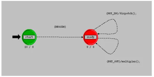
The basic model behavior, showed in Fig 10, is to exchange three kinds of message to make the ONU in the sleep mode or active mode: REQUEST, ACK and CONFIRMATION.
The OLT sends a REQUEST message to the ONU to set it to sleep for a period T. The ACK message is the reply of the ONU to the REQUEST message and the CONFIRMATION message is sent from the ONU after the sleep period to check the presence of downstream traffic and to inform the OLT of his awake status.
3.3 - Interarrival-based algorithm
The sleep period T, in this approach, is invariable and can assume only two values, Ts and 0, to decide the mode that the ONU have to trigger.
The decision is taken at the OLT, based on the inter-arrival time of the frames that it receives. The downstream traffic is instantly monitored in every arrival frame by the OLT and the inter-arrival time is calculated in average by using an exponential smoothing calculation:
i
a , k=
r⋅i
k −1+ (
1−r)⋅i
a , k −1 (1)The average downstream frame interval ia,k was utilized in place of the
instantaneous downstream frame interval, ik, where subscript k denotes the value
at time k. The value r denotes the smoothing factor and it's comprised between 0 and 1, (0<r<1). The subscript k−1 denote the value at time k–1. ia,k is updated to
every frame arrival.
Comparing the average inter-arrival time with a threshold, the OLT can predict the behavior of the downstream traffic. The first step of the algorithm is the transmission of the first frame received to the OLT, while the ONUs are in the active mode. The SPW is activated and the OLT sends a REQUEST with T set to Ts if
the average inter-arrival time is more than the threshold, otherwise, if the average inter-arrival time is less than the threshold and SPW is not activated yet, nothing changes and the frames in downstream direction are sent, or else, if the mechanism is already enable, a REQUEST with T set to zero and the downstream
traffic are sent and the ONUs remain in active mode until the reception of a new REQUEST.
When the ONU receives a REQUEST, it replies with an ACK to the OLT and, if T is equal to zero, remains in active mode, otherwise it switches to the sleep mode and its transceiver is powered off for the time Ts. When the
time expires, the specific ONU enters in active mode and sends a CONFIRMATION to the OLT after an overhead time TOH that reflect the
time which the ONU needs to wake up. At this time, the OLT controller takes not only the frame interval but
Fig.11 - SPW operation with interarrival algorithm
also the queue length into account in determining when the ONU should enter the sleep mode. This is because the OLT has to send the frames buffered in the queue during the
sleep period Ts to the ONU as a matter of first priority. This means that the ONU
does not perform SPW operation again until the downstream queue length in the OLT becomes zero.
After frame transfer is completed, in the absence of additional downstream traffic for the ONU, the OLT sends a REQUEST message including sleep period Ts to the ONU. On the other hand, in the presence of downstream traffic for the ONU, the OLT sends another REQUEST message whose sleep period is set to zero in order to keep the ONU active and forwards the downstream traffic. The REQUEST message is also used to acknowledge the CONFIRMATION message.
This process explained is the standard operation in case of the upstream traffic is absent. Indeed, if one ONU receives frames to send in upstream, can reject the
sleep mode. This happen when a REQUEST message arrives with T set to Ts . In this case, the ONU doesn't reply with an ACK but with a NACK, which means that the unit remains in active mode and it's ready to send upstream traffic.
Moreover, also in absence of upstream traffic, the ONU performs the transmission of its frames, DATA and SPW's control, by dynamic bandwidth allocation (DBA) managed in the OLT.
3.4 - Service-based algorithm
The concept of a service-based variable sleep period has been proposed in [22] to save energy in Optical Network Units (ONUs) while avoiding service degradation in the presence of traffic with demanding requirements (e.g., delay). According to this approach, each class of service (CoS) is assigned a specific sleep period. If multiple CoS are received at one ONU, the sleep period of the most demanding class is selected. The feasibility of using the concept of cyclic sleep with adaptable sleep length has also been experimentally proven in [23]. In this work, two methods of estimating packet inter-arrival time are combined with two strategies for choosing the length of the sleep period as a function of the estimated inter-arrival time. As a result, the authors in [23] present four methods for choosing the most suitable sleep period for a certain predicted value of inter-arrival time.
Usually one CoS is characterized by strict and absolute Quality of Service (QoS) constraints that must be met by the service provider to adhere to the Service Level Agreement (SLA) stipulated for users residing at the ONU. In addition, users (i.e., ONUs) may dynamically modify their service subscriptions (e.g., request a video streaming to watch a movie for some hours), possibly changing the overall delay requirements.
Utilizing the service-based variable sleep period concept, this paper proposes a method for maximizing the energy savings for ONUs while guaranteeing the
required maximum tolerable delay for different services. The approach differs from the one proposed in [22] because the chosen sleep period is a function of the maximum allowed delays rather than based on the estimated average inter-arrival time and the highest-priority class. Moreover, it differs from the approach proposed in [22] and [23] because the sleep time is a function of the CoS absolute delay constraints instead of the estimated packet inter-arrival time.
We assume that the Optical Line Terminal (OLT) is constantly aware of the services subscribed by each ONU. In addition, the OLT has a table in which services are categorized in terms of CoS with specific absolute bandwidths (i.e., data rates) and delay constraints. Such constraints can be derived from ITU-T standards such as [24,25] and statically loaded into the OLT. Leveraging on such information, the OLT dynamically builds a table containing the minimum bandwidth and maximum delay requirement per each registered ONU. The minimum bandwidth is the sum of all the minimum bandwidths (in this work, Poisson arrival process is assumed) while the maximum delay is the minimum of all the maximum acceptable delays required by the services to which the ONU is subscribed.
Tab. III shows several typical applications with their corresponding delay requirements and data rates. Note that the delays shown in this table are the strict delay requirement for the access segment only that can be inferred from contributing portion of access network to overall end-to-end delay of an Internet application presented in [25].
Service Class Service Type Maximum Delay [ms] Data Rate Bi [b/s]
1 Web Browsing 220 30.5K
2 Internet Relay Chat 110 1K
3 Multimedia on Web 84 28.8-500K
4 Voice over IP 56 5.3-64K
Tab. III - Applications with their corresponding delay requirements, data rates and service class
(SPW) (i.e., cyclic sleep) [20] whose behavior is depicted in Fig. 12. The main difference from SPW of the interarrival-based approach is that no threshold for the frame inter-arrival time is used to set the ONU sleep time. One period of activity Ta
of the ONU used for exchanging Confirmation, Request, and ACK messages with the OLT is always followed by sleep period of duration Tsl. Moreover, whenever the
OLT receives a Confirmation message from the ONU, it sends all data frames received before the Confirmation reception (e.g., frames n-2, n-1, and n in Fig.12) to the ONU. This operation requires a variable time TDS.
Fig.12 - SPW operation wiith the service-based algorithm
A first approximated model of the system OLT-ONU with the modified SPW is a M/G/1 queue with vacations [27]. The average waiting time of a frame in the queue is expressed by:
W
q , MG1=
λ⋅S
2
2⋅(1− λ⋅S )
+
V
22⋅V
(2)where S is the average service time, S2 is the second moment of the service time,
λ is the average frame arrival rate, V2 is the second moment of the vacation time
and V is the average vacation time.
A more detailed model that has been considered is a polling system with gated service policy with identical stations [26]. The average waiting time of a frame in the queue Wq,poll is expressed by:
W
q, poll=
V
2−
V
22⋅V
+
N⋅V⋅(1+λ⋅S)
2⋅(1− N⋅λ⋅S)
+
N⋅λ⋅S
22⋅(1−N⋅λ⋅S)
(3)where N is the number of ONUs. Assuming negligible processing time Tp at both
ONU and OLT and transmission time of the control frames, the vacation can be written V =Tsl+TOH+RTT , where TOH is the clock and frame synchronization
overhead and RTT is round trip time. For networks in which the service time is significantly smaller than the sleep time and λ⋅S ≪1 , Eq. (3) can be approximated as:
W
q, poll≈
N⋅V
2
(4)For example, in a scenario with 1250 byte frames, transmission rate of 10Gb/s, frame arrival rate λ = 62.5 frame/s (i.e., 625 kb/s), Tsl = 1 ms, TOH = 2 ms,
N = 1, and RTT = 0.4 ms the three contributions to Wq,poll in Eq. (3) are 0,
W
q, poll≈
V
2
=
T
sl+
T
OH+
RTT
2
(5)Solving the equation (3) and considering only one station (N = 1), (3) can be written:
W
q, poll=
W
q , MG1+
V⋅λ⋅S
1− λ⋅S
(6)The average queuing delay of the two systems can be approximately the same only if λ⋅S ≪1 and S ≪Tsl with V constant. Then:
W
q, poll≈
W
q , MG1 (7)Fig. 13 shows the algorithm for OLT to determine sleep period for an ONU. The algorithm is based on substituting Wq,poll with the maximum delay Dmax and
deriving Tsl as a function of the other quantities in Eq. (5).
Fig.13 - Algorithm for the service-based method
The algorithm starts with the service subscription of each ONU. The OLT builds or updates the table for each ONU in which the service subscribed are categorized in
terms of CoS with specific absolute bandwidths and constraint delay. Thus the maximum delay Dmax of a service composition is calculated from the table and
used in input to derive Tsl . The last step is to inform the ONU about the sleep
4 - RESULTS
4.1 – Scenario
We built a model in OPNET Modeler, a network modeling and simulator tool, to reproduce the Ethernet Passive Optical Network (EPON) architecture and to evaluate different energy saving techniques, in particular using sleep cycles for Optical Network Units (ONU).
OPNET has a hierarchical architecture, in a manner that emulates real network systems. Specialized editors address issues at different levels of the hierarchy. This provides an intuitive modeling environment and also permits re-use of lower level models.
The bidirectional transmissions in a EPON are performed by a point-to-multipoint (P2MP) network between a unit called Optical Line Terminal (OLT) placed in the Central Office (CO) and one Optical Network Unit (ONU) interfaced to the client network.
A single fiber is used to serve multiple premises, exploiting passive components, like optical splitters, by a bus topology with 1x2 optical tap couplers to attach the nodes to the bus as follow in the Fig. 14.
Fig.14 - Bus topology of the TDM-PON model
The bus topology is chosen to simplify our model. The bidirectional communication is the same as a tree topology with a passive splitter following the same policy in which the ONUs can transmit frames only to the OLT sharing the optical fiber and the OLT sends traffic in broadcast to all the ONUs using LLID. The policy is obtained in the simulator by a pipeline “closure stage” forbidding the
communication between ONUs and the Dynamic Bandwidth Allocation (DBA) algorithm to schedule the upstream traffic of each unit.
We set the distance between the OLT and the ONU in terms of propagation delay Tpr to 0.2 ms.
Since we are studying a 10G-EPON, the transmission capacity of the bus link and the optical tap couplers is set to 10 Giga bit/s.
The traffic flows downstream (from the network to users) and upstream (from the users to the network) using two different wavelengths. All the upstream signals can operate in the same wavelength in a Time Division Multiple Access (TDMA) managed by the Multi-Point Control Protocol (MPCP) assigning to the ONUs the transmission windows. There is no frame loss, since all downstream frames coming when the ONU could not receive them were buffered at the OLT .
For sake of simplicity, only downstream traffic from one OLT to one ONU is considered in simulation.
In the SPW technique, the ONU can switch between the active mode and sleep mode. Depending on which mode is enabled, the unit consume different power, in particular, Pa equal to 10 W in active mode and Ps equal to 1 W in sleep mode.
The time that the ONU needs to trigger the active mode from the sleep mode is TOH that is set to 2 ms.
Other parameters and algorithms are specific for approach.
4.2 - Interarrival-based approach
In the interarrival-based approach, we assume that the frames are generated with arrival rate following Poisson distribution and constant size, set to 1250 Byte. The maximum downstream bandwidth for each ONU running the 10G downlink is set to 1 Gb/ s.
arrival time calculated to every arrival frame. The OLT compare the average inter-arrival time with a threshold ith. We run three sets of simulation changing the
value of the threshold: 10 ms, 20 ms and 40 ms.
For this approach the sleep period Ts is only one and set to 10 ms.
We studied the average power consumption at the ONU and the average queuing delay of our model fixing the average downstream bandwidth. The results,shown in the Fig. 15,16 , were collected inserting in input the average inter-arrival time of the frames. The set of inter-arrival time is: [1 0.5 0.2 0.13 0.1 0.077 0.067 0.059 0.05 0.04 0.03 0.02 0.015 0.01 8.33e-3 6.67e-3 5.88e-3 5e-3 2.5e-3 1.67e-3 1e-3 1e-4] second. The choice to use these values reside to have more contributions on the trend of the curves and less in the portion in which the curves reach the stationary.
The average power is calculated by
P
ab=
T
a⋅
P
a+
T
s⋅
P
sT
a+
T
s (8)The time Ta is the duration of the ONU in active time. In absence of downstream
traffic, it is the sum of the overhead time, TOH, and the round-trip transmission
delay between the OLT and ONU, equal to 2⋅Tpr . Otherwise the active time is variable and equal to 2⋅Tpr+TDS , where TDS is the time to send the frames in
queue arrived during the previous sleep period.
The objective to implement this approach is to compare the results of our simulations with the ones showed in the paper [20]. As shown in the Fig. 15 and Fig. 16 the results obtained are very close with the same increasing trend. The theoretical average power for low bandwidth was reached as no downstream traffic was presented and the SPW was activated for all the simulation time. Indeed for a value of 0.01 Mb/s, the average power is 2.74 W.
(a) (b)
Fig.15 - Comparison between the average power simulation results (a) and the published results (b)
On the other hand the maximum average power was reached for high bandwidth because the ONU was continuously awake. Between 1 Mb/s and 10 Mb/s in both the results the average power is 10 W the same value of power in which the ONU is in active mode.
(a) (b)
Differently from [20] the maximum average delay was around 6.2 ms instead of 5 ms because the transition time from the sleep to the awake state as well as the RTT of the exchange messages were considered in the calculation of queuing delay. The same motivation applies to the lowest average delay.
4.3 - Service-based approach
In the scenario where the service-based approach is applied the data frames arrive at the OLT according to a Poisson process with arrival rate λ frames/s depending on the ONU service composition. We run two sets of simulation, in the first set only one source is used to generate traffic with the bandwidth of a service composition and in the second a source generates traffic for each service composition.
In both the sets, the simulations are run twice with different frame size fs , one is
constant and equal to 1250 bytes, the second one is uniformly distributed between 72 and 1526 bytes, respectively the Ethernet minimum and maximum frame size.
Without loss of generality, this paper limits the number of traffic classes to 4 and considers several class combinations as shown in the left part of Tab. IV. For classes with a range of data rates, the maximum one has been considered to compute λ. The values of λ-1 reported in Tab. IV have been computed by following
formula:
λ
−1=
8f
s∑
i∈ SB
i (9)where S is the service composition.
services that are part of it, assuming frames arrive following a Poisson process. The evaluated performance metrics are the frame queuing delay D and the energy efficiency η. Here, the efficiency is defined as
η = 1− Esleep
Enosleep
(10)
where Esleep is the energy consumed by the ONU implementing the proposed sleep
mode and Enosleep is the energy consumed by the ONU if it is always active.
The results are collected by post processing operations setting in input the Tsl and
the average inter-arrival time values in input to the simulator for a specific service composition. The Tsl is calculated as
Tsl = 2*Dmax - TOH - RTT
where Dmax is the maximum constraint delay of a service composition taken from
the table that the OLT built per each registered ONU; TOH is the time of overhead
in which the ONU switches from the sleep mode to active mode; RTT is the round-trip time between OLT and ONU.
The inter-arrival time is calculated as in (9)
The output parameters of the system are the queuing delay for the frames with constant and uniform distributed size and the energy efficiency calculated as in (10). Moreover the confidence interval with confidence level of 0.9 is calculated for both output parameters.
The results about the first set of simulation are shown in the Tab. IV. In the right part of the table is indicated that in any service composition, ONU can save up to around 89% of energy while not violating any delay requirements. The advantage comes from the method of determining the sleep time that allows the ONU to maximize the sleep time, thus maximizing the energy savings, without violating the service delay constraints.
Input Parameters Output Parameters Service Composition λ−1 [ms/frame] Dmax [ms] Tsl [ms] Dconstant [ms] Duniform [ms] Efficiency η [%] Conf. Interval Dconstant , Duniform (conf.lev. 0.9) [ms] Conf. Interval η (conf.lev. 0.9) 1+2+3+4 17 56 109 55.7 55.7 88.01 ± 1.8⋅10−1 ± 3.0⋅10−4 1+2 317 110 217 109.7 109.7 89.01 ± 3.7⋅10−1 ± 1.3⋅10−4 2+3 20 84 165 83.7 83.7 88.66 ± 0.7⋅10−1 ± 3.2⋅10−4 4 156 56 109 55.7 55.7 88.05 ± 5.4⋅10−1 ± 1.9⋅10−4
Table IV – Results per service composition with one generator of traffic
The reliability of the formula used for this system is compared with our simulations. The results are taken with a Tsl set and changing the average
bandwidth of the traffic generated:
B =
10
2
xGbit / s
(11)with x = {0, 1, 2, 3, 4, 5, 6}.
The average inter-arrival time is calculated as in (9).
How the Fig. 17 shows, the curves of the theoretical average delay and the simulated average delay are exactly the same until going close to the limit of transmission rate of 10Gb/s.
The last step is to verify that the results collected about the average delay D, considering only one generator, are the same considering one generator per service with the own arrival rate.
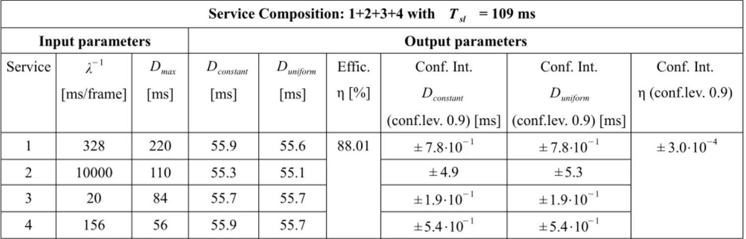
The second set of simulation is launched to verify that the simplification to use only one generator with the bandwidth of a service composition was correct and if the service with the maximum constraint still respect the acceptable delay. The results are shown in the Tables V, VI, VII.
Service Composition: 1+2+3+4 with Tsl = 109 ms
Input parameters Output parameters
Service λ−1 [ms/frame] Dmax [ms] Dconstant [ms] Duniform [ms] Effic. η [%] Conf. Int. Dconstant (conf.lev. 0.9) [ms] Conf. Int. Duniform (conf.lev. 0.9) [ms] Conf. Int. η (conf.lev. 0.9) 1 328 220 55.9 55.6 88.01 ± 7.8⋅10−1 ± 7.8⋅10−1 ± 3.0⋅10−4 2 10000 110 55.3 55.1 ± 4.9 ± 5.3 3 20 84 55.7 55.7 ± 1.9⋅10−1 ± 1.9⋅10−1 4 156 56 55.9 55.7 ± 5.4⋅10−1 ± 5.4⋅10−1
Table V - Results for a service composition 1+2+3+4 with a generator of traffic per service
Service Composition: 1+2 with Tsl = 217 ms
Input parameters Output parameters
Service λ−1 [ms/frame] Dmax [ms] Dconstant [ms] Duniform [ms] Effic. η [%] Conf. Int. Dconstant (conf.lev. 0.9) [ms] Conf. Int. Duniform (conf.lev. 0.9) [ms] Conf. Int. η (conf.lev. 0.9) 1 328 220 109.7 109.7 89.01 ± 3.8⋅10−1 ± 3.8⋅10−1 ± 1.3⋅10−4 2 10000 110 109.7 109.6 ± 2.1 ± 2.1

![Table I - Power consumption [W] of 10G-EPON ONU (1GE, 2POTS, 1 M O CA)](https://thumb-eu.123doks.com/thumbv2/123dokorg/7534033.107386/20.918.86.840.337.536/table-power-consumption-epon-onu-ge-pots-ca.webp)