SCUOLA DOTTORALE DI INGEGNERIA SEZIONE DI
INGEGNERIA DELL’ELETTRONICA BIOMEDICA,
DELL’ELETTROMAGNETISMO E DELLE
TELECOMUNICAZIONI
XXIII CICLO
Progetto di Metamateriali per Applicazioni alle Telecomunicazioni
Luca Scorrano
A.A. 2010/2011
Docente Guida: Prof. Lucio Vegni
Tutor: Prof. Filiberto Bilotti
__________________________________________________________________________
Luca Scorrano: Progetto di Metamateriali per Applicazioni alle Telecomunicazioni 2
__________________________________________________________________________
Luca Scorrano: Progetto di Metamateriali per Applicazioni alle Telecomunicazioni 3
I
NDEXSOMMARIO ... 4
1. INTRODUCTION ... 6
1.1 BRIEF STORY OF METAMATERIALS ... 7
2. BASIS OF METAMATERIAL THEORY ...10
2.1 NEGATIVE PERMITTIVITY AND PERMEABILITY ... 10
2.2 TRANSMISSION LINE MODEL OF METAMATERIALS... 13
2.2.1 TEM(z) case ...14
2.2.2 Reflection coefficient for two homogeneous isotropic indefinite dielectric slab in free space ...16
2.2.3 TM(z) case ...17
2.2.4 TE(z) case ...19
2.2.5 Equivalent TL model for DNG and SNG media...20
2.3 ANALYSIS AND HOMOGENIZATION OF COMPOSITE MEDIA ... 22
2.4 VOLUME METAMATERIALS VS PLANAR METAMATERIALS ... 24
3. METAMATERIAL-BASED AND METAMATERIAL INSPIRED DEVICES ...27
3.1 METAMATERIAL SLABS WITH EXTREME VALUES OF THE CONSTITUTIVE PARAMETERS .... 28
3.1.1 TEM(z) polarization ...29
3.1.2 TE(z) polarization ...31
3.1.3 TM(z) polarization ...33
3.2 EPSILON NEAR ZERO REFLECTORS AT THZ ... 36
3.3 NEAR FIELD PATTERN SYNTHESIS TROUGH NANO-CIRCUIT SURFACES ... 38
3.4 ENHANCED TRANSMISSION THROUGH SPLIT RING RESONATORS AND OTHER KINDS OF SMALL RESONATORS ... 48
3.4.1 Power transmission through electrically small apertures ...48
3.4.2 The double SNG cover ...49
3.4.3 The single MNG cover ...55
3.4.4 Design of an inclusion-based single MNG cover layout ...56
3.5 TRANSMISSION ENHANCEMENT,IMPEDANCE MATCHING AND MODAL CONVERSION THROUGH SINGLE RESONATING OMEGA PARTICLES, ... 60
3.6 FREQUENCY SELECTIVE SURFACES AS METAMATERIALS REPLACEMENT ... 66
3.7 MAGNETISM AT THZ SCALE AND APPLICATIONS ... 78
3.7.1 Plasmonic nano-pillar couples ...78
3.7.2 Silver nano-spheres rings ...83
4. CONCLUSIONS ...91
BIBLIOGRAPHY ...92
PUBLICATIONS ...100
__________________________________________________________________________
Luca Scorrano: Progetto di Metamateriali per Applicazioni alle Telecomunicazioni 4
S
OMMARIONel presente lavoro sono descritti i risultati ottenuti nel corso del triennio della scuola dottorale relativamente al progetto di Metamateriali per applicazioni alle telecomunicazioni. Vengono inizialmente approfondite le tematiche relative alla caratterizzazione di tali mezzi complessi e le problematiche relative al progetto di strutture fisicamente realizzabili su di essi basate. Poiché un Metamateriale non è altro che un mezzo realizzato tramite inclusioni dielettriche o metalliche inserite in un mezzo ospite, quando si passa da una rappresentazione in termini di uno strato ideale lineare isotropo ed omogeneo al suo modello reale devono essere tenute in seria considerazione le caratteristiche elettriche dei mezzi conduttori e dielettrici coinvolti nel progetto, l’anisotropia delle inclusioni, la possibilità di poter omogeneizzare la struttura per poterne fornire una descrizione in termini di parametri macroscopici e l’effettiva capacità della struttura reale di supportare fenomeni di interfaccia, caratteristica invece strettamente legata al comportamento microscopico del Metamateriale. Questi ultimi due aspetti sono in realtà quelli che presentano le maggiori criticità essendo generalmente tali inclusioni più piccole della lunghezza d’onda di interesse ma non molto più piccole (tipicamente nell’ordine di un decimo della lunghezza d’onda). Viene poi fornito un equivalente a linee di trasmissione per uno strato lineare isotropo ed omogeneo di un Metamateriale al fine di poter definire, in termini di valori limite della permeabilità magnetica e della permittività elettrica, le caratteristiche di un mezzo ideale che possa emulare il comportamento una parete magnetica perfetta. Se ne suggeriscono due possibili implementazioni alle microonde, tramite l’uso di Split-Ring Resonators (SRR), ed alle frequenze ottiche tramite multistrati metallo-dielettrici realizzati tramite un’alternanza di argento e silice. Sono poi approfondite le problematiche relative al fenomeno della trasmissione straordinaria e vengono proposte una serie di metodologie basate sull’eccitazione di risonanze magnetiche localizzate al fine di incrementare la potenza trasmessa da una apertura elettricamente piccola. Vengono proposti degli approcci alle microonde basati sull’impiego di SRR e di inclusioni Omega, ed alle frequenze ottiche, basati invece sull’uso di nano-particelle realizzate con metalli nobili. L’utilizzo di strutture diverse nei due casi, in termini di
__________________________________________________________________________
Luca Scorrano: Progetto di Metamateriali per Applicazioni alle Telecomunicazioni 5
geometrie e materiali, è dettata dalla saturazione della risposta elettromagnetica delle inclusioni metalliche tipicamente usate alle microonde. In particolare, un aspetto significativo dei dispositivi presentati, avente come fine quello di aumentarne gli ambiti applicativi, è l’elevata miniaturizzazione di questi stessi. Viene poi suggerita, alle frequenze ottiche, la possibilità di sintetizzare in campo vicino una distribuzione di campo arbitraria, avente dettagli più piccoli della lunghezza d’onda, come diretta applicazione della teoria dei nano-circuiti ottici, mediante celle dielettriche che realizzano opportuni valori campionati di impedenza superficiale di un apposito schermo focalizzatore. Sono poi esplorate le possibili alternative, in alcuni ambiti applicativi, all’uso di Metamateriali, e vengono individuate a tal fine le superfici selettive in frequenza come validi candidati. Viene suggerita, a titolo di esempio, una possibile applicazione dell’uso di tali superfici al fenomeno della trasmissione straordinaria. I limiti e le effettive potenzialità dei Metamateriali sono infine analizzate.
__________________________________________________________________________
Luca Scorrano: Progetto di Metamateriali per Applicazioni alle Telecomunicazioni 6
1. I
NTRODUCTIONThe evolution of technology and the scientific progress have been relying all long on two complementary processes, apparently at odds with each other, but proving that intrinsic strong connection existing between pure and applied research.
On a hand, we recognize the usage of consolidate concepts in unusual fields of application, the rediscovery from a completely new perspective, we would say, of ancient or lost concepts buried long time in the graveyard of inventions that have already proven their utility.
On the other hand, we look, not infrequently with suspicion, at the proposal of completely new theories and intuitions undermining the current understanding of the world around us, although hard to be verified experimentally due to intrinsic technological limitations. The dualism of the aforementioned processes is, in a way, the same dualism that is found, for instance, in the contrast between quantum theory and determinism, dualism that is solved by the universal necessity of the whole mankind to give actual answers to both intellectual and practical needs.
From this perspective, the theory of metamaterials is exposed in the present work and many electromagnetic devices are presented both as straight applications of the aforementioned concept and as application of the metamaterial-point-of view to the needs and the requirements that such devices try to cope with.
__________________________________________________________________________
Luca Scorrano: Progetto di Metamateriali per Applicazioni alle Telecomunicazioni 7
1.1 BRIEF STORY OF METAMATERIALS
Victor Veselago, in a paper dated 1968 [1], was one of the first, at the author’s best knowledge, to study the interaction between electromagnetic waves and media characterized by negative values of both the electric permittivity and the magnetic permeability . One of the main consequences that was found is that the wave-vector k, representing the phase velocity of a wave, turned out to be anti-parallel to the Poynting vector S, representing instead the power-flow associated to the wave. This was the reason why Veselago called such media “left-handed”; nowadays an interpretation based on the concept of negative index of refraction is preferred. This fact can be immediately derived from Maxwell’s equations, written in the case of a monochromatic plane wave for a homogenous isotropic medium, where each term results proportional to ejk rt:
j j j j E H k E H H E k H E (1.1)
From (1.1) if >0 and >0 (a Double PoSitive media or DPS), the electric field E and the magnetic field H are right-handed, otherwise, if <0 and <0 (a Double NeGative media or DNG), they form a left-handed triplet.
The other relevant feature of DNG media, as it was previously mentioned, is to show a negative index of refraction. From Maxwell’s equations it is straightforwardly derived:
2 2 2 2 2 2 z, t z, t t z, t z, t t E E H H (1.2)Each of (1.2) can be decomposed in three scalar equations admitting solutions
exp[ j n k d t ] . The complex quantities and appear in the wave equation as product. Apparently it seems it does not exist any difference between DNG and DPS media. Solutions for (1.2) are propagating waves both in case of >0 and >0 and <0 and <0. In order to resolve the ambiguity introduced by de definition of index of refraction n if <0 and <0 the notation =||exp(i) and =||exp(i) can be introduced.
__________________________________________________________________________
Luca Scorrano: Progetto di Metamateriali per Applicazioni alle Telecomunicazioni 8
Moreover, to ensure the passivity, the imaginary part of the square root must be negative. Veselago postulated that radiation coming from a point source on one side of a DNG slab could be focused on the other side, suggesting this way the possibility to achieve flat lenses.
Figure 1 Veselago’s materials classification. He was not able to find a natural or artificial structure exhibiting ε<0 and μ<0 at the same time, but he suggested the use of plasmas and ferrites as single-negative metamaterial replacements in proper frequency ranges. (Pictures from ref. 1)
Media exhibiting <0 or <0 are not easily found in nature, consequently there was no way out of Veselago intuition until 1990s. In 1996, 1998 and 1999 J. B. Pendry published a series of papers were structures exhibiting negative values of electric permittivity and of magnetic permeability were shown [2,3,4]. Such materials were obtained through periodic structures with both base elements and spacing smaller than the working wavelength: from a heuristic point of view, the wave “sees” such a composite medium as an homogeneous medium. This initial process of launching the subject of Metamaterials was then completed
__________________________________________________________________________
Luca Scorrano: Progetto di Metamateriali per Applicazioni alle Telecomunicazioni 9
with the seminal papers of Smith [5], Shelby [6] and Pendry [7]. The first demonstrated experimentally that an electromagnetic wave cannot propagate in medium in which only or is negative (i.e. a Single NeGative medium, SNG) but propagation is restored when they are both, the second verified a negative index of refraction designing a DNG prism at 10.5 GHz, the latter provided the first practical application, postulating not the possibility of beating the classic diffraction limit but the possibility of perfect imaging, that means the possibility of reproducing both the travelling waves and all the evanescent waves associated with the object. The initial stage of this process could then be considered as completed.
In accordance with the commonly used definition, metamaterials are artificial materials
made of dielectric or metallic inclusion embedded in a host medium, whose spacing and size are smaller than the working wavelength, exhibiting properties which are not commonly available in nature. The electromagnetic behavior of these engineered materials relies both on chemical and structural properties of their composition, using properly designed inhomogeneities to synthesize a required macroscopic behavior.
__________________________________________________________________________
Luca Scorrano: Progetto di Metamateriali per Applicazioni alle Telecomunicazioni 10
2. B
ASIS OFM
ETAMATERIALT
HEORYIn this chapter the basis of the theory of metamaterial are briefly illustrated. In the first section, Drude and Drude-Lorenz models are recalled. Assuming that the concept of DNG or SNG material is always related to specific frequency bands and that real-life structures usually exhibit a much more complex behavior, a usual practice in order to describe real materials and electromagnetic mixtures is to linearly combine those models, providing proper values of the characteristic parameters for each tem of the sum, in order to fit experimental data. Transmission Line (TL) equivalent models of DPS, DNG and SNG media are then given. Finally the problems related to the homogenization of complex materials and the concept of Metamaterial Inspired Device (MID) are exposed, and a classification of Metamaterials in 2D Metamaterials and 3D Metamaterials is presented.
2.1 NEGATIVE PERMITTIVITY AND PERMEABILITY
Let us recall the differential equation describing the effect of an electric field E applied to those electrons that, in a metal, are free to move and collide each other [8]:
d e
dt m *
v v
E (2.1)
where v is the electron velocity, m* the effective mass and τ is the average time between two collisions, also known as relaxation time, the term 1/ is instead known as damping factor. The current density can be then be written as follows:
Ne
J v (2.2)
where N is the conduction electrons density, giving:
2 2 0 p Ne d dt m * J J E E (2.3)
__________________________________________________________________________
Luca Scorrano: Progetto di Metamateriali per Applicazioni alle Telecomunicazioni 11
2 p 0 N e m * (2.4)
is known as plasma frequency, i.e. the characteristic frequency of the electronic cloud oscillation as response to a mechanical or electric stimulus, also known as plasmon. For rapidly oscillating fields:
j t j t e e d j dt 0 0 E E J J J J , J
E (2.5)where σ is the conductivity, solving for
we have:
2 0 p 1 j (2.6)From (2.6) it can be noted that at low frequencies
is proportional to τ, consequently, the less are the collisions the highest is the velocity, resulting almost real and independent of frequency. The lattice dielectric constant can be found from Maxwell’s equations:
0 0 j 1 j H E (2.7)The term in square brackets is the definition of relative permittivity, finally:
2 0 p 2 2 p p 0 0 0 2 0 1 j 1 1 j 1 j j ( ) (2.8)A metamaterial whose behavior is consistent with the Drude model can be then obtained by using, for instance, the conductive thin wires array of Figure 2.
__________________________________________________________________________
Luca Scorrano: Progetto di Metamateriali per Applicazioni alle Telecomunicazioni 12
Figure 2 Basic cell of a wire medium exhibiting a Drude-like dispersion of the electric permittivity.
In case wires are not continuous but are cut-wires the Drude model is replaced with the Drude-Lorenz model:
2 2 p 0 0 2 2 0 1 j ( ) (2.9)where 0 is the resonance frequency; and <0 in the band ω0<ω<ωp.
The wire medium has been historically studied in the field of radar technology applications, particularly in the design of high permittivity low loss materials by Brown [9] (see also the comprehensive survey by Collin in [10]), and in simulation of plasmas by Rotman [11]. The same phenomena and applications were rediscovered fifty years later by Pendry, Smith and Shelby, all of them inspired by [9,11].
The way to obtain negative values of the magnetic permeability is similar and relies on arrangements of inclusions of different shape, exhibiting a magnetic behavior, as, for instance, Split Ring Resonators (SRRs). Veselago suggested instead the use of anisotropic gyroscopic substances in which the effective permeability can be negative for one of the two circular polarizations. Moreover, the possibility to achieve negative permeability was
__________________________________________________________________________
Luca Scorrano: Progetto di Metamateriali per Applicazioni alle Telecomunicazioni 13
already demonstrated ten years earlier by Thompson [12,13], and again, different experiments led to the same results in the work of Marques [14].
Figure 3 Basic cell of a SRR medium exhibiting a Lorenz dispersion of the magnetic permeability.
In such case Drude-Lorenz model describing this structure is the following:
0 2 2 0 F 1 j ( ) (2.10)where F is a parameter related to the shape of the structure. A more detailed analysis of this kind of structures is given in [15].
2.2 TRANSMISSION LINE MODEL OF METAMATERIALS
In this section the transmission line model for linear homogenous isotropic media is recalled and specialized in case of metamaterial slabs, deriving a circuital equivalence between DPS,DNG,SNG and distributed constants transmission lines.
__________________________________________________________________________
Luca Scorrano: Progetto di Metamateriali per Applicazioni alle Telecomunicazioni 14
Let us recall the expressions of the curl of E and H, for a linear homogenous isotropic media in the frequency domain, given a monochromatic excitation in the form ej t :
j j E H H E (2.11) 2.2.1 TEM(z) case
Through an arbitrary orientation of the coordinate axis, in the TEM case, it can be always verified Ez=Hz=0 and Ey=Hx=0: x y x y x y E j H z E 0 y H j E z H 0 x
A B C D (2.12)From (2.12) it is straightforwardly obtained:
2 y 2 y 2 2 2 x x 2 H H 0 z E E 0 z (2.13)
From the positions V(z)=Ex(z), I(z)=Hy(z), ZTEM j and YTEM j (2.13) can be written in the characteristic form:
x TEM y y TEM x H Y E z E Z H z (2.14)
Called the Telegraphers’ Equations, YTEM and ZTEM are the admittance and the impedance per unit length, functions of the spatial variable z, whose dimensions are respectively
__________________________________________________________________________
Luca Scorrano: Progetto di Metamateriali per Applicazioni alle Telecomunicazioni 15 [Siemens/m] and [Ohm/m]. If the medium is lossless:
j z j z x 0 0 j z j z y 0 0 E z E e E e H z H e H e (2.15)That can be rewritten as follows:
j z j z x 0 0 j z j z y 0 0 00 TEM TEM TEM TEM
E z E e E e 1 H z E e E e Z Z Z / j Z / Z Y (2.16)
where Z0 is the characteristic impedance of the medium (or of the line according to the formalism used): TEM 0 TEM R j L Z j Z G j C Y j (2.17)
Moreover, given E z
E e0 j z, H z
H e0 j z, E z
E e 0 j z and
j z0
H z H e
(2.16) may be rewritten as follows:
x y 0 E z E z E z 1 H z E z E z Z (2.18)We now define two functions, the line impedance Z(z) and the reflection coefficient R(z):
jz jz x 0 0 0 jz jz y 0 0 E z E e E e Z z Z H z E e E e (2.19)
0 2 jz 0 E z E R z e E z E (2.20)Those quantities are found to be mutually dependent:
0 1 R z Z z Z 1 R z (2.21)__________________________________________________________________________
Luca Scorrano: Progetto di Metamateriali per Applicazioni alle Telecomunicazioni 16
0 0 Z z Z R z Z z Z (2.22)2.2.2 Reflection coefficient for two homogeneous isotropic indefinite dielectric slab in free space
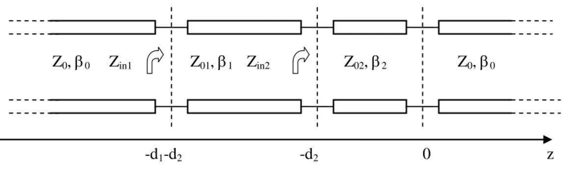
Before analyzing the TE(z) and the TM(z) a useful result is derived in case of two paired homogeneous dielectric slabs, such result will be recalled in Chapter 3 when studying the properties of a conjugate matched pair of SNG slabs. Let us consider four transmission lines connected in series with characteristic impedance Z0, Z01, Z02 and Z0 respectively, the first extending in the region z<-d1–d2, the second in -d -d <z<-d , the third in –d1 2 2 2<z<0 and the fourth in z>0.
Figure 4 Transmission line representation of a two indefinite homogeneous isotropic dielectric slabs in free space.
To evaluate the reflection coefficient at the interface z=-d1-d2 is enough to apply the definition introduced in the previous section:
0 02 2 2 in2 02 02 0 2 2 Z jZ tan d Z Z Z jZ tan d (2.23) Z0, 0 Zin2 z -d1-d2 0 Z01, 1 -d2 Zin1 Z02, 2 Z0, 0__________________________________________________________________________
Luca Scorrano: Progetto di Metamateriali per Applicazioni alle Telecomunicazioni 17
in2 01 1 1 in1 01 01 in2 1 1 0 02 2 2 02 01 1 1 02 0 2 2 01 0 02 2 2 01 02 1 1 02 0 2 2 02 0 02 2 2 01 1 1 02 0 2 2 01 01 02 0 01 Z jZ tan d Z Z Z jZ tan d Z jZ tan d Z jZ tan d Z jZ tan d Z Z jZ tan d Z jZ tan d Z jZ tan dZ Z jZ tan d jZ tan d Z jZ tan d
Z Z Z j Z Z
tan
2 2d
Z02tan
1 1d
Z0jZ02tan
2 2d
(2.24)
in1 0 in1 0 02 0 02 2 2 01 1 1 02 0 2 2 01 0 01 02 0 01 2 2 02 1 1 0 02 2 2 02 0 02 2 2 01 1 1 02 0 2 2 01 01 02 0 01 2 2 Z Z R L Z ZZ Z jZ tan d jZ tan d Z jZ tan d
Z Z
Z Z j Z Z tan d Z tan d Z jZ tan d
Z Z jZ tan d jZ tan d Z jZ tan d
Z Z Z j Z Z tan d
0 02 1 1 0 02 2 2 2 2 2 2 01 02 0 02 01 0 2 2 0 02 01 1 1 2 2 2 2 2 2 01 02 0 02 01 0 2 2 0 01 02 0 02 01 1 1 2 2 1 1 2 2 Z Z tan d Z jZ tan d Z Z Z Z Z Z Z Z Z j tan d tan d Z Z Z Z Z Z 2Z Z Z Z Z Z jtan d tan d tan d tan d
(2.25) 2.2.3 TM(z) case
Assuming Hz=0 and, through an arbitrary orientation of the coordinate system, Ey=Hx=0, the following result is achieved:
__________________________________________________________________________
Luca Scorrano: Progetto di Metamateriali per Applicazioni alle Telecomunicazioni 18
x z y z 2 y x y 2 x y x y x y z E j H E z x E 0 y E 1 H j H E 0 z j x y H j E H z j E z H j E x (2.26)
For a linear isotropic source-free and homogeneous medium H satisfies,
2 y 2 x y 2 2 2 2 y 2 z 2 y y x 2 y 2 z y 2 H k H x k 0 H H 0 k H y H 0 H k H z H H (2.27) leading to: x eq y 2 x y x y 2 x eq 2 y x y x E j H E j H 1 k H z z j 1 k H j E H z j E z (2.28)
By the positions ZTM j eq and YTM j :
y TM y x TM x H Y E z E Z H z (2.29)
__________________________________________________________________________
Luca Scorrano: Progetto di Metamateriali per Applicazioni alle Telecomunicazioni 19
2 x 2 eq TM TM 0 TM k 1 Z Z Y (2.30) 2.2.4 TE(z) case
Assuming Ez=0 and, through an arbitrary orientation of the coordinate system, Hy=Ex=0, in analogy with the previous section:
y z y x y x x z 2 y y x y 2 z x E j H x E j H E z j H z H j E H E z x H 1 j E H z j x 0 y H 0 y (2.31) Again, 2 y 2 x y 2 2 2 2 y 2 z 2 y y x 2 y 2 z y 2 E k E x k 0 E E 0 k E y E 0 E k E z E E (2.32) By applying (2.32) to (2.31):
__________________________________________________________________________
Luca Scorrano: Progetto di Metamateriali per Applicazioni alle Telecomunicazioni 20
x eq y y 2 x x eq 2 2 x y x y y x H j E E z j H k z 1 H j E 1 k E z j E j H z (2.33)
Through the positions ZTE j and YTE j eq (2.33) are rewritten in the form:
x TE y y TE x H Y E z E Z H z (2.34)
The characteristic impedance is then defined as:
TE TE 0 2 eq TE x 2 Z Z Y 1 k (2.35)
2.2.5 Equivalent TL model for DNG and SNG media
From(2.35) and (2.30) the equivalent inductance per length unit Leq and the equivalent capacitance equivalent per length unit Ceq may be written:
2 TM x eq 1 eq 1 2 k L A A 1 (2.36) TM eq 2 eq 2 C A A (2.37)
in the TM case, while in the TE(z) case:
TE eq 1 eq 1 L A A (2.38) 2 TE x eq 2 eq 2 2 k C A A 1 (2.39)
__________________________________________________________________________
Luca Scorrano: Progetto di Metamateriali per Applicazioni alle Telecomunicazioni 21
where A1 and A2 are two positive terms depending on the geometry of the transmission line. Through the introduction of the terms Leq and Ceq the definition of a TL equivalent model, both for evanescent and propagating waves in DPS, DNG and SNG media, is now possible. If eq is real negative, Leq results real and negative. It can be assumed that such a negative reactance is due to an effective positive capacitance -j/Ceff = -j|Leq|= in a certain frequency range. Consequently, in the transmission line equivalent model, a negative series Leq results in a positive series Ceff. By applying the duality principle the case eq<0 is straightforwardly obtained.
The quantity kx is assumed always positive both for a wave propagating in a lossless medium (where k2x 2 ) both for an evanescent wave (where instead k2x 2 ). In Table I, symbols L-C, C-C, L-L and C-L are used to identify which reactive elements are used as series elements (first letter) and which as shunt element (second letter).
TABLE I DPS (>0, >0) DNG (<0, <0) ENG (>0, <0) MNG (<0, >0) Propagating TM wave (k2x 2 ) TM eq TM eq L >0 C >0 Z L-C TL TM eq TM eq L <0 C <0 Z C-L TL Not applicable because 2 2 x k in the case kxfor lossless ENG Not applicable because 2 2 x k in the case kx for lossless MNG Evanescent TM wave (k2x 2 ) TM eq TM eq L <0 C >0 Z C-C TL TM eq TM eq L >0 C <0 Z L-L TL TM eq TM eq L >0 C <0 Z L-L TL TM eq TM eq L <0 C >0 Z C-C TL
__________________________________________________________________________
Luca Scorrano: Progetto di Metamateriali per Applicazioni alle Telecomunicazioni 22
Propagating TE wave (k2x 2 ) TE eq TE eq L >0 C >0 Z L-C TL TE eq TE eq L <0 C <0 Z C-L TL Not applicable because 2 2 x k in the case kx for lossless ENG Not applicable because 2 2 x k in the case kx for lossless MNG Propagating TE wave (k2x 2 ) TE eq TE eq L <0 C >0 Z C-C TL TE eq TE eq L >0 C <0 Z L-L TL TE eq TE eq L >0 C <0 Z L-L TL TE eq TE eq L <0 C >0 Z C-C TL
TL equivalent model for propagating and evanescent TM and TE waves in DPS, DNG, MNG and ENG media.
2.3 ANALYSIS AND HOMOGENIZATION OF COMPOSITE MEDIA
In accordance with the definition given in Section 1.1, the electromagnetic behavior of metamaterials is usually described in terms of effective parameters, i.e. an effective permittivity and an effective permeability. In the long wavelength limit, in fact, the propagation of electromagnetic fields in complex media can be macroscopically described in terms of average fields. When analytically analyzing a complex media, the calculation of the polarizability of the single inclusion is required as starting point; the small scatterers forming the mixture can be replaced by dipole moments which average into the electric polarization.
mix eff e mix V 1 dV V D E E P f f r (2.40)being ethe environment permittivity, and Vmix a representative volume of the sample, and
mix mix f n d P p p E P (2.41)__________________________________________________________________________
Luca Scorrano: Progetto di Metamateriali per Applicazioni alle Telecomunicazioni 23
being P the average electric polarization density, pmix the dipole moment of a single inclusion, n the number density of the inclusion in Vmix , α the scalar electric polarizability, df the depolarization factor depending on the inclusion shape. Analogous consideration may be done about the effective magnetic permeability μeff.
The Clausius-Mossotti formula gives the effective electrical parameters of the mixture as function of the polarizabilities and, through the Maxwell-Garnett relation, these polarizabilities are replaced with physical material parameters of the inclusions [10,16]: The discussion by Belov and Simovski in the field of metamaterials [17] is based on similar ideas, generalizing the Clausius-Mossotti relation with the inclusion of a radiation term.
However, in practical cases, this analytical approach turns out to be unsuccessful due to the initial assumptions of this method: the expression of the polarizability of a single inclusion has to be evaluated, which is a challenging task for complex shapes; secondly, inclusions are required both to be much smaller than the operating wavelength, and weakly interacting with scatterers placed at close distance, meaning that the inter-spacing between particles has to be much greater than the particle size. In the most of the cases inclusions are small but no such small (typically λ/10) and closely packed to obtain a material with a strong engineered response, taking advantage from the same unwanted coupling. This results can be obviously generalized through the introduction of a coupling term but, in this case, a closed expression for this term is, once again, required.
What is done in practice is to retrieve the characteristic parameters of a complex material from the reflection and transmission coefficients of a sufficiently large sample, so that the retrieved parameters can be assumed as those of a bulk material. This approach can be generalized also for samples of small thickness and for moderate low frequencies at the cost of introducing two transition layers at the sides of the slab [18]. In the most of many practical cases, it is also to be taken into account the effect of the thickness of the sample, the electromagnetic response of a thin sample varies with the thickness until it is large enough that the retrieved parameters can be assumed as those of a bulk material [19]. It is also worth noticing early examples by Lewin [20] concerning the calculation of the
__________________________________________________________________________
Luca Scorrano: Progetto di Metamateriali per Applicazioni alle Telecomunicazioni 24
effective permittivity and permeability of a medium loaded with spherical particles (this method have then been successfully applied in the metamaterial context by many authors, see for instance [21,22]) and the work of Brillouin in the field of wave propagation in periodic structures. Part of this work, has been applied for describing wave propagation in periodically loaded transmission lines also known as Transmission Line Metamaterials (TL-MTM) [23-27].
2.4 VOLUME METAMATERIALS VS PLANAR METAMATERIALS
That kind of metamaterials based on magnetic resonators, wires, parallel plates, and in general on arrangements of 3D structures are commonly classified as volume metamaterials. What was found by more than one research group at the same time [23-27] was that a much more cost-effective approach to the design of metamaterials would have relied on periodically loaded standard transmission line structures. Given a classical TL representation of a differential section of a lossless guiding structure, as already seen in Section 2.2: Z Z Z L Z C
Figure 5 TL equivalent of a standard lossless guiding structure.
When loading such a structure with series capacitors and shunt inductors of proper value, provided a unit cell is smaller than the guided wavelength, in particular < λg/4 [28], so that the line is seen by the electromagnetic waves as effectively homogeneous, a composite left-handed right handed behavior is then expected:
__________________________________________________________________________
Luca Scorrano: Progetto di Metamateriali per Applicazioni alle Telecomunicazioni 25
Z Z Z 1 C Z 2 C 1 L 2 L
Figure 6 TL equivalent of a composite left-handed right-handed waveguide.
In such a case, the propagation constant, that is defined as the square root of the product between the impedance per-unit length and the admittance per-unit length, is:
1 1 2 2 2 1 1 1 1 2 2 2 2 2 1 1 k a j b Z Y j L j C C L C L 1 s L C L C C L (2.42) where
1 2 2 1 1 2 2 1 1 1 1 if min , L C L C s 1 1 1 if max , L C L C (2.43)A particular case is found when:
1 2 2 1
L C L C (2.44)
known as balance condition. In such case it can be demonstrated that the propagation constant reduces to:
1 1 2 2 1 b L C L C (2.45)
__________________________________________________________________________
Luca Scorrano: Progetto di Metamateriali per Applicazioni alle Telecomunicazioni 26
It is clear how the left-hand term is dominant al lower frequencies while, the right-hand term is dominant at higher frequencies. It is also worth noticing that in general, accordingly to (2.42) and to (2.43), the phase constant can be purely imaginary in certain frequency bands resulting in a stop-band behavior that is not found in purely left-handed or purely right handed transmission lines [28].
The technological advantages introduced by the use of such 2D structures have allowed the production of a large literature concerning applications of transmission line metamaterials in the fields of planar filters, antennas and other electromagnetic devices [29-35] due to their easiest and cheapest fabrication process if compared to those of standard volumetric metamaterials. Other applications of this class of metamaterials are illustrated in Chapter 3.
__________________________________________________________________________
Luca Scorrano: Progetto di Metamateriali per Applicazioni alle Telecomunicazioni 27
3. M
ETAMATERIAL-B
ASED ANDM
ETAMATERIALI
NSPIREDD
EVICESThe majority of metamaterial-based devices presented in literature, though exhibiting surprising and exceptional properties, are often found to be extremely challenging in terms of real-life implementation. In fact, when dealing with practical implementations of volumetric metamaterials, the ideal homogeneous equivalent medium, used for the theoretical analysis of such structures and described in terms of an analytical dispersion model, is replaced with an inclusions-based medium. The effects of the inclusion non-idealities often prevail on the advantages that the use of this kind of non-conventional structures should, in principle, imply. This issue is mainly related to the difficulties often found when dealing with the homogenization of inclusion-based metamaterials, fact that becomes more and more important when such devices rely on the interface effects between a conventional medium and an artificial one or between two artificial media. The key point, in these cases, is then the possibility to consider such structures as homogeneous from both a macroscopic and a local point of view and consequently clearly define the electromagnetic properties of their interfaces. The inclusions used in practical case are generally smaller than the operating frequency, thus resulting homogeneous from the macroscopic point of view, but when dealing with boundary problems, from a local point of view, in the most cases, they must be still taken into account as alignments of closely spaced scatterers not able to support the desired interface phenomena. In other applications single miniaturized inclusions are used to achieve the desired results and performance. In this Chapter applications of Metamaterial based 3-D structures are shown in Sections 3.1-3.4 in the field of artificial magnetic conductors, near field plates and power transmission enhancement from sub-wavelength apertures, while in Sections 3.5-3.7, Metamaterial inspired devices are proposed through the use of single magnetic inclusions (Sections 3.5 and 3.7) and complex surfaces characterized by an engineered electromagnetic response (Section 3.6).
__________________________________________________________________________
Luca Scorrano: Progetto di Metamateriali per Applicazioni alle Telecomunicazioni 28
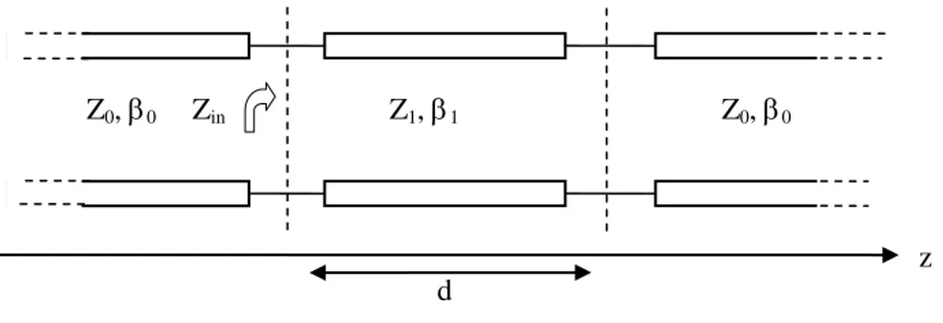
3.1 METAMATERIAL SLABS WITH EXTREME VALUES OF THE CONSTITUTIVE PARAMETERS In this Section, results obtained in Section 2.4 are applied to the case of an homogenous slab made of a metamaterial with special values of both permittivity and permeability. The thickness of the slab is d and the constitutive parameters are defined as: ε = ε0εr, μ = μ0μr. Considering a plane wave excitation, in the case of a TEM(z), TE(z), TM(z) linear polarizations and angle of incidence θinc a TL- equivalent representation is given:
Figure 7 TL-equivalent representation of a plane wave impinging on a metamaterial dielectric slab in free space.
The reflection coefficient R at the first interface is evaluated:
2 2 1 0 1 2 2 1 0 1 0 1 Z Z tan d R Z Z tan d 2 j Z Z (3.1)where Z0 is the intrinsic impedance of the vacuum, Z1 the intrinsic impedance of the metamaterial, β0 the vacuum wave-number, β1 the wave-number in the metamaterial slab. In the following, we will consider two special cases, assuming εr and μr to be real values for simplicity (this assumption is in general incorrect, and an imaginary part is always required in the case of dispersive materials to satisfy Kramers-Kronig relations [8], however it becomes acceptable in case of a point analysis):
r 0 r lim R, lim R (3.2) Zin z Z1, 1 Z0, 0 Z0, 0 d
__________________________________________________________________________
Luca Scorrano: Progetto di Metamateriali per Applicazioni alle Telecomunicazioni 29
3.1.1 TEM(z) polarization
In the case of a TEM polarized wave travelling along the transmission line, the characteristic impedances and the wave-numbers are given by:
0 0 0 0 r r 1 0 0 r r 0 0 0 1 0 r 0 r 0 r r Z Z Z (3.3)
The reflection coefficient (3.1) is then evaluated:
r r r r r r 0 r T 0 EM r r ( ) R ( ) j2 Cot[ ] d ω (3.4)
Through the explicit calculation of limits (3.2) the following results are achieved:
0 r 3/ T 0 r 2 3/2 0 0 r 0 0 r EM 0R j li 2 m d ω d ω (3.5) r TEM lim R 1 (3.6)
Interestingly, both (3.5) and (3.6) lead to the same fundamental results, however, with significant differences. Under proper assumptions, in fact, it is possible to achieve an Artificial Magnetic Conductor (AMC) condition in both cases, but, in order to allow a physical implementation of such materials the magnitude of the slab thickness, electric permittivity and magnetic permeability play an important role.
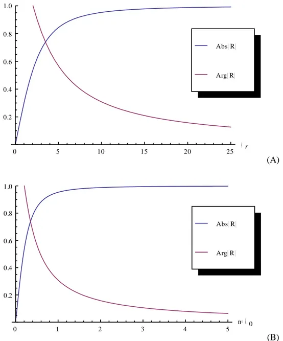
In the case of (3.5) the AMC condition is achieved, provided moderately high values of permeability (μr >25 to have Abs[R]>0.95 and Arg[R]~0.1) or moderately high values of the screen thickness.
__________________________________________________________________________
Luca Scorrano: Progetto di Metamateriali per Applicazioni alle Telecomunicazioni 30
0 5 10 15 20 25 r 0.2 0.4 0.6 0.8 1.0 Arg R Abs R (A) 0 1 2 3 4 5 n 0 0.2 0.4 0.6 0.8 1.0 Arg R Abs R (B)
Figure 8 Variation of the reflection coefficient amplitude and phase when r 0with (A) the relative permeability and an electrically thin slab (d = λ0/10), with (B) the slab relative thickness (as fractions of λ0) and μr = 1 at a frequency of 3GHz.
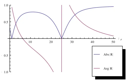
In the case of (3.6) the AMC condition is achieved, provided only very high values of magnetic permeability, but the convergence of the limit is achieved through an highly oscillating trend depending on all the significant parameters of the slab.
__________________________________________________________________________
Luca Scorrano: Progetto di Metamateriali per Applicazioni alle Telecomunicazioni 31
10 20 30 40 50 r 1.0 0.5 0.5 1.0 Arg R Abs R
Figure 9 Variation of the reflection coefficient amplitude and phase when r with an electrically thin slab (d = λ0/10) and εr =1 at a frequency of 3GHz.
3.1.2 TE(z) polarization
Let us assume the case of a TE(z) polarization. The expressions of the intrinsic impedances and wave-numbers are now:
TE TE 0 0 0 TE TE 1 0 r 1 TE 2 2 0 0 x TE 2 2 1 1 x x 0 inc Z / Z / k k k sin (3.7)
being kx the transverse wave-number and θinc the angle of incidence on the xz plane. In this case, the condition required to have an AMC behavior, regardless of the thickness of the slab, is again the following:
r
TE
__________________________________________________________________________
Luca Scorrano: Progetto di Metamateriali per Applicazioni alle Telecomunicazioni 32
0.2 0.4 0.6 0.8 1.0 inc 0.2 0.4 0.6 0.8 Arg R Abs R
Figure 10 Variation of the reflection coefficient amplitude and phase when 0 <θinc < π/3, for an electrically thin slab (d = λ0/10), μr = 50 and εr =1, at a frequency of 3GHz.
The metamaterial slab should then exhibit a large relative permeability, growing as the maximum allowed incident angle grows.
In case of a vanishing electric permittivity instead:
r TE 0 2 2 2 2 r r 0 1 2 2 2 1 0 2 2 r 0 0 0 0 0 0 ( 1 )Sin A A A r Cos2j Cos Coth[ Sin ]
lim R
A d ω Sin Sin
(3.9)
The AMC-like behavior is still found, similarly to the TEM(z) case, provided, again, a sufficiently high thickness of the metamaterial slab, but only for small incidence angles (θinc < π/6).
__________________________________________________________________________
Luca Scorrano: Progetto di Metamateriali per Applicazioni alle Telecomunicazioni 33
0.0 0.1 0.2 0.3 0.4 0.5 inc 0.2 0.4 0.6 0.8 1.0 Arg R Abs R
Figure 11 Variation of the reflection coefficient amplitude and phase when 0 <θinc < π/6, for an electrically thick slab (d = 2 λ0), μr = 1 and εr →0, at a frequency of 3GHz.
The AMC-like behavior of the material slab, in case of a vanishing electric permittivity, improves as the thickness d grows, similarly to what has been found for the TEM(z).
3.1.3 TM(z) polarization
In the case of a TM polarized impinging wave, the parameters of the lines are:
TM TM 0 0 0 TM TM 1 1 0 r TM 2 2 0 0 x TM 2 2 1 1 x x 0 inc Z / Z / k k k sin (3.10)Interestingly, for this particular polarization, it is always found:
r TM 0 lim R 1 (3.11) r TM lim R 1 (3.12)
__________________________________________________________________________
Luca Scorrano: Progetto di Metamateriali per Applicazioni alle Telecomunicazioni 34
regardless of the actual value of both the angle of incidence and the thickness of the slab. However, in real-life structures the tolerance of the structures to a mismatching of the electrical parameters plays an important role, in Figure 12 the effect of small variations of the electric permittivity is shown.
0.05 0.10 0.15 0.20 0.25 r 1.0 0.5 0.5 1.0 Arg R Abs R
Figure 12 Variation of the reflection coefficient amplitude and phase with electric permittivity, for an electrically thin slab (d = λ0/10), μr = 1 and θinc = π/4, at a frequency of 3GHz.
0.2 0.4 0.6 0.8 inc 1.0 0.5 0.5 1.0 Arg R Abs R
Figure 13 Variation of the reflection coefficient amplitude and phase when 0 < θinc < π/6, for an electrically thin slab (d = λ0/10), μr = 1 and εr =1/100, at a frequency of 3GHz.
Figure 13 also suggests the use of a epsilon near zero slab as a spatial filter. In case of electrically thin screens and small values of the electric permittivity the screen reflects all
__________________________________________________________________________
Luca Scorrano: Progetto di Metamateriali per Applicazioni alle Telecomunicazioni 35
the components of an impinging radiation characterized by |θinc|< Δθ letting the others pass through. The angle Δθ decreases as the electric permittivity vanishes:
0.0 0.2 0.4 0.6 0.8 inc 0.2 0.4 0.6 0.8 1.0 r 1 10000 r 1 1000 r 1 100 r 1 10
Figure 14 Variation of the reflection coefficient amplitude and phase when 0 < θinc < π/4, for an electrically thick slab (d = λ0/10), μr = 1 and θinc = π/4, at a frequency of 3GHz.
An approximated analytical solution for Δθ is found:
r r /2 ArcSin 2 C 1 C (3.13)
__________________________________________________________________________
Luca Scorrano: Progetto di Metamateriali per Applicazioni alle Telecomunicazioni 36
3.2 EPSILON NEAR ZERO REFLECTORS AT THZ
From the result achieved in Section 3.1, the design details of AMCs at THz scale is illustrated through the employment of volumetric metamaterials. At the microwave frequencies, it is known from literature [37] that AMCs can be obtained through the use of high-impedance surfaces (HISs), which are complex profile metallic surfaces exhibiting noticeably high values of the surface impedance in a given frequency range.
The idea of using volumetric metamaterials at microwaves to design HISs has been already presented in [38]. However the characteristic dispersion and losses affecting real-life materials suggest the use of those structures more in the field of absorbers [39] (even if characterized by a narrow bandwidth yet small size in comparison to a Salisbury screen absorber [40]) than in that of reflectors. In addition, in the frequency ranges where natural magnetism is achieved, such magnetic materials like ferrites may be applied to get the desired AMC-like behavior; anyway, natural magnetism is no longer available as the frequency increases, and artificial magnetic materials have to be designed.
In [41] the possibility to synthesize AMCs in the visible regime is described and an application to nano-antennas is proposed: the idea is to get directive optical nano-radiators. In [42,43], in fact, plasmonic nano-dipoles and Hertzian nano-dimers have been studied to reproduce at higher frequencies the radiation properties of typical radio-frequency antennas. In order to get directive optical radiators, an ENZ material is a suitable candidate to design reflectors working in the visible. The antenna can be then placed in close proximity to the reflector, resulting thus in a very compact setup. Even if at visible frequencies it is hard to find natural materials with low values of permittivity, it is possible to synthesize an artificial ENZ media through properly designed multi layered structures made of plasmonic and non-plasmonic slabs, as already presented in [44,45] for different applications. If the thicknesses of the layers are electrically small, the resulting medium may be described through effective constitutive parameters depending on the thickness ratio and the relative permittivity of the two materials (the thickness is assumed along the z axis, while x and y subscripts refer to the transverse directions):
__________________________________________________________________________
Luca Scorrano: Progetto di Metamateriali per Applicazioni alle Telecomunicazioni 37
1 2 1 2 2 1 1 1 1 1 x y z d d (3.14)
In Figure 15 and Figure 16, the directivity of a silver plasmonic nano-dipole with an ENZ reflector is shown. h 1 d 2 d L Ag 2 SiO D 0 90 (a) (b)
Figure 15 a) Layout of a nano-dipole of length L=160 nm backed by a layered medium of thickness D = 125 nm at a distance h = 3 nm. The transverse size of the layered screen is λ0xλ0, and it is made of 10 pairs of slabs of silica (d1=10 nm) and silver (d2= 2.5 nm). b) Radiation patterns of the antenna at the operating frequency of 600 THz on the two principle planes. (Pictures from ref. 41)
__________________________________________________________________________
Luca Scorrano: Progetto di Metamateriali per Applicazioni alle Telecomunicazioni 38
Figure 16 3D radiation pattern of the silver nano-dipole backed by an ENZ reflector synthesized through stacked alternating layers of plasmonic and non plasmonic materials. The geometric parameters are the same as in Figure 15. (Pictures from ref. 41)
3.3 NEAR FIELD PATTERN SYNTHESIS TROUGH NANO-CIRCUIT SURFACES
In this Section, the design of a reactive artificial screen is studied to synthesize a prescribed field patter at optical frequencies as shown in [46,47]. The screen, designed according to the recently proposed new concept of nanocircuit, consists in a discrete set of dielectric cells,. The spatial distribution of the cells is tuned to allow the focalization of a sub-wavelength spot beyond the diffraction limit at a prescribed focal distance.
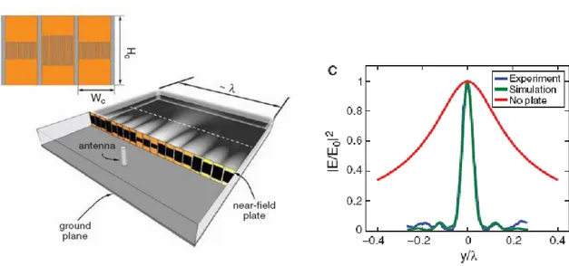
The use of complex engineered artificial surfaces has been experimentally demonstrated at microwaves by Merlin [48,49]. This kind of surfaces are able to modify the phase front of an incident wave (of prescribed polarization), reconstructing a target sub-wavelength pattern at a given distance in the near field.
__________________________________________________________________________
Luca Scorrano: Progetto di Metamateriali per Applicazioni alle Telecomunicazioni 39
Figure 17 Experimental setup proposed by Merlin, consisting in the juxtaposition of interdigital capacitors of proper value. (Pictures from ref. 49)
At optical frequencies, the synthesis of patterns with sub-wavelength features has been demonstrated through the use of Fresnel Zone plates with metallic coatings [50], in [46,47] instead, an inhomogeneous spatial distribution of the electric permittivity
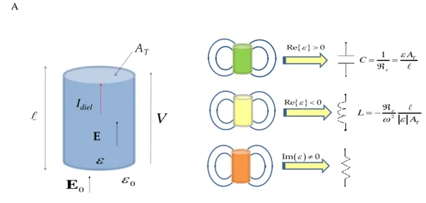
x y, is used. Moreover, the possibility to achieve a sub-wavelength desired pattern at arbitrary distances is suggested in [46,47] by using active media. The extreme values of the required distribution of permittivity can be obtained in principle through the recent advancements in metamaterial technology, allowing the fabrication of extremely miniaturized cells exhibiting both high values of reactance and a tunable active behavior.The unit cells forming the screen are made of a dielectric materials with certain electric parameters and they are characterized by sub-wavelength dimensions. According to the theory developed in [27], for a given polarization of the field impinging on such an elements, it is possible to derive the corresponding element impedance, by replacing the conductive current by the displacement current and defining, this way, a voltage drop across the nano-element. The current flowing though the cross-section of the element in Fig. 2 can be written as:
diel E T T
A
__________________________________________________________________________
Luca Scorrano: Progetto di Metamateriali per Applicazioni alle Telecomunicazioni 40 while the voltage drop along the nano-element is given by:
A V
E dl E (3.16) AT E IdielV
0 0 E Im 0 Re 0 1 T e A C Re 0 2 e T L A AT E
IdielV
0
0 E Im 0 Re 0 1 T e A C Re 0 2 e T L AFigure 18 The dielectric cell realizing a reactive element at optical frequencies. Its circuit behavior is mainly determined by the sign of the real part of the electric permittivity and by its imaginary part. (Pictures from ref. 47)
The corresponding impedance is then given by:
e e diel e T V 1 V 1 Z , I i i A (3.17)
where ε is the permittivity of the material, AT the cross-section of the nano-element and ℓ its height. In [27] it is shown that if 0 this nano-element behaves like a capacitor, while if 0 it behaves as an inductor, and if 0 like an insulator being D=0.
The expressions (3.15) and (3.16) are valid under the assumption that the leakage flux through the element can be neglected, having assumed the current along the nano-element axis as uniform; moreover, any coupling among the nano-elements must be avoided. It is known from [48,49] that once
x y, is obtained, the impedance spatial distribution must be sampled, assuming each element, whose effective impedance value samples
x, y , to be electrically close to the others and the focal plane distance to be small compared to the wavelength. This way, the negative real part of
x y, can be neglected,__________________________________________________________________________
Luca Scorrano: Progetto di Metamateriali per Applicazioni alle Telecomunicazioni 41
fact that implies the passivity of the proposed device (otherwise, in order to get a sub-wavelength pattern synthesis in far-zone some form of amplification is needed), and
x , y at the sample points turns to be purely capacitive. The proper value of the i i capacitance for each cell of the screen is then found from (3.17) as:
T
A
C (3.18)
In addition, the electric flux E couples elements electrically close to the others, establishing unwanted series and parallel connections [27]. In order to reduce both the coupling among the cells and the electric flux leakage, an epsilon-near-zero cover must be used [51]. Therefore, the final layout of the unit cell is as follows: an inner dielectric element with an electric permittivity 0, which realizes the sampled value of the screen capacitance at a certain point, surrounded by an outer cover with an electric permittivity
0, realizing the insulator as depicted in Figure 19.
h
d w
Figure 19 The final layout of the cell realizing a capacitance sampled value on the screen. The outer cover implements the insulator. The inner dielectric box represents the capacitive element. The unit cell size is 12.5 nm×25 nm×5 nm (w×h×d). (Pictures from ref. 47).
__________________________________________________________________________
Luca Scorrano: Progetto di Metamateriali per Applicazioni alle Telecomunicazioni 42
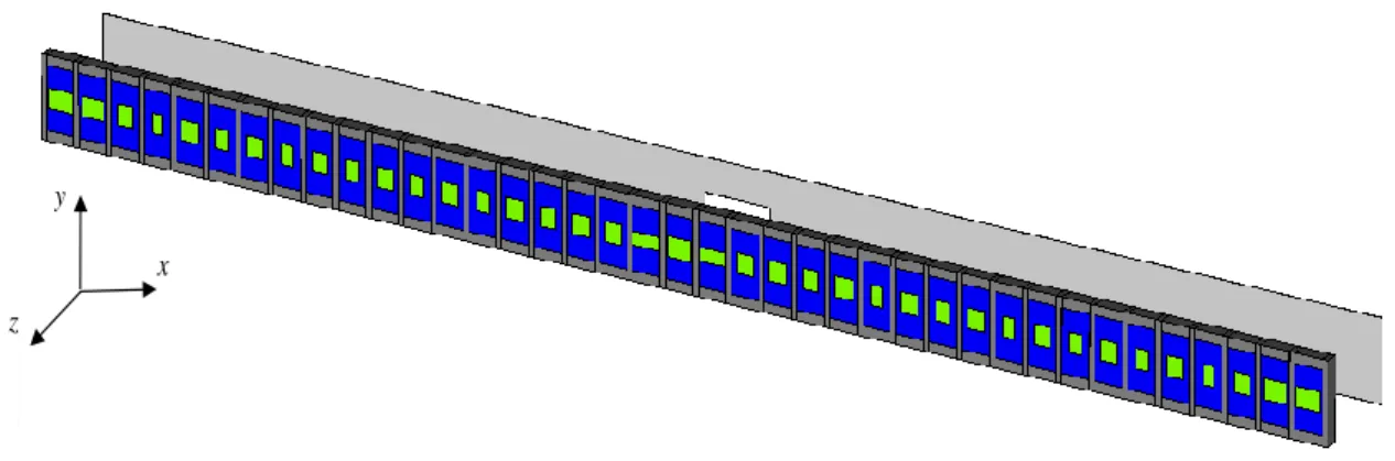
Figure 20 Actual implementation of a 1D reactive screen working at optical frequency. (Pictures from ref. 47).
Assuming we want to synthesize the following 1-D field pattern at the plane zz0:
0 res synt z z 0 sin k x ˆ x A x E y (3.19)where kres 2 / d and λd is the sub-wavelength resolution of the surface. In order to keep the design of the screen as simple as possible, all the elements are required to be made of the same dielectric material (silicon carbide). The design frequency has been set to f0=600 THz, where the silicon carbide exhibits a relative permittivity of εr=7.1. This high value of
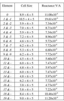
εr results in a significant reduction of the screen thickness. The reactive values, required to synthesize the pattern described by (3.19), are obtained by tuning the dimensions of each element. Accordingly to [46,47,48,49] the following values of dielectric cell reactance are found:
__________________________________________________________________________
Luca Scorrano: Progetto di Metamateriali per Applicazioni alle Telecomunicazioni 43
TABLE II
Element Cell Size Reactance V/A 0 8.9 × 6 × 5 11.08x10⁻⁶ 1 & -1 10.5 × 4 × 5 19.61x10⁻⁶ 2 & -2 5.9 × 6 × 5 7.34x10⁻⁶ 3 & -3 7.0 × 6 × 5 8.71x10⁻⁶ 4 & -4 5.9 × 6 × 5 7.34x10⁻⁶ 5 & -5 7.2 × 6 × 5 8.96x10⁻⁶ 6 & -6 4.6 × 6 × 5 5.72x10⁻⁶ 7 & -7 6.2 × 6 × 5 7.72x10⁻⁶ 8 & -8 5.3 × 6 × 5 6.60x10⁻⁶ 9 & -9 6.2 × 6 × 5 7.72x10⁻⁶ 10 & -10 4.5 × 6 × 5 5.60x10⁻⁶ 11 & -11 6.0 × 6 × 5 7.47x10⁻⁶ 12 & -12 4.8 × 6 × 5 5.97x10⁻⁶ 13 & -13 6.0 × 6 × 5 7.47x10⁻⁶ 14 & -14 4.8 × 6 × 5 5.97x10⁻⁶ 15 & -15 6.2 × 6 × 5 7.72x10⁻⁶ 16 & -16 3.8 × 6 × 5 4.73x10⁻⁶ 17 & -17 5.8 × 6 × 5 7.22x10⁻⁶ 18 & -18 8.4 × 6 × 5 10.46x10⁻⁶ 19 & -19 9.0 × 6 × 5 11.20x10⁻⁶
Impedance values of the meta-screen cells
The structure shown in Figure 21 is excited by an electrically small horizontal slit (25 nm
× 5 nm) on an opaque screen illuminated by a plane TEM wave, placed 35 nm apart from
the reactive screen (see Fig. 5). The focusing plane is set at a distance z0=35 nm from the
screen along the positive propagation axis, and the corresponding amplitude of the y component of the electric field at 600 THz is reported in Figure 22