Alma Mater Studiorum – University of Bologna
SCIENCE UNIVERSITY
Department of Industrial Chemistry “Toso Montanari”
Master’s Degree in
Industrial Chemistry
Class LM-71 – Science and Industrial Chemistry Technology
Electrodeposition of actives species on
carbonaceous materials for energy applications
CANDIDATE
Diana Elena CiurducSUPERVISOR
Illustrious Professor: Marco Giorgetti
CO SUPERVISOR
Illustrious Professor: Eduardo Enciso Rodrìguez Dino Tonti
_______________________________________________________________________
Academic Year 2016-2017
_______________________________________________________________________ Session II
3 Abstarct
The thesis work focuses on the electrosynthesis of active species on carbonaceous materials, their characterization and energy applications. Two protocols of electrochemical synthesis that lead to two forms of hexacyanoferrate copper (CuHCF) with different composition and structure, were applied. The procedure used is a “two – step” method that involves the deposition of metallic copper and the subsequent anodization in the presence of ferricyanide ion, using as support graphite sheet, carbon cloth and carbon toray paper. Another protocol was that of electrosynthesis of double layer hydroxide (LDH) containing cobalt as bivalent cation and aluminium or iron as trivalent metal, using as support graphite sheet, carbon cloth, carbon toray paper and nickel foam. After studying the correlation between the electrodeposition time and the masses obtained, the specific capacities of the deposited materials were calculated. The last used protocol was the electrochemical synthesis of nickel hexacyanoferrate on nickel foam. All the film obtained were electrochemically characterized by cyclic voltammetry. SEM – EDX and XRD analyses were performed on some samples in order to obtain morphological and chemical informations.
Some tests were conducted using the supports or some of the electrodeposited samples as cathodes in lithium – air batteries, to understand their potential as sources of energy. After performing oxygen and argon cyclic voltammetries, controlling in what way the potential change at different current density and carrying out full discharge at constant current density (0.02 mA/cm2), it was found that the carbon tissue was the one that produced the best results. So it was decided to study in deep the behaviour of this support when active species are electrodeposited above it.
As a parallel work, attempts were made to obtain porous carbon from hair, with the intention of using it as a support, in a slurry for example, for testing electrodepositions of active species mentioned above. Despite the porosity being tested through nitrogen adsorption isotherms and good results have been achieved, it has not been enough time to find the right slurry with which to conduct the electrodepositions.
4
Sommario
INTRODUCTION………...7
1.1 Hexacyanoferrate of transition metals ... 7
1.1.1. Prussian Blue... 7
1.1.2. Copper Hexacyanoferrate ... 10
1.1.3 Synthesis of Copper Hexacyanoferrate ... 11
Synthesis in Bulk ... 11
Synthesis on a conductive substrate ... 12
1.1.4 Electrochemical and morphological characterization ... 13
Electrochemical characterization ... 13
Morphological characterization ... 14
1.2 Nickel Hexacyanoferrate ... 14
1.3 Layered double hydroxides ... 15
1.3.1 Synthesis methods of double layer hydroxide ... 17
1.4 Conductor substrates ... 19
1.4.1 Graphite sheets ... 19
1.4.2. Carbon Paper Gas Diffusion Layers (GDL) ... 20
1.4.3. Carbon Cloth Gas Diffusion Layers ... 21
1.4.4. Glassy Carbon ... 22 1.4.5. Nickel foam ... 22 1.5 Hair ... 23 1.6 Applications ... 23 1.6.1 Batteries ... 23 1.6.2 Electrochemical Capacitors ... 25 Pseudo-capacitors ... 26 MOTIVATION………..28 EXPERIMENTAL PART………. 29
5
3.1.1 Graphite Sheets ... 29
3.1.2 Carbon Cloth, Carbon Paper and Nickel foam ... 29
3.1.3 Glassy Carbon Electrode (GCE) ... 29
3.2 Materials, substances and instrumentation ... 30
3.3 Copper Hexacyanoferrate ... 31
3.3.1 Deposition of metallic Cu and anodization in presence of ferricyanide ion .. 31
3.3.2 Electrochemical Characterization ... 32
3.4 Nickel Hexacyanoferrate ... 32
3.5 Layered double hydroxides (LDH) ... 32
3.5.1 Co/Al LDH ... 32
3.5.2 Co/Fe LDH ... 32
3.6 Hair ... 33
3.6.1 Adsorption isotherms ... 33
3.7 Electrochemical techniques used ... 35
3.7.1 Chronoamperometry ... 35
3.7.2 Cyclic Voltammetry ... 36
3.8 Chemical and morphological characterization ... 37
3.8.1 SEM – EDX ... 37
3.8.2 XRD – X Ray Diffraction ... 38
3.9 Batteries ... 38
3.10 Data processing ... 39
RESULTS AND DISCUSSION………40
4.1 Metallic Cu deposition and anodization in presence of ferricyanide ion (CuHCF)... ... 40
4.2 Nickel Hexacyanoferrate (NiHCF) ... 48
4.3 Double Layer Hydroxide (LDH) ... 51
4.3.1 Cobalt Aluminium (CoAl) ... 51
6
4.4 Morphological and structural characterization ... 61
4.4.1 SEM/EDX ... 61
4.4.2 XRD ... 64
4.5 Testing the materials in a battery assembly ... 65
4.6 Hair as a substrate ... 70
CONCLUSIONS... ………... 73
BIBLIOGRAPHY... 74
7
Chapter 1: Introduction
The purpose of this introduction is to give a comprehensive overview of the techniques and tools used to develop this thesis work.
1.1 Hexacyanoferrate of transition metals
When we talk about hexacyanoferrate of transition metals we refer to a category of inorganic compounds of general formula AxMy[Fe(CN)6] * zH2O, with M = metal of
transition, A = countercation, belonging to the largest family of compounds called hexacyano metallates.
1.1.1. Prussian Blue
In this class of compounds, the first and most studied is the hexacyanoferrate (II) of iron (III), also known as Prussian Blue (PB). Its synthesis is reported in the literature of the early 18th century (1), making it one of the first coordinating compounds to be obtained synthetically and one of the oldest inorganic pigments produced industrially (2).
The “soluble” KFeIIIFeII(CN)
6 form is obtained when K4[Fe(CN)6] is mixed in a 1 : 1
solution with Fe3+ [1.1] or inversely when K3[Fe(CN)6] is put in solution with a Fe2+ salt
[1.2]. The structure thus obtained is the more regular and free from defects even if in both cases a colloidal solution is obtained. The soluble term was introduced by paint manufacturers, referring to the easiness with which Potassium salts form colloidal solutions (peptization).
𝐹𝑒3++ 𝐾4[𝐹𝑒𝐼𝐼(𝐶𝑁)
6] → 3𝐾++ 𝐾[𝐹𝑒𝐼𝐼𝐼𝐹𝑒𝐼𝐼(𝐶𝑁)6] [1.1]
𝐹𝑒2++ 𝐾3[𝐹𝑒𝐼𝐼𝐼(𝐶𝑁)6] → 2𝐾++ 𝐾[𝐹𝑒𝐼𝐼𝐼𝐹𝑒𝐼𝐼(𝐶𝑁)6] [1.2]
The “insoluble” form Fe4[Fe(CN)6]3 is obtained when Fe3+ or Fe2+ salts are added in excess
to a solution of anions [Fe(CN)6]4- or [Fe(CN)6]3-, obtaining in the first case the Blues of
Prussia and in the second the Blue of Turnbull (3). It has been demonstrated, through XRD analysis and electron diffraction, as the two compounds possess the same structure (4). The tonal difference resides purely in the precipitation method, which affects the size of the particles and the content of impurities.
8 The soluble and insoluble terms, however, should not be understood in the real sense of terms, but rather refer to the ability or not to form colloidal solutions. Such propriety is due to the presence or not, respectively, of interstitial cavity. (5)
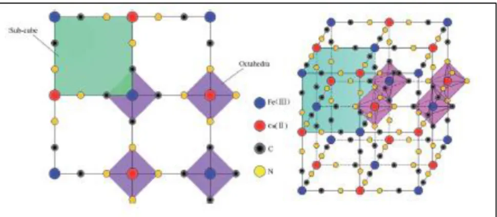
The first to study the structure of the copper hexacyanoferrate were Keggin and Milles (6)
through X-ray diffraction. The structure in Figure 1.1 is a face centered cubic structure (fcc) where Fe2+ and Fe3+ ions are connected via bridges of −𝐶 ≡ 𝑁 − forming a bond of type FeII – CN – FeIII. The cell length is about 10 Å. Studies by IR and Mössbauer have
made it possible to establish definitively that in ferric ferrocyanide the iron atom coordinated to the carbon is a low spin Fe2+, while the iron coordinated to the nitrogen is
a high spin Fe3+(7) (8).
The structure of the insoluble form was determined by Ludi et all (9). They found it a greater structural disorder caused by the fact that a quarter of the sites destined to ferrocyanide is not occupied. The sites that present deficiencies of [Fe(CN)6]4- ions are
occupied by water molecules. The structure contains three different coordination iron sites: FeIIC6, FeIIIN6 and FeIIIN4(H2O) in a 3 : 1 : 3 ratio.
Figura 1.1: In the figure, a part of the cubic lattice characterictic of hexagonal metal. The possible defect
and intercalated molecules or ions are not shown. When M = FeIII and M’ = FeII, we obtain the classic
idealized structure of Prussian Blue.
The intense blue color is due to the transfer of electrons between the ions [FeII(CN)6]4- and
Fe3+. In fact if the centers of Fe3+ are completely reduced to Fe2+ we obtain the white salt of K4F4III[FeII(CN)6]3, called Prussian White (PW) or Everitt’s salt. If on reverse the centers
of Fe2+ are oxidezed at Fe3+ we obtain Fe4III[FeIII(CN)6]3, called also Prussian Yellow (PY).
A partial oxidation leads to Green of Berlin (BG).
The interest in this category of compounds rised thanks to Neff’s electrochemical studies
(10), he deposited for the first time a slim film of Prussian Blue attached to a conductive material. He observed how the deposit could be oxidezed and reduced in response to a variation in the electrochemical potential.
9 Electronic transfer reactions are accompanied by transfer of cations inside and outside the structure so the charge balance is kept neutral. In the case of Prussian Blue, the reduction of iron centers involves the insertion of alkali metal cations in the inserstitial positions. [1.3]
𝐹𝑒4𝐼𝐼𝐼[𝐹𝑒𝐼𝐼(𝐶𝑁)
6]3+ 4𝑒−+ 4𝐾+ ↔ 𝐾4𝐹𝑒4𝐼𝐼[𝐹𝑒𝐼𝐼(𝐶𝑁)6]3 [1.3]
During oxidation, alkaline metal cations leave the lattice and go back in solution. Going from Prussian White to Prussian Blue, the cations go out of the grid, for this reason it is believed that further oxidation to Green of Berlin and Prussian Yellow involves the insertion of anions. (11) [1.4]
𝐹𝑒4𝐼𝐼𝐼[𝐹𝑒𝐼𝐼(𝐶𝑁)
6]3+ 3𝑒−+ 3𝐴− ↔ 𝐹𝑒4𝐼𝐼𝐼[𝐹𝑒𝐼𝐼(𝐶𝑁)6𝐴]3 [1.3]
Prussian Blue films were deposited for simple dipping (10) (12), electrochemical deposition in galvanostatic way (13), potentiodynamic (14), potentiostatic (15) (16) (17) (18), and through plasma techiques combined with electrochemical methods (19). The different deposition mechanisms of Prussian Blue on a conductive support are reported in literature by some authors (12) (20) (21). In the non – electrochemical process it has been hupothesized that the formation of Prussian Blue is associated with the oxidation of the conductive support due to the complex FeIII[FeIII(CN)6]. The immersion of a conductive
support in a solution like FeCl3 e K3Fe(CN)6 has a very positive OCP which is not achieved
in a solution contaning only one of these two salts. We can conclude that the solution consisting of both salts is a strong oxidant.
The potentiodynamic deposition is believed to be based on two mechanisms: in the first the potential of +0.7V is reached in the cathodic direction and the Prussian Blue is deposited thanks to the reduction of the FeIII[FeIII(CN)
6]complex, while in the second at a
potential of +0.4V the Fe3+ ions are reduced to Fe2+ ions on the nude electrode. The Fe2+ reacting with the ferricyanide ions caused the precipitation of Prussian Blue.
A furher strategy is to deposit a metallic iron film on the conducting substrate, oxidazing it in a solution of K4Fe(CN)6 by the potentiostatic or potentiodynamic way (22). The
supersaturation of the Fe3+ ion that is created near the surface of the electrode allows the deposition of the Prussian Blue. It is also possible to deposit Prussian Blue from a solution containing only [Fe(CN)6]3-. By favoring the acid pH condition, the ferrocyanide anion
dissociates; the Fe3+ is reduced to Fe2+ on the surface of the electrode forming Prussian Blue (23). Galvanostatic methods are based on the same mechanisms as the previous ones; apply one determined current density for a certain period of time, during which the potential of the electrode changes. The driving force is never the same and the film that is
10 formed coould have different shapes or structures when compared with the methods that allow to controle the potential.
The interest for this compound has led to the synthesis of countless analogies where Fe3+ ion is replaced by transition metals such as Cu (24), Pd (25), In (26), Pt (27), Cr (28), Ni
(29), Co (30), V (31),Zn (32), Ga (33), Mn (34). In addition to the possibility of create hexacyanoferrates of mixed metals, such as CuPdHCF (35), CuCoHCF (36), NiPdHCF
(37), NiCoHCF (38), FeRuHCF (39), recently have also been synthesized compounds based on rare earths (40).
1.1.2. Copper Hexacyanoferrate
The copper hexacyanoferrate (CuHCF) is one of the most studied Prussian Blue’s analogs. Its synthesis is reported in literature from the end of the XIX century, and with this synthesis they performed perhaps the oldest semi-permeable membrane for studies on osmotic equilibrium (41). In the article of 1963 by Keggin and Miles (6) the structure in the Figure 1.2 is common to that of the Prussian Blue. The structure can be referred to CuHCF in the “soluble” form or in the “insoluble” one. The “soluble” form has a typical face centered cubic structure, in which the iron is bonded to the carbon while the copper is bonded to the nitrogen (𝐹𝑒 − 𝐶 ≡ 𝑁 − 𝐶𝑢). The “insoluble” form has a similar cubic structure to the previously described one, but with a quarter of the sites for [Fe(CN)6]
4-unused and water molecules in the empty positions to complete the coordination shell of Cu (42).
The substitution of Fe3+ with Cu2+ produces a distorted and more opened structure that the Prussian Blue one. This feature has raised the interest in this compound since it is capable of interacting with a wider range of ions and for the ability to exploit the couple Cu2+/Cu+ for the electrocatalysis of many compounds.
Figure 1.2: Structure of CuHCF (43) a0 around 10 Å, and it is twice the distance between the Fe and Cu
11 The molecular formula is generally represented as Cu3II[FeIII(CN)6]2 * xH2O for the
oxidized species and K2Cu3II[FeII(CN)6]2 * xH2O for the reduced species. The results
obtained from Ayrault et al (44) (45) show how the reduced form of CuHCF is composed of two different components: Cu2II[FeII(CN)6] and K2CuII[Fe(CN)6]. The oxidized form
and the first of the two reduced ones were determined by X-ray diffraction (XRD), the second reduced one remained indeterminate since one singe crystal cannot be obtained. The CuHCF was deposited for the first time on a glassy carbon electrode by Siperko and Kuwana (24), who identified by cycling voltammetry the set of peaks at about +0.7V corresponding to the oxidation and reduction of the iron from the hexacyanoferrate. Subsequently Shankaran (46) observed a second electrochemical process with more negative potentials belonging to the pair of Cu2+ / Cu+, confirmed later by Makowski (47). The redox processes, as for the other hexacyanoferrate occur with the participation of cations, although, through studies with EQCM and PBD in situ was hypothesized the participation of anions and/or solvents to a lesser extent (27). The reducing semi-reaction of a CuHCF film can be represented in general as follows:
𝐶𝑢3[𝐹𝑒𝐼𝐼𝐼(𝐶𝑁)
6]2+ 2𝑒−+ 2𝐾+ → 𝐾2𝐶𝑢3[𝐹𝑒𝐼𝐼(𝐶𝑁)6]2 [1.5]
1.1.3
Synthesis of Copper Hexacyanoferrate
In general for the synthesis of CuHCF, we can distinguish between precipitation in the “bulk” of the solution and precipitation preferentially on a conducting substrate.
Synthesis in Bulk
Precipitation method: this method is most used and has many variants depending on the starting salts present in the solution. In general, the precipitation occurs by mixing a solution of Cu2+ salt with a solution of hexacyanoferrate (II) or (III) ions derived from the alkali metallic salts of from the ferrocyanide acid. It is important to pay attention to the ratio between cations and hexacyanoferrate ions that leads, as appropriate, to compounds with different structure. The normal procedure consists in add the solutions of the two salts to a third one, in order to control the selected stoichiometry.
Starting from hexacyanoferrate (II) salts we obtain a compound with a cubic shape, which present a Cu3II[FeIII(CN)6]2 formula which represents its oxidized form. In
this form we can find cations intercalated in the structure and water molecules in variable quantity. Instead, starting from hexacyanoferrate (II) salts, we obtain the
12 reduced form Cu2II[FeII(CN)6]2 which presents a greater amount of intercalated
cations. Using lithium salts we are able to obtain the pure compound in this stage, since they don’t intercalate into the structure (44).
Method through Local Growth: For this kind of synthesis you can follow two procedures:
o The hexacyanoferrate crystals of an alkaline metal are added in a concentrate solution of copper nitrate or copper sulphate
o Copper sulphate crystals are added to a concentrated solution of an alkaline metal hexacyanoferrate. An insoluble film of the hexacyanoferrate is formed around the growing crystal that grows thick until the starting solid is completely consumed. This method results in a greater amount of potassium ions in the lattice, and we are able to obtain the pure phase K2CuIIFeII(CN)6.
At the end of both the synthesis we proceed with decantation or centrifugation, then the precipitate is filtered, washed and left to dry. With bulk synthesis we can get more material and this method is often used when we need to get a fair amount of substance. The powders obtained with this procedure can be used as modifiers of a conducting substrate. Some precipitate granules can be immobilized on the electrode surface through some techniques which can go from simple abrasion to the use of PIGE (graphite electrodes impregnated with paraffin) (48) or mixed with graphite powder and with a “binder” in order to produce a “carbon paste” electrode (49). There are also cases where the Layer Deposition Layer (LBL) technique was used (50).
Synthesis on a conductive substrate
Dilute solution of starting salts (51): A conducting substrate is immersed in a
solution which contains the hexacyanoferrate ion, the copper ion and a support electrolyte usually formed by salts of sodium or potassium (52). The deposition is done via potentiodynamic, through potential cycles. The film’s growth can follow two ways: the first one provides the meeting between Cu2+ with [Fe(CN)6]3- when
the ferrocyanide is reduced on the surface’s electrode at [Fe(CN)6]4- during
cathodic scan, while the second way occurs through the coagulation process that begins when the two ions Cu2+ with [Fe(CN)6]3- are in contact in the same solution.
Is must be paid attention to the time between the beginning of the voltammetric cycles and the time of insertion of the electrode, since as soon as the electrode in
13 immersed in the solution deposition is already able to start slowly at OCP’s potential. Also the concentration of the two ions is a fundamental parameter, if too high the precipitation in the bulk of the solution will happen quickly and, contrariwise if the concentration would be too low, the coagulation and formation time of the CuHCF film may be excessive. This kind of synthesis has the advantage of being able to adjust the thickness of the film. It is reported that CuHCF can be deposited by potentiodynamic way in solutions that contains cations other than potassium (53).
Metallic deposition of Cu and anodization in presence of [Fe(CN)6]3-(54) (47) (55):
The precipitation occurs during the oxidation of the previously deposited copper film on the surface of the electrode, in presence of [Fe(CN)6]3-. The dissolution of
the film can be done potentially, galvanostatic as well as potentiodynamic. By doing in this way, a supersaturated layer of Cu2+ is formed near the electrode
surface that allows the precipitation of CuHCF on the conductive material. Even in this process the time between the application of the potential and immersion of the electrode must be minimized. The advantage of this method is to obtain a film of remarkable thickness in a short time with the disadvantage of having less reproducibility than other methods.
Open circuit deposition: No potential is applied to the working electrode and deposition occurs spontaneously on the electrode surface. The synthesis occurs only by coagulation and can be performed through different methods. The conductive substrate can be immersed in a solution of the two starting salts for a certain period of time, or you can immerse the electrode in a solution of [Fe(CN)6]
3-after the deposition of a metallic copper film on the same electrode.
1.1.4
Electrochemical and morphological characterization
Transition metal hexacyanoferrate can be characterized by numerous techniques. Below we report an overview of those used in this thesis work.
Electrochemical characterization
In order to characterize the sample electrochemically is necessary to anchor it to a conductive support in one of the ways described in the preceding paragraphs.
Redox processes: Studying redox processes within the film is definitely the most used
14 the electrode on which the hexacyanoferrate is anchored, the redox reactions within the solid that occurs at precise potentials are stimulated, and they allow the recognition of hexacyanoferrate. The most used technique is cyclic voltammetry (CV), whose response consists of a voltammogram with a characteristic form that change according to the type of cation present in the solution (53). In some cases too spacious cation inhibit electrochemical activity, because they are incapable to intercalate in the lattice.
Morphological characterization
To characterize the morphology of hexacyanoferrates Electronic Scanning Microscopy (SEM) (42) was used. The scanning electronic microscopy uses as light source a linear beam of electrons that interact with the surface of the sample creating an image that reflects the surface characteristics of the material. The observation of the images obtained with this technique allows to identify and to interpret the texture of the resins and coals; and although thus technique provides preliminary information of great utility about the shape and dimensions of the material’s porosity.
1.2 Nickel Hexacyanoferrate
One of the others analogues of Prussian Blue is the nickel hexacyanoferrate (NiHCF) and it results particularly indicated for the capture of the cesium (56) (57) (58) because the three-dimensional open structure allows the transport of cations of different sizes to ensure the charge balancing during redox reactions (59). For this reason a number of studies have been carried out on the possible synthesis methods of this compound. Nickel hexacyanoferrate has an adsorptive capacity of 48 %, that means that it succeeds to intercept 0.48 moles of cesium for each mole of NiHCF (60) (61). After discovering the possibility of depositing it electrochemical in a similar way that the one used for the Prussian Blue (62), its structure has been studied and always new materials have been used as substrates to improve their quality and proprieties.
From the structural point of view it has been shown that depending on the synthesis method and the experimental conditions that are used is possible to obtain different products. These studies have been generally conducted in presence of potassium, even if NiHCF can be also successfully deposited using sodium as a counter cation (62). The NiHCF film obtained by electrochemical deposition or by precipitation, are solid solution of two different compounds containing greater or lower quantity of counter cations. While considering the use of potassium, the first is written normally as K2Ni[FeII(CN)6] while for
15 the second the approximate formula KNi1.5[FeII(CN)6] is used. The prevailing structure
depends from the preparation method of the film; the maintenance of a certain constant potential or the application of a variable potential, in fact, lead to obtain respectively the poor structure or a rich one in cation.
Also the time of application of the potential can affect the final product as it has been reported in the literature that at short time correspond the compound K2Ni[FeII(CN)6],
replaced by the other one when the time increases (59). NiHCF may be electrodeposited mainly on inert carriers such as Glassy Carbon (57) (58), gold electrodes and gold plated plastic electrodes (59), or on nickel electrodes of various shapes and sizes (59) (63) (64). By depositing the compound on materials with a high superficial area, it is possible to check the electroactive area and improving its ion exchange capacity. Therefore, NiHCF can be prepared using as electrodes carbon nanotubes coated with a thin film of porous polyaniline (57) or foam Nickel (58).
1.3 Layered double hydroxides
The hydrotalcites (HT) or layered double hydroxides (LDH) are inorganic solids consisting of a layered octahedral structure formed by mixed hydroxides of a bivalent and a trivalent metal (such ad Mg2+ and Al3+). Each layer has an excess of positive charge that is neutralized by intercalated anions in the interlayer space, in conjunction with water molecules, as shown in the figure 1.3.
Figura 1.3: Schematic representation of the LDH structure.
The LDH derived from the natural hydrotalcite, having the formula Mg6Al12(OH)12(CO)3
* 4H2O, have general formula:
[𝑀1−𝑦𝐼𝐼 𝐿𝐼𝐼𝐼𝑦 (𝑂𝐻)2] 𝑦+
[𝑋𝑛−]𝑦
16 Where M and L are respectively the bivalent and trivalent metal that form the octahedral lamellar structure, while X is the intercalated anion in the interstate. LDHs can be synthesized from numerous bivalent and trivalent metals, if they have adequate radius. Of crucial importance are the size of the ion because it should be able to be located in the brucitic layer structure and make octahedral coordination to bind with six hydroxides. For this reason, metallic ions of valence II and III must have similar dimensions to those of Mg2+ and Al3+ and possess electronic characteristics compatible with the octahedral symmetry.
Hydrotalcite compounds are formed by trivalent ion with radius ranging from 0.5 to 0.8 Å and by bivalent ion with radius between 0.65 and 0.80 Å (Table 1). The only exception is Cu2+, which, because of its electronic configuration, doesn’t assume an octahedral symmetry, but forms compounds characterized by tetragonal distortion, for Jahn-Teller effect. In hydrotalcite compounds is possible to insert also metals with inappropriate characteristics, if they are in small percentage. Hydrotalcite compounds can be synthetize with Cu2+ side by side to the bivalent metal that presents the appropriate characteristics for the hydrotalcitic structure.
M (II) Be Mg Cu Ni Co Zn Fe Mn Cd Ca 0.30 0.65 0.69 0.72 0.74 0.74 0.76 0.80 0.97 0.98 M (III) Al Ga Ni Co Fe Mn Cr V Ti In 0.50 0.62 0.62 0.63 0.64 0.66 0.69 0.74 0.76 0.81
Table 1: Ionic rays (Å) of some bivalent and trivalent metal ions.
The ratio between M and L can vary in a relatively large range, because the two ions assume a random distribution in the hydrotalcytic layers. But a pure hydrotalcitic phase can be obtained only if X is between 0.2 and 0.33 because otherwise there would be a hydroxide phase of the excess ion in conjunction with the hydrotalcitic phase. A specific literature (65) as reference point on the molar ratios of the metals is available.
In this work hydrotalcites has been prepared with cobalt, aluminium and iron. It is also important to choose the anion to intercalate in the interstate whose size and nature determine the amplitude of the interstate itself. Since it has to occupy the clay interstates with variable dimensions, the anion used may be of various nature. CO32- is the most
17 layers. Because of these strong interactions, we must make sure that carbonate doesn’t contaminate synthesized hydrotalcite with different anions.
Other anions employed and known in the literature are:
Inorganic anions: F-, Cl-, Br-, I-, ClO
4-, NO3-, ClO3-, IO3-, OH-, CO32-, SO42-, SO4
2-, S2O32-, WO42-, CrO42-, [Fe(CN)6]3-, [Fe(CN)6]4-, [SiO(OH)3];
Iso and heteropolyanions such as (PMo2O40)3-,, (PW12O40)3-, (V10O28)6-;
Anions of organic acids: adipate, oxalate, succinate, malonate;
Anionic metalorganic compounds.
It is possible to synthesize different hydrotalcites for compositional characteristics and structural variables that thus have different reactivity and applications. If we modify, for example, the intercalated anions, it is possible to obtain hydrotalcite with a variable amplitude of the interlayer spacing. The thickness depends on the number, size, orientation and strength of the bonds between the anion and the oxydriles in the brucite layer.
1.3.1
Synthesis methods of double layer hydroxide
LDH electrodes for analytical purposes are mainly prepared are thin films that cover the surface of the working electrode. This approach is used as an alternative to the construction of prepared electrodes by pressing the active material mixture a metal grid. Typically a drop of chemically synthesized colloidal suspension of LDH is deposited on the electrode and let to dry in the air, sometimes using a spin-coating procedure.
LDH can also be prepared by direct synthesis by coprecipitating a metal hydroxide mixture from a solution containing the anion located in the interlayer and, by the so called reconstruction method, consisting in the resuspension of the solid obtained by calcination into a solution containing the intercalated anion.
One of the main problems of physical deposition is the poor adhesion of LDH to metallic support, sometimes it can be detached from the surface of the electrode. Better adhesion can be achieved by reducing the particle size of LDH. A synthesis method exploits microemulsions, which allow nanostructural particle size control. Microemulsion can be considered as nanometric reaction chambers suitable for controlling nucleation and growth of inorganic precipitates.
Recently, it has been studied the possibility to grow very stable LDH films through chemical electrode deposition. This process takes place in one step and at room temperature. When a cathodic potential is applied to a nitrate solution, various reactions
18 occur, leading to the disappearance of H+ ions and the generation of OH- ions, which
contribute to the precipitation of hydrotalcites on the surface of the electrode. The reaction involved in the consumption of H+ ions are as follows:
𝐻++ 𝑒− → 𝐻 𝑎𝑑𝑠 2𝐻++ 2𝑒− → 𝐻2 𝐸° = 0.0𝑉 𝑁𝑂3−+ 2𝐻++ 2𝑒− → 𝑁𝑂2−+ 𝐻2𝑂 𝐸°= 0.93𝑉 𝑁𝑂3−+ 10𝐻++ 8𝑒− → 𝑁𝐻 4++ 3𝐻2𝑂 𝐸° = 0.36𝑉 2𝐻2𝑂 + 2𝑒− → 𝐻2+ 2𝑂𝐻− 𝐸° = −0.83𝑉 𝑁𝑂3−+ 𝐻2𝑂 + 2𝑒− → 𝑁𝑂 2−+ 2𝑂𝐻− 𝐸°= 0.01𝑉
All of these reactions contribute to the formation of the metal hydroxide on the electrode surface and adjacent to it, according to the reaction:
𝑀𝑛++ 𝑛𝑂𝐻− → 𝑀(𝑂𝐻)𝑛 ↓
Among the above mentioned reactions it is difficult to determine which influence more the pH evolution on the surface of the electrode. This kind of electrochemical synthesis can be carried out on galvanostatic or potentiostatic way. In the first case, experiments can be carried out by monitoring the rate of involved reduction reactions, allowing to obtain films with good adhesion and with the desired morphology. The current flow through the working corresponds to the flow of electrons needed to reduce the interested species. However, such synthesis can lead to significant variations in potential, which may thus favour “parasitic” reactions, such as direct reduction of the metals considered, leading to unwanted phases of production. Potentiostatic synthesis is carried out in a classical three electrode cell by applying a suitable potential, measured respect to the reference electrode, to the working electrode. In this case we generally have a decrease in the current, mostly due to the rate of ion’s diffusion from the bulk to the electrode surface. Depending on the applied potential it is possible to deposit individual stages with a good degree of purity. This technique offers several advantages over the methods previously described for the synthesis of hydrotalcitic compounds. First all the reactions occur next to the electrode and the products are deposited in the form of thin layers whose thickness can easily be varied from about 100 nm to come m by acting on the synthesis time. Secondly, the solid – liquid interface allows the growth of homogenous coating on any type of support without any form limitations, if the material of which the support is formed is an electrical conductor. The use of a proper counter electrode allows to obtain a uniform polarization of the working electrode, uniformizing the start of electrochemical reactions considered
19 throughout the surface. This is also a technique that doesn’t require high temperatures, allows kinetic control of the reaction by controlling the current through the electrodes and allows thermodynamic control by applying a suitable potential. Experiment don’t require long or difficult preparations and the necessary tools are readily available and relatively inexpensive.
There are, however, some disadvantages, such as the fact that at room temperature this electrochemical technique leads to the formation of unclear phases and hence difficult to identify. In conclusion we can say that the success of this synthesis method depends on several parameters, the choice of electrodes, cell type, electrochemical technique used, composition and concentration of solution, working temperature and pH, both the initial working solution that the one developed on the surface of the electrode.
The advantage of electrochemical deposition is the short time required to obtain LDH films, the ability to coat also supports with a complex geometry and the modulation of electrolytic bath and synthesis time. These considerations are essential for obtaining films of different thickness and different molar ration between M(II) and M(III).
1.4 Conductor substrates
We want to provide in this paragraph a brief introduction to the conductor substrates which were used during this thesis work. The main materials used as electrode materials in addition to noble metals, as platinum, gold and silver, are the carbonaceous materials. Carbon and graphite electrodes are used as working electrodes mainly in the fields of anodic potentials, where they are considered inert for the reduction of the H3O+ ion, that at
the GC electrode have a Standard Reduction Potential E° of – 2.1 V vs NHE and can be used as rotating or stationary electrode. (66)
1.4.1 Graphite sheets
The graphite sheet material is in the form of a sheet prepared from graphite. Examples of graphites are usual graphite and expanded graphite. Usual graphite is the most known type. Expanded graphite is produced from natural or synthetic flasky graphite by treating the graphite with an oxidizing agent in order to form an interlayer compound between the graphite layers constituting graphite particles and subsequently heating the graphite at a high temperature abruptly, to rapidly expand the graphite. This process expands the graphite particles perpendicularly to the plane of the layer to rapidly increase the volume
20 usually about 100 to about 250 times. The oxidizing agent to be used is one capable of forming an interlayer compound, as a mixture of sulfuric acid and nitric acid, or a mixture of sulfuric acid and an oxidizing agent, such as sodium nitrate or potassium permanganate. The treated graphite is then heated to a high temperature of at least 500 °C, preferably about 600 °C to about 1000 °C.
Impurities are removed from the expanded graphite to reduce the impurity content to not higher than 100 ppm, preferably not higher than 50 ppm. The expanded graphite is made into sheet by compression or roll forming.
1.4.2. Carbon Paper Gas Diffusion Layers (GDL)
A typical piece of carbon paper consists of a sheet of paper that has been impregnated with carbon and sandwiched between two sheets of regular paper. All components are standard, except for the coated sheet that performs the reprography. Its coating is made up of several materials, the most important of which is carbon black. Carbon black is a very fine, spherical, amorphous form of carbon that isn’t as crystalline as graphite. Mostly carbon, but it also contains small amounts of oxygen, hydrogen and sulfur. The carbon black adheres to the paper with the help of various waxes.
Carbon Paper Gas Diffusion Layers (e.g. Sigracet, Freudenberg, Toray) tend to be thinner and more brittle than Carbon Cloth Gas Diffusion Layers. Each type has a different mass transport, hydrophobicity, conductivity and porosity. Paper such as Toray are quite hard and brittle, with very low compressibility.
Gas Diffusion Layer Toray Paper 060
Type Paper
Thickness (mm) 0.190
Bulk density (g/cm3) 0.44
Electrical resistivity (mcm) 80
Tensile strength (N/cm) 50
Flexural modulus (mPa) 40
21
Figure 1.4: Image of Carbon Paper acquired at SEM
1.4.3. Carbon Cloth Gas Diffusion Layers
Spools of carbon fiber are taken to a weaving loom, where the fibers are then woven into fabrics. The two most common types of weaves are “plain weave” and “twill”. Plain weave is a balanced checker board pattern, where each strand goes over then under each strand in the opposite direction. Whereas a twill weave looks like a wicker basket. Both twill and plain weaves have an equal amount of carbon fiber going each direction, and their strengths will be very similar. The difference is primarily an aesthetic appearance. The carbon cloth are the most flexible and are generally quite mechanically robust, but are also the thickest.
Gas Diffusion Layer Carbon Cloth 060
Type Cloth
Thickness (mm) 0.38
Bulk density (g/cm3) 1.75
Carbon content % 99
Tensile strength (N/cm) 10
22
1.4.4. Glassy Carbon
The most commonly used are glassy carbon electrodes (GC) and carbon paste electrode (CPE). The glassy carbon electrodes boast a low electrical resistance, high resistance to chemicals and impermeability to gases and liquids. (67) The production takes place through the pyrolysis of thermosetting resins, where between the most used ones are polyurethane and phenol formaldehyde. (67) From a structural point of view this material is completely in sp2 configuration and the more acclamaid shape is the one proposed by Jenkins and Kawamura (68), a form of interlaced ribbons (Figure 1.6).
Figura 1.6: Model proposed by Jenkins-Kawamura. La represents the length of the graphite layers while Lc
is the thickness.
The foundation on which it is based assumes that there is a memory effect and that the final product structure is based on that of the starting polymeric precursor. However, the proposed model fails to explain aspects such as high impermeability and low reactivity, since the described structure would be porous and with many more reactive atoms to the edges that the carbon atoms on the plane. Other studies have suggested that this material has a structure related to fullerenes. (69)
1.4.5. Nickel foam
Nickel foam has high porosities, around 75-95% of volume is empty space. Nickel foams are produced by injecting gas or mixing a foaming agent into molten metal which creates a froth that is stabilized by a high temperature foaming agent. Nickel foams are cellular structures made with a large volume fraction of pores. Foams traits include low density, high stiffness, high energy absorbance, low thermal conductivity, low magnetic permeability and fire resistance.
23
Figure 1.7: Image of Nickel Foam acquired at SEM
Type Foam Thickness (mm) 1.6 Elongation (≥ %) 20 Electrical resistivity (m) 7.6 Purity ≥ 99.8 % Porosity 97 %
1.5 Hair
Lately, the synthesis of carbon materials derived from organic waste for energy applications has been attracting much interest because of the increasing scarcity of fossil fuels. Waste material including agricultural wastes, foods and even animal products have been utilized as carbon precursors. Human hair, an easy available waste, has become commercially available to crop producers in the past few years. The composition of hair comprises about 51% carbon, 17% nitrogen, 21% oxygen, 6% hydrogen, 5% sulfur and trace amounts of iron, magnesium, arsenic, chromium and various minerals. (70)
1.6 Applications
1.6.1 Batteries
A battery is a device that has the ability to convert chemical energy into electrical one. There is a distinction between primary and secondary cells: the primary cell coverts the energy of a chemical reaction, during which the reactants are consumed in a single discharge process, while a secondary one, through a current that passes in the opposite sense to that of the spontaneous discharge reaction, can be restored. A secondary cell is
24 known also as a rechargeable cell and could hold less energy and last for less time but it can provide several cycles of discharge/charge.
The secondary battery should have: ability to undergo several discharge/charge cycles with high efficiency and reversibility, a high power/mass or power/volume ratio.
Lithium secondary cells consists of lithium metal as negative electrode, an active material (AM) as positive electrode, and a non-aqueous lithium-ion solution which enables ion transfer between the electrodes. The electrode material should undergo a reversible reaction with lithium ions: reduction occurs during discharge and oxidation during charge:
𝑥𝐿𝑖++ 𝐴𝑀(𝑠) + 𝑥𝑒−
𝑑𝑖𝑠𝑐ℎ𝑎𝑟𝑔𝑒 ↔ 𝑐ℎ𝑎𝑟𝑔𝑒
𝐿𝑖𝑥𝐴𝑀 (𝑠)
The lithium – ion batteries require to be assembled or even disassembled inside inert gas filled chambers. Lithium and the electrolyte solution are air and moisture sensitive and can cause fire hazards.
The ability to intercalate ions within the structure is also an exploited feature in the field of batteries, using hexacyanoferrates such as cathodes or anodes. It is established that the copper hexacyanoferrate has a sufficiently more open structure than the Prussian Blue (71) (72) to allow better input and output flow to a group of larger cations. Its use with lithium and sodium ions is reported in literature (43) and there are some applications as host material for divalent (73) and trivalent cations (74). If the host ion is able to carry two more charges, the stored energy increases inside the structure, which is an advantage in comparison to the monovalent cation batteries.
The Li-air battery potentially has much higher gravimetric energy storage density compared to all other battery chemistries and this has led to strong interest in the last period. The basic principle behind the operation of metal – air batteries, or better metal – O2 drawn from air is used, is well known. But there are some immense challenges in order
to make these technologies practical and to have the promised step – change in energy storage. The operation of Li – O2 batteries consists of the conversion of stored chemical
energy in lithium and oxygen into electrical energy through the formation of reaction products containing lithium ions and reduced oxygen species. (75) Here are incorporated operational elements of a fuel cell, for example reduction of gaseous O2 from the
environment during discharge, with that of a battery, as storage of electrons and Li+ in the oxygen electrode. This represents a departure from conventional Li – ion positive electrode
25 development. In Li – O2 batteries oxygen is reduced to solid Li2O2, filling the pore spaces
of the electrode in nonaqueous electrolytes and soluble LiOH in aqueous electrolytes. The difference in the morphology and surface chemistry of Li2O2 particles can be
explained by the following elementary reaction in nonaqueous electrolytes: 𝑂2+ 𝑒− → 𝑂2− 𝐿𝑖++ 𝑂 2− → 𝐿𝑖𝑂2 2𝐿𝑖𝑂2 → 𝐿𝑖2𝑂2 + 𝑂2 Or 𝐿𝑖++ 𝐿𝑖𝑂2+ 𝑒− → 𝐿𝑖2𝑂2
There is the appearance of LiO2 as an intermediate, followed by a disproportion or a second
electron transfer reaction to form Li2O2.
1.6.2 Electrochemical Capacitors
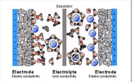
Electrochemical capacitors are devices with a specific capacity of the order of F/g or F/cm3, extremely high compared to the most common electrostatic capacitors, whose capacity is of the order of magnitude of pico, nano or micro Farad for mass or volume units. For this reason, these are called “supercapacitors”. It is commonly referred to supercapacitors with the acronym EDLC (electric double layer capacitor) to highlight the specific feature of supercapacitors, in other words the property of creating a double layer of charge separation within the dielectric. The electrochemical capacitor, as seen in the figure 1.7, is characterized by a construction very similar to that of a battery. It has substantially two electrodes, and a permeable ion separator, placed among the electrodes, which contains the electrolyte.
Figure 1.8: Elemental schematisation of a supercapacitor that emphasizes the mobility of the electrolytic ions, surrounded by solvent, in this case water.
26 Porous electrodes are immersed in an electrolytic solution. Applying a small potential difference to the electrode leads to a charge separation process induced by the presence of an electric field. The area where these charges are concentred is also called double layer, right from where the supercapacitors are called “double layer”. Electrochemical capacitors thus store energy in the double layer, also referred to as Helmoholtz’s layer, which is formed at the electro-electrolyte interface. Here, positively or negatively charged ions accumulate at the electrode-electrolyte interface and are compensated by electrons located on the surface of the electrode. The thickness of this layer depends on the concentration of the electrolyte and the size of the ions. Typically, we have thicknesses of the order of 2 – 10 Å. (76) The electrodes are designed to form a high surface and are made of porous material having pores of the diameter nanometer order to maximize the surface of the double layer.
The supercapacitors are equipped with a high specific capacity thanks to the reduced intermolecular distance between the opposite electrical charge points on the electrolyte-electrode interface, and to the high surface area of the electrolyte-electrode realized through the deposition of carbon with a nanomolecular structure. In addition to the capacity resulting from the separation of charges that is obtained in the double layer there is also a contribution from reactions that can occur on the surface of the coal. Such reactions give rise to an additional accumulation of electricity. In the double layer supercapacitor it has been observed that the principle of operation is mainly based on the separation of charges due to the application of a potential difference between the two electrodes; electrons between electrodes and electrolyte are therefore not transferred.
Pseudo-capacitors
Pseudo-capacitors are hybrids between a battery and a double-layer electric capacitor (EDLC). Due to this configuration, we can leverage the bigger storage capacity of a battery combined with the rapid release of energy of an EDLC. In a supercapacitor one of the two carbon electrodes is replaced by conductive polymers or metal oxides, this involves two different electrodes charging mechanism: the classic double layer electrode and a combination of reactions on the modified one. This combination produces a charge transfer that is dependent on the applied potential, so the device behaves like a normal condenser.
27
Figure 1.8: Basic scheme for (a) doble – layer capacitor (EDLC), (b) a pseudo-capacitor with MnO2 base,
(c) a lithium ion battery. All devices have an active material (carbon, MnO2, LiCoO2), current collector,
28
Chapter 2: Motivation
The main purpose of this thesis was to test the various protocols developed on different substrates and compare them to see which one has the best performance, even in terms of energy storage capabilities.
This thesis work regards studies on copper hexacyanoferrate (CuHCF), one of the most important analogies of the Prussian Blues, with the aim to test the “two-step” electrochemical deposition method: metallic deposition of Cu and anodizing in the presence of [Fe(CN)6]3. The method brings with it some advantages, including the short
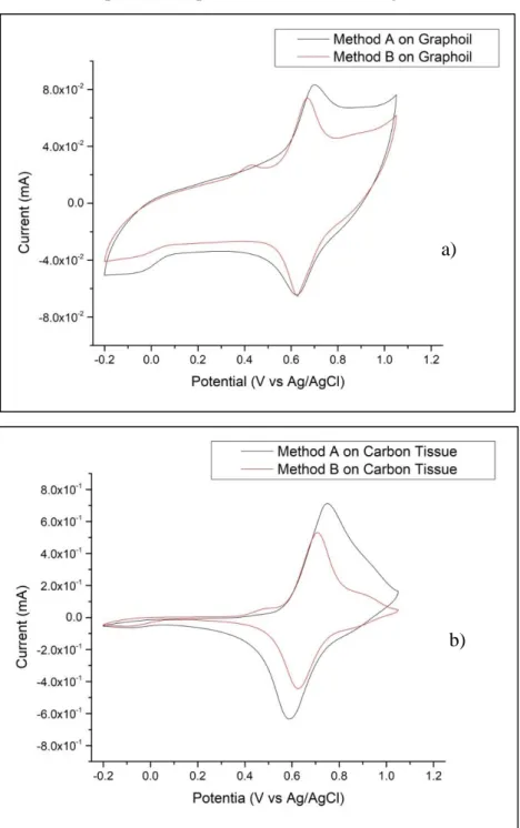
duration of the steeps and the high ratio of deposited material and depositing time. The “one step” methods have the advantage of being able to check the thickness of the film but the synthesis process takes grater time than the “two-step” method. This justifies the interest in deepening and in the improvement of the “two-step” method as an alternative method. Two distinct synthesis protocols, method A and method B, were used during the work and their reproducibility was checked. These two methods lead to obtain different characteristic cyclovoltamograms. Diversity in the form of these traces indicates that the products obtained contain structural differences.
Another goal of this work was the electrochemical synthesis of Co/Al and Co/Fe double layer hydroxides on supports of different nature, with the aim of studying its electrochemical proprieties and in particular the specific capacity for their possible use as supercapacitors. Various tests have been conducted for each support to demonstrate on which the best deposition can be obtained and also the LDH mass obtained for electrosynthesis was evaluated. By varying the deposition time, the correlation between LDH and deposition time was studied.
As far as hair is concerned the purpose of this preparation is to obtain porous carbon from biomass, in this case hair that is a renewable source, and that has become more and more attractive for its abundance, low cost, easy accessibility and environmental friendliness compared with other carbonaceous precursors.
29
Chapter 3: Experimental Part
3.1
Cleaning of electrode surface
Usually research activities involving electrochemical deposition tests are made on electrodes with a low capacitive current and reusable, as carbonaceous materials and metals such as gold, silver and platinum. There is a need to bring the surface back to the same initial condition and every type of material needs a pretreatment protocol. The cleaning treatment has the purpose of erasing the possible traces of previous uses and providing to the external surface a renovated microstructure. There is the possibility to use a conductive substrate that can be hardly reused or there is no need of a pretreatment, such as graphite sheet.
3.1.1 Graphite Sheets
The samples are obtained by cutting rectangles from a A4 graphite sheet having a width of 5 mm and a sufficient height to allow the application of a scotch layer and leave sufficient space to attach the sample to the instrument with a crocodile. The layer of scotch serves to delimit the surface and ensure the reproducibility of the measurements, creating a square with a side of 5 mm. Regarding the cleaning treatment, the graphite sheet has been left to soak in ethanol for about 10 minute. The graphite sheets were provided by VED.
3.1.2 Carbon Cloth, Carbon Paper and Nickel foam
Even in this case the samples are obtained by cutting rectangles having a sufficient height to allow the application of a scotch layer and leave sufficient space to attach the sample to the instrument with a crocodile. The layer of scotch serves to delimit the surface and ensure the reproducibility of the measurements, creating a square with a side of 5 mm. No cleaning treatment was carried out. The carbon cloth and carbon toray paper were provided by Quintech, while the nickel foam was provided by Xiamen Tob New Energy Technology Co.
3.1.3 Glassy Carbon Electrode (GCE)
The use of a glassy carbon electrode not damaged and in good condition is recommended. The cleaning process is done by removing the visible naked eye deposit abrading on 0.05 mm alumina powder (Al2O3) damped on the polishing cloth. The chafe act is executed by
30
3.2
Materials, substances and instrumentation
The following tables show the tools and reagents used to carry out the tests described in the previous paragraphs.
Chemical formula Manufacturer Hexayanoferrate
of iron (III), or ferricyanide
K3Fe(CN)6 Riedel de Haen
Sulphate of copper (II)pentahydrate
CuSO4 * 5H2O Carlo Erba
Potassium
sulphate K2SO4 Sigma Aldrich
Potassium
nitrate KNO3 Sigma Aldrich
Sodium nitrate NaNO3 Sigma Aldrich
Cobalt nitrate
hexaydrate Co(NO3)2 * 6H2O Sigma Aldrich
Aluminium nitrate nonahydrate
Al(NO3)3 * 9H2O Sigma Aldrich
Iron nitrate
nonahydrate Fe(NO3)3 * 9H2O Riedel de Haen
Potassium
hydroxide KOH Sigma Aldrich Zinc nitrate
hexaydrate Zn(NO3)2 * 6H2O Sigma Aldrich
Features Manufacturer Reference Electrode Ag/AgCl CH Instruments, Inc
Counter Electrode Platinum Wire
Potentiostat BioLogic VSP
Horizontal tubular
furnace Temperature control
Energon HLT-40-0/12, H1269
Porosity Analyser Micromeritics ASAP 2020
Cycler MTI BST8
SEM Quanta 650 FEG
XRD Bruker-AXS, model D8
31
3.3
Copper Hexacyanoferrate
Cronoamperometry and cyclic voltammetry (CV) have been used for the electrodeposition and electrochemical characterization processes.
3.3.1 Deposition of metallic Cu and anodization in presence of ferricyanide ion
Medium potentials and long time of application (Method A)
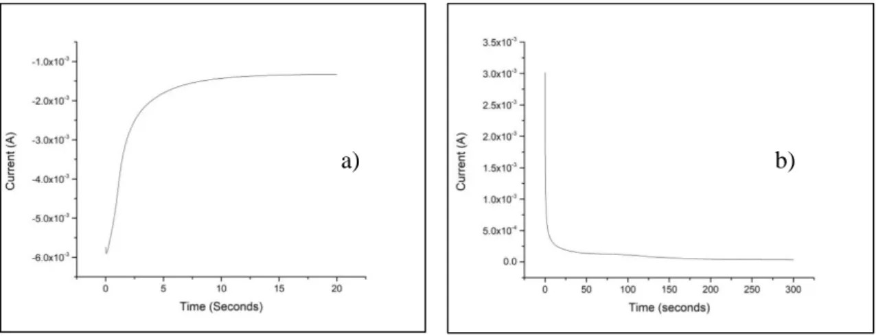
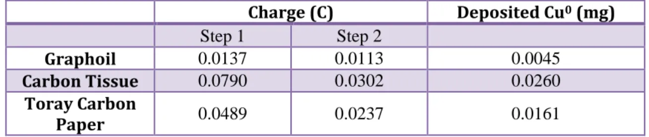
o 1° step Deposition of copper metal film: In this step a solution of CuSO4 0.05M and K2SO4 0.05M. Once assembled the equipment of
counter electrode, reference electrode and working electrode, the deposition was carried out through cronoamperometry applying a potential of -0.80 V for 20 seconds.
o 2° step Dissolution of copper film and subsequent precipitation of
the low soluble salt (CuHCF) on the electrode surface: Once the
electrodes have been rinsed are now immersed in a solution of K3Fe(CN)6 1 mM and K2SO4 0.25 M. using the cronoamperometry
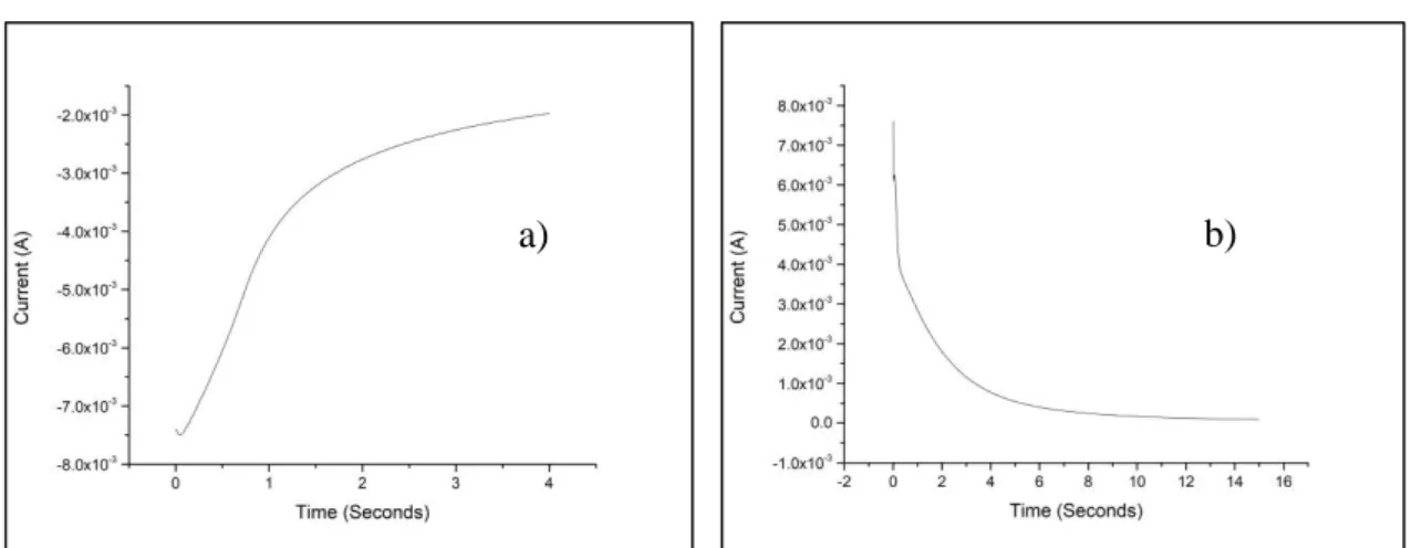
applying a potential of 0.6 V for 300 seconds and we can observe a sharp drop in current due to the formation of CuHCF on the surface electrode. After an average of 40 seconds it is normal to observe precipitation in bulk represented by a trail that moves from the electrode to the solution.
Extreme potential and short time of deposition (Method B)
o 1° step Deposition of copper metal film: Also for this passage a solution of CuSO4 0.05 M in KSO2 0.05 M is used. Once assembled
the equipment of counter electrode, reference electrode and working electrode, the deposition was carried out through cronoamperometry applying a potential of -1 V for 4 seconds.
o 2° step Dissolution of copper film and subsequent precipitation of
the low soluble salt (CuHCF) on the electrode surface: Once the
electrodes have been rinsed are now immersed in a solution of K3Fe(CN)6 1 mM and K2SO4 0.25 M. using the cronoamperometry
applying a potential of 1 V for 15 seconds and we can observe a sharp drop in current due to the formation of CuHCF on the surface electrode.
32
3.3.2 Electrochemical Characterization
The characterization of CuHCF films was performed by cyclic voltammetry in solution of KNO3 0.1 M with the same instrumental configuration used for the deposition, cycling the
potential between -0.2 V and 1.05 V. Normally 10 voltammetric cycles at the scan rate of 10 mV/s and 100 mV/s and 3 voltammetric cycles at the scan rate of 1 mV/s were performed. All operations were performed at a room temperature.
3.4
Nickel Hexacyanoferrate
Nickel hexacyanoferrate electrosynthesis was performed in a three electrode cell by applying a constant potential.
The three electrodes were immersed in a glass cell containing a solution of K2Fe(CN)6 5
mM and KNO3 0.1 M for 300 seconds, subsequently applying a potential oh 1.0 V for
another 300 seconds. The thus deposited NiHCF was then characterized by cyclic voltammetry in NaNO3 1.0 M, KNO3 0.1 M, Al(NO3)3 * 9H2O 0,1 M or Zn(NO3)2 * 6H2O
0,1 M. At first a constant potential of 0.25 V was applied at the electrode for 120 seconds. After this a cyclic voltammetry was conducted at a scan rate of 50 mV/s in a potential window between -0.1 V and 0.8 V. All operations were performed at a room temperature.
3.5
Layered double hydroxides (LDH)
All electrochemical tests were performed using a single cell with three electrodes: reference electrode, counter electrode and working electrode. These tests were first depositing a Co/Al LDH and a Co/Fe LDH, according to the electrodeposition procedures that will be described below. All operations were performed at a room temperature.
3.5.1 Co/Al LDH
The three electrodes were introduced into a Co(NO3)2 * 6H2O and Al(NO3)3 * 9H2O
solution with a total concentration of 0.03M and in 3:1 ratio to allow deposition by applying a potential of -1.15V for 30 seconds. Characterization by cyclic voltammetry was conducted in a KOH 1M solution between 0V and 0.5V by running 10 cycles at a scan rate of 10 mV/s and 50 mV/s and 2 cycles at a scan rate of 1 mV/s.
3.5.2 Co/Fe LDH
The three electrodes were introduced into a Co(NO3)2 * 6H2O and Fe(NO3)3 * 9H2O
33 applying a potential of -1.15V for 30 seconds. Characterization by cyclic voltammetry was conducted in a KOH 1M solution between -0.4V and 0.2V by running 10 cycles at a scan rate of 10 mV/s and 50 mV/s and 2 cycles at a scan rate of 1 mV/s.
3.6
Hair
The hair was washed with soap and dried. Once dried they were placed in ceramic bowls and introduced into the oven. Here, a stabilization treatment has taken place up to a temperature of 300 °C in presence of oxygen with an increase in temperature of 1 °C per minute. Once reached the temperature of 300 °C this was maintained for 1 hour, after which the temperature was lowered to 20 °C with a ramp of 5 °C per minute. Small amounts of stabilized hair mixture and KOH were prepared in different ratios ( 1 to 2, 1 to 1.25, 1 to 1, 1 to 0.5, 1 to 0.25 and 1 to 0). KOH immersing leads to a homogeneous mixture of them, and KOH oxidatively reacts with carbon at high temperature to generate H2, CO2 and CO gas and thus produce the pores. The activation mechanism of KOH is as below
(77): 6𝐾𝑂𝐻 + 2𝐶 → 2𝐾 + 3𝐻2 + 2𝐾2𝐶𝑂3 𝐾2𝐶𝑂3 → 𝐾2𝑂 + 𝐶𝑂2 𝐶𝑂2+ 𝐶 → 2𝐶𝑂 𝐾2𝐶𝑂3+ 2𝐶 → 2𝐾 + 3𝐶𝑂 𝐾2𝑂 + 𝐶 → 2𝐾 + 𝐶𝑂
After mixing well in a mortar, they were reintroduced into the oven and subjected to activation treatment that bring to a temperature of 900 °C with an increase ramp of 3 °C per minute, keeping it for 3 hours and then bring it back to 20 °C with a ramp of 5 °C per minute, all in the presence of nitrogen with a flow of 28/30 bubbles every quarter of a minute. Taken out of the oven before it was neutralized with a solution of HCl 2M until it reached a pH of about 6, after which it was washed twice with water using a centrifuge. On the samples thus obtained were made nitrogen absorption isotherms to obtain information on porosity and other parameters such as volume and microporous area.
3.6.1 Adsorption isotherms
It is very important to quantify the surface of porous carbons in order to carry out a comparative study between structure and proprieties. The study of the microporous and macroporous structure of the material with the synthesis parameters and the storage capacity of the material. This textural analysis was carried out by adsorption – desorption
34 isotherms measurements of N2 at -196°C using a Micromeritics ASAP 2020 porosity
analyser. To obtain these data, a protocol of preparation and measurements was followed which involves several steps and it is described below:
Degassing: before introducing the sample into the equipment is necessary to ensure the pores don’t contain air, moisture or other volatile components derived from the synthesis. The sample, between 50 and 100 mg, are collocated in a glass holder, which is closed using a plug with an O – ring to seal. It is placed in the degassing port and kept in a vacuum for 3 hours, heating with a blanket at 180°C. Although mass losses in degasification were not large, the holder with the degassed sample was always weight and the resulting mass is taken into account for subsequent calculations. Like all the carbons developed an important microporosity in some cases was required the study of adsorption in the area of low relative pressures. For this, another degassing at a much larger vacuum (0.1 m) for 3 hours.
Analysis: After having the degassed sample, it is placed in the measurement port and the equipment begins to measure according to the program previously assigned to it. In our case points at relative pressures were selected (pressure respect to the pressure of condensation at the temperature at which measurements are conducted) between 0.005 and 1 covering the whole area of mesopores and macropores where the nitrogen is capable to condensing. When the analysis was performed at low relative pressure (below 0.005) you have to select manually the nitrogen dose for each point.
Surface of mesoporous: the most commonly used methods for obtaining mesoporous surface parameters in porous material are applied on the adsorption – desorption isotherm. Some modifications were made to the Langmuir kinetic model to evaluate the external area of material, until 1935, when Brunauer and Emmett developed the model BET (Brunauer – Emmett – Teller) (78). Now the BET model is one of the most used models for the determination of the surface area of adsorbents, catalyst and porous materials, although the underlying model is not very realistic since it is based on several assumptions.
Surface of microporous: a first value of the microporosity parameters was already obtained with the adsorption – desorption isotherms, but to obtain information on the microporous filling there is the need to measure at lower relative pressures because when the interaction of the pore with the adsorbent is strong the adsorption
35 is produced at lower relative pressures. The obtaining of the textural parameters is carried out with mathematical analysis of the isotherms adsorption that uses models based on different theoretical foundations. For data processing the most used model is the Dubinin – Radushkevich (79) which is semi – empirical, since it doesn’t underlie any theory but assumes some of the assumptions that appear in other theoretical models, part of the idea that the total occupation of the micropores doesn’t occur after the formation of multi-layered, as occurs with mesopores.
Calculation of the pore distribution: the BJH model was used for the calculation of the mean mesopore size, the volume of mesopore and the mesopore distributions of both adsorption and desorption were calculate with the BJH method.
3.7
Electrochemical techniques used
3.7.1 Chronoamperometry
Chronoamperometry is a potentiostatic electrochemical technique with which the current passing through an electrode is measured, depending on time. Chronoamperometry is particularly useful in all cases where the redox process that we want to monitor is governed by the diffusion occurring in the region at a d distance from the electrode’s surface. It is necessary that the analytical solution, that contains the redox pair, is not subject to agitation and the temperature must be kept constant.
When the potential applied to the working electrode is the same of the equilibrium one of the redox pair (EWE = Eeq), there is no current passage, because the two reactions, of
oxidation and reduction, continue at the same speed. If the potential that we apply to the working electrode is different from the equilibrium one, there is a progressive increase of the current that can be due to the oxidation (anodic current, ia) and reduction (cathodic
current, ic) of the redox pair present in the solution. In conclusion, applying a suitable
potential and assuming that in the solution is present the specie Aox, is possible to register
a discharge current. Applying a potential different from the one of equilibrium the concentration of Aox next to the electrode surface decrease fast, and also the faradic current.
After the Aox species near the electrode has been consumed, a concentration gradient is
created and it causes a spontaneous diffusion of the species towards the electrode. Since the solution is quiet and the reduction continues the Aox species have to spread from far
distances and this causes a constant decrease in current from the starting value to a constant value. The current associated to the process decays as described by Cottrell’s law: