POLITECNICO DIMILANO
DEIB
DOCTORALPROGRAMME ININFORMATIONTECHNOLOGY
C-B
ASED
H
IGH
L
EVEL
S
YNTHESIS OF
P
ARALLEL
A
PPLICATIONS
T
ARGETING
A
DAPTIVE
H
ARDWARE
C
OMPONENTS
Doctoral Dissertation of:
Vito Giovanni Castellana
Supervisor:
Prof. Fabrizio Ferrandi
Tutor:
Prof. Donatella Sciuto
The Chair of the Doctoral Program:
Prof. Carlo Ettore Fiorini
Acknowledgments
Hey I know it’s late, but we can make it if we run. The boss wrote these words, which more or less summarize my last few years. This is what I did: I ran. And this is what a PhD student is supposed to do, no matter how late it is, no matter how far the objective, you have to move forward trying to reach it. But sometimes, even for just a few seconds, it’s good to take a look behind. If I do that, I realize how far these three years took me. The journey has been amazing though. So I just want to say thank you to all the traveling companion who made this journey so special, and who supported me while trying to reach my goals.
Il mio primo ringraziamento va ad Antonino. A tuo modo hai saputo amplificare la mia voglia di fare, di non arrendermi, e di raggiungere gli obiettivi, anche quelli più improbabili. E sei stato oltre che un buon men-tore, un grande amico.
Grazie a tutti gli amici e parenti, per essere sempre riusciti a farmi avvertire la vostra prensenza e il vostro affetto.
Grazie a tutti coloro che mi hanno aiutato a sentirmi un pò a casa, anche quando a migliaia di chilometri di distanza.
Grazie a Fabrizio. Grazie per avermi insegnato a domare le idee, e solo dopo a seguirle. Grazie per aver reso più acuto e critico il mio giudizio, e più profonda e ampia la mia preparazione. Per avermi bacchettato quando ho sbagliato, e per avermi dato fiducia. Grazie per avermi trasmesso la tua passione per quel che facciamo.
Grazie a Marco, molto più che un semplice amico. Hai condiviso con me sogni e passioni, gioie e delusioni, mi hai offerto il tuo supporto quando ne
ho avuto bisogno, sei stato la chitarra che ha supportato la mia voce. E non mi riferisco alle (tante) volte in cui ci siamo improvvisati musicisti.. Grazie a Michele, il miglior fratello che si possa desiderare. Grazie per la tua discreta attenzione, per il tuo affetto, per aver saputo spesso essere an-che amico e complice.
E infine, il GRAZIE più grande va ai miei genitori. Come non dirò mai abbastanza, ogni mio successo è prima di tutto il vostro. Senza il vostro amore, il vostro supporto e la vostra stima, ogni piccolo traguardo che ho raggiunto sarebbe ancora lontano.
Thank you.
Abstract
T
HE EVER INCREASING COMPLEXITY of embedded systems isdriv-ing design methodologies towards the use of abstractions higher than the Register Transfer Level (RTL). In this scenario, High Level Synthesis (HLS) plays a significant role by enabling the automatic genera-tion of custom hardware accelerators starting from high level descripgenera-tions (e.g., C code). Typical HLS tools exploit parallelism mostly at the Instruc-tion Level (ILP). They statically schedule the input specificaInstruc-tions, and build centralized Finite Stat Machine (FSM) controllers. However, the majority of applications have limited ILP and, usually, centralized approaches do not efficiently exploit coarser granularities, because FSMs are inherently serial. Novel HLS approaches are now looking at exploiting coarser parallelism, such as Task Level Parallelism (TLP). Early works in this direction adopted particular specification languages such as Petri nets or process networks, reducing their applicability and effectiveness in HLS. This work presents novel HLS methodologies for the efficient synthesis of C-based parallel specifications. In order to overcome the limitations of the FSM model, a parallel controller design is proposed, which allows multiple flows to run concurrently, and offers natural support for variable latency operations, such as memory accesses. The adaptive controller is composed of a set of interacting modules that independently manage the execution of an opera-tion or a task. These modules check dependencies and resource constraints at runtime, allowing as soon as possible execution without the need of a static scheduling. The absence of a statically determined execution order has required the definition of novel synthesis algorithms, since most of the
common HLS techniques require the definition of an operation schedule. The proposed algorithms have allowed the design and actual implemen-tation of a complete HLS framework. The flow features automatic paral-lelism identification and exploitation, at different granularities. An analysis step, interfacing with a software compiler, processes the input specifica-tion and identifies concurrent operaspecifica-tions or tasks. Their parallel execuspecifica-tion is then enabled by the parallel controller architecture. Experimental re-sults confirm the potentiality of the approach, reporting encouraging per-formance improvements against typical techniques, on a set of common HLS benchmarks. Nevertheless, the interaction with software compilers, while profitable for the optimization of the input code, may represent a lim-itation in parallelism explolim-itation: compilation techniques are often over-conservative, and in the presence of memory operations accessing shared resources, force serialization. To overcome this issue, this work consid-ers the adoption of parallel programming paradigms, based on the insertion of pragma annotations in the source code. Annotations, such as OpenMP pragmas, directly expose TLP, and enable a more accurate dependences analysis. However, also in these settings, the concurrent access to shared memories among tasks, common in parallel applications, still represents a bottleneck for performance improvement. In addition, it requires concur-rency and synchronization management to ensure correct execution. This work deals with such challenges through the definition of efficient memory controllers, which support distributed and multi-ported memories and allow concurrent access to the memory resources while managing concurrency and synchronization. Concurrency is managed avoiding, at runtime, multi-ple operations to target the same memory location. Synchronization is man-aged providing support for atomic memory operations, commonly adopted in parallel programming. These techniques have been evaluated on several parallel applications, instrumented through OpenMP pragmas, demonstrat-ing their effectiveness: experimental results show valuable speed-ups, often close to linearity with respect to the degree of available parallelism.
Contents
1 Introduction 7 1.1 Main Contributions . . . 9 1.2 Dissemination of Results . . . 10 1.3 Thesis Organization . . . 11 2 Background 13 2.1 Introduction to High-Level Synthesis . . . 142.2 The Finite State Machine with Data-Path Model . . . 15
2.2.1 Data-Path . . . 15
2.2.2 Finite State Machine . . . 17
2.3 Typical High Level Synthesis Flows . . . 19
2.3.1 Front End . . . 20
2.3.2 Synthesis . . . 21
2.3.3 Back-end . . . 26
2.4 Bambu: A Free Framework for the High-Level Synthesis of Complex Applications . . . 26 2.4.1 Front-end . . . 28 2.4.2 Synthesis . . . 28 2.4.3 Back-end . . . 31 2.5 Conclutions . . . 31 3 Related Work 33 3.1 HLS Design Methodologies Characterization . . . 34
Contents 3.3 First HLS Generation . . . 36 3.3.1 Architectural Models . . . 38 3.4 Second HLS Generation . . . 39 3.4.1 Architectural Models . . . 40 3.5 Third HLS Generation . . . 48
3.5.1 HLS and EDA Industry . . . 51
3.5.2 Architectural Models . . . 54
3.6 Conclusions . . . 56
4 The Parallel Controller Architecture 59 4.1 Motivation . . . 60
4.2 Related Work . . . 63
4.3 The Parallel Controller Architecture . . . 65
4.4 Adaptive Behavior . . . 71
4.5 Conclusions . . . 72
5 High Level Synthesis of Adaptive Hardware Components 73 5.1 Proposed High Level Synthesis Flow . . . 74
5.2 Compilation and IR Generation . . . 76
5.2.1 Extended Program Dependence Graph . . . 77
5.2.2 Activating Conditions Computation . . . 78
5.3 Module Binding . . . 79
5.4 Liveness Analysis and Register Binding . . . 79
5.4.1 Preliminary Notions and Definitions . . . 81
5.4.2 Schedule-Independent Liveness Analysis . . . 82
5.4.3 Conflict Graph Creation . . . 85
5.4.4 Algorithm Evaluation . . . 86
5.5 Controller Generation . . . 89
5.6 Support for Complex Behaviors . . . 90
5.7 Implementation Details: Integration in the Bambu Framework 91 5.8 Experimental Evaluation . . . 92
5.9 Conclusions . . . 94
6 The Memory Interface Controller 97 6.1 Motivation . . . 99
6.2 Related Work . . . 102
6.3 Accelerating Memory Intensive and Irregular Applications . 103 6.4 Accelerator Design Template . . . 106
6.4.1 Exploitation of the Parallel Controller Architecture . . 107
6.5 Memory Interface Controller Design . . . 108
6.6 Experimental Evaluation . . . 111
Contents
6.7 Conclusions . . . 114
7 Support for Annotated Parallel Specifications 115 7.1 Motivation . . . 117
7.2 Related Work . . . 118
7.3 Refined High Level Synthesis Flow . . . 119
7.3.1 Front-end . . . 123
7.3.2 Flow Selection . . . 124
7.3.3 Synthesis . . . 124
7.3.4 FSM-based synthesis flow . . . 125
7.3.5 Parallel Controller synthesis flow . . . 126
7.4 The Distributed Memory Interface . . . 126
7.5 Experimental Evaluation . . . 130 7.5.1 Performance Evaluation . . . 132 7.5.2 Area Evaluation . . . 134 7.6 Conclusions . . . 137 8 Conclusions 139 8.1 Novel Contributions . . . 140
8.1.1 The Parallel Controller Design . . . 140
8.1.2 High Level Synthesis of Adaptive Hardware Compo-nents . . . 140
8.1.3 Memory Interface Controller . . . 141
8.1.4 Support for Annotated Parallel Specifications . . . 141
8.2 Further Development . . . 142
8.3 Future Research Directions . . . 143
List of Figures
2.1 Typical Architecture composed of a Finite State Machine
(FSM) and a Data-path. . . 16
2.2 Typical HLS flow. . . 20
2.3 Pseudo-code, DFG and scheduled DFG of a program that computes the average of 4 numbers. . . 23
2.4 Panda framework schematic overview. . . 26
2.5 PandA analysis flow. . . 27
2.6 Bambu Synthesis Flow. . . 29
3.1 Main Features Characterizing Design Methodologies in HLS. 35 3.2 Standard Structure of a Centralized FSM. . . 38
3.3 Parallel Decomposition of a Finite State Machine. . . 41
3.4 Cascade Decomposition of a Finite State Machine. . . 42
3.5 Generalized Decomposition of a Finite State Machine. . . . 42
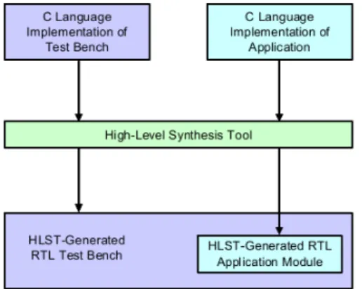
3.6 Tipical HLS tools output including RTL and RTL test benches. 50 3.7 EDA revenue history, 1996 - present. . . 52
3.8 Maximum frame rate achieved for a video application on a DSP processor and an FPGA plus HLS tools. . . 53
3.9 FPGA resource utilization on a wireless receiver, implemented using HLS tools versus hand-written RTL code. . . 53
3.10 Example of Petri Net Specification of a Controller. . . 55
4.1 Example C specification. . . 61
List of Figures
4.3 Product STG for function call_loops; calls are represented by produced values. . . 63 4.4 N-inputs join module behavior: statei is high if the i-th
to-ken signal inihas already been collected. . . 66
4.5 2-inputs join module RTL schematic representation. . . 66 4.6 N-inputs Resource Manager behavior: requests are ordered
according to their priority. . . 67 4.7 3-inputs Resource Manager RTL schematic representation. . 67 4.8 Distributed Controller Modules: single-cycle(a), multi-cycle(b)
and unbounded operations(c) Execution Managers (EM). . . 68 4.9 Dependence graph for function call_loops, annotated with
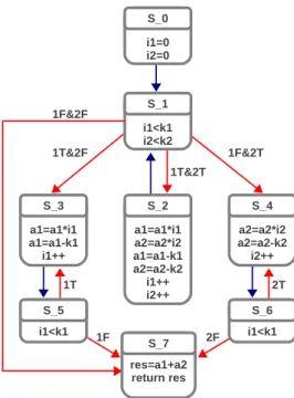
Activating Conditions. . . 69 4.10 Distributed controller architecture for function call_loops. . 69 4.11 Runtime behavior of adaptive controller: execution trace of
function loops with k1 = k2 = 2, under resource constraint (one instance available for each kind of functional unit). . . 69 4.12 Example specification (a) and corresponding parallel
con-troller implementation. Operations 3, 4 and 5 share FU C, operations 6 and 7 share FU D. . . 70 4.13 Runtime schedules when considering dynamic variations on
FU latencies. Assumed priority for RMs: op3<op4<op5; op6<op7. . . 71 5.1 Proposed High Level Synthesis flow. . . 75 5.2 Example C specification, after the compilation step. . . 76 5.3 Extended program Dependence Graph for function call loops,
annotated with Activating Conditions. Blue edges denote data dependences, red edges control dependences, green edges backward control flow dependes, purple edges forward con-trol flow dependencies. . . 77 5.4 Scheduled CDFG (a), runtime schedule in the case of
mis-prediction for SFU 2 (b) and runtime schedule in the case of misprediction for SFU 2, without the resource constraint between nodes 2 and 4. . . 80 5.5 Example Dependencies Graph. . . 83 5.6 Liveness analysis results solving standard DF equations (a),
livepsets(b), for the example DG in Figure 5.5. . . 83
5.7 Proposed liveness analysis results for the example DG in Figure 5.5. . . 85
List of Figures
5.8 Conflict Graph obtained for the previous example, keeping live_out and livep sets disjoint (a) and Conflict Graph
ob-tained unifying live_out and livepsets (b). . . 86
6.1 Schematic representation of Convey HC-1 platform. . . 100
6.2 Application Template . . . 103
6.3 Queue-based BFS implementation . . . 104
6.4 Parallelized Application Template . . . 105
6.5 Accelerator design template schematic representation. . . . 106
6.6 Top Level Memory Interface Controller Structure. . . 108
6.7 Memory Interface Controller schematic representation. . . . 109
7.1 Application template . . . 120
7.2 Application template for Partial Unrolling . . . 120
7.3 Proposed High Level Synthesis Flow. . . 121
7.4 Example annotated parallel specification . . . 122
7.5 Intermediate code produced during the compilation process. 123 7.6 EPDG with structural dependencies. . . 125
7.7 EPDG after dependences pruning. . . 125
7.8 Memory interface structure. . . 127
7.9 Example Call Graph (a) and associated memory interface structure (b). The framed nodes in the CG are associated with functions that directly perform memory accesses; ar-biters include RMs and UNBD modules. . . 128 7.10 Memory interface for distributed and multi ported memories. 131
List of Tables
2.1 Typical HLS inputs and outputs . . . 14 2.2 External synthesis and simulation tools supported by the Bambu
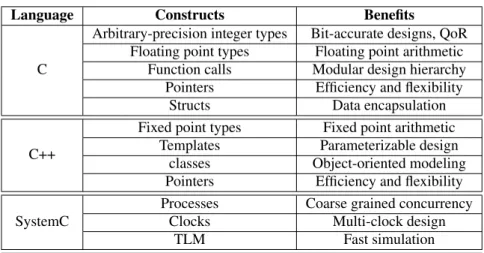
framework. . . 31 3.1 Regular Expression DAG Symbols. . . 47 3.2 Useful high-level languages features for C-based design and
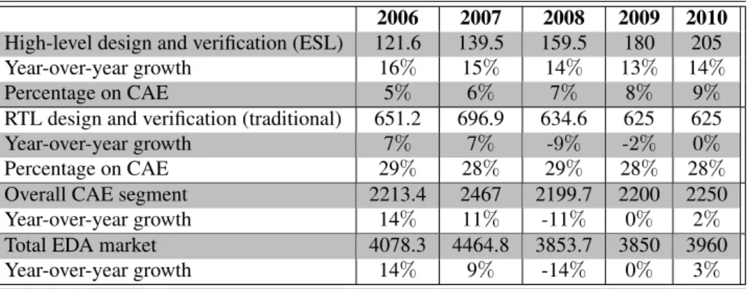
synthesis. . . 49 3.3 EDA segments revenue analysis ($ MILLIONS). Source: EDAC
MSS Statistics Report and Desaisive Technology Research analysis. . . 52 5.1 High Level Synthesis results: Register Binding. . . 87 5.2 Design Compiler Synthesis Results: comparison against unique
binding. . . 88 5.3 Design Compiler Synthesis Results: Comparison Against
Vertex Coloring. . . 88 5.4 Execution latencies (number of clock cycles) targeting
adap-tive and FSM-based accelerators. . . 92 5.5 Synthesis results: number of required Flip Flop(FF), LUT
and FF/LUT pairs targeting adaptive and FSM-based accel-erators. . . 93 6.1 Resource requirements and complexity for a MIC managing
N input operations towards M memory banks. . . 110 6.2 Area evaluation of Memory Interface Controllers. . . 111
List of Tables
6.3 Simulation results; input graph: 5000 nodes, average degree: 10. . . 112 6.4 Simulation results; input graph: 5000 nodes, average degree:
20. . . 113 6.5 Simulation results; input graph: 5000 nodes, average degree:
30. . . 113 6.6 Area evaluation of the generated designs. . . 114 7.1 Simulation results: execution latencies in terms of clock
cy-cles, and speedups for the proposed flow, interfacing single and multi ported memories (4 channels). All the designs tar-get an operating frequency of 100MHz. . . 133 7.2 Synthesis results: number of Flip Flop (FF) registers and
Logic Elements (LEs) required by the generated designs. Area overhead ratios consider the number of required LEs. . 135
CHAPTER
1
Introduction
Since the inception of information technology, the synthesis of digital cir-cuits has been a main concern for researchers and scientific community. Over the years, the proposed design methodologies have been forced to move to higher abstraction levels due to the constant improvements in sil-icon technology and to the increasing complexity of applications and ar-chitectures. Such factors, since early ’70s, made more inadequate lower abstraction level methodologies such as Logic-level or Physic-level syn-thesis, and led to their overcome in favor of High-Level Synthesis (HLS). Over the years HLS has been able to capture and renew the interests of the research community, even if in the past its adoption in industry has often resulted in failures. However current systems complexity is quickly turning HLS from an undeniably promising idea to an actual need. For example, in [186] the authors report a study from NEC showing that a 1M-gate de-sign typically requires about 300k lines of RTL code, which are difficult to be handled by a human designer. Adopting high level description lan-guages, such as C/C++, the code density dramatically reduces (up to 10X): behavioral languages can describe 1M-gate designs in 30-40k lines of code. Other reviews reported in literature indicate that working at a higher level of the design hierarchy using high-level synthesis reduces the amount of
Chapter 1. Introduction
code that must be developed by as much as two thirds [128]. Constant improvements in HLS have finally led to the (at least partial) automation of the design process, significantly decreasing the development cost. Fur-thermore, the error rate is reduced by the presence of a proper verification phase. While writing behavioral code is inherently simpler than writing RTL code, separating the design intent from the physical implementation avoids the tedious process of rewriting and retesting code to make archi-tectural changes. This also facilitates the design space exploration process since a good synthesis system produces several RTL implementations for the same specification in a reasonable amount of time, allowing the de-velopers to consider different solutions and trade-offs. Generally, it is re-ported an overall reduction of the design effort, with respect to lower level methodologies, of 50% or more [128]. This characteristics shorten the de-sign cycle, thus increasing the chance for companies of hitting the mar-ket window. Almost four decades of research have resulted in impressive improvements in HLS methodologies: modern frameworks support C-like programs as input specification, providing a wide language coverage; they integrate engines for quick and efficient design space exploration; they are able to exploit modern reconfigurable platforms, and directly interface with the logic synthesis tools; finally, and most important of all, they provide good Quality of Results (QoR), especially for specific domains. However there are still several aspects which need further investigation, and several opportunities for improvement, which motivate the work described by this thesis. For example, most of the proposed design methodologies targeted the same architectural model as a result of synthesis, i.e. the Finite State Machine with Datapath (FSMD) model. FSMDs are composed by a data-path, which includes the hardware resources which perform the computa-tion, and a FSM controller, which manages the computation. As detailed in the next chapters, FSMDs are inherently serial: they model execution as a sequence of control steps, thus limiting parallelism exploitation within a single execution flow. Architectural alternatives exist, but they have not been comprehensively explored yet. This work investigates one of such al-ternatives, i.e. parallel controllers. Parallel controllers are able to manage multiple execution flows concurrently, thus overcoming one of the main limitation of the FSM-based paradigms. A parallel controller design is pro-posed, suitable for HLS. Such model allows the synthesis of adaptive ac-celerators featuring dynamic scheduling. Typical FSMDs are built reflect-ing a statically computed schedule; in the proposed architecture instead, execution is managed through a set of communicating elements, which es-tablishes directly at runtime if an operation can be executed. The absence
1.1. Main Contributions
of a pre-computed execution ordering has required the definition of novel algorithms for most of the steps composing the synthesis process. Typical approaches in fact, are based on the definition of a static schedule, thus resulting not applicable. The designed synthesis flow has been automated through the definition and actual implementation of a complete C-based HLS tool. Compared with existing approaches, the generated adaptive com-ponents provide unique benefits. Among them, the most relevant are the efficient management of variable latency operations, poorly supported by statically scheduled FSMDs, and the support for coarse grained parallelism exploitation. Coarse grained parallelism mostly occurs in the form of Task Level Parallelism (TLP): however, exploiting and identifying TLP intro-duce several challenges. TLP exploitation is a complex problem: usually tasks share memory resources, and if they are allowed to execute at the same time, concurrency and synchronization between them must be man-aged. TLP identification, instead, is difficult because most of the adopted specification languages are programming languages such as C/C++, which have been designed for serial execution. This work has considered both these aspects. The first one has been addressed through the definition of a Memory Controller Interface (MIC). The MIC is a hardware component which allows fine grained parallelism exploitation on memory accesses, au-tomatically manages concurrency on shared resources, and supports atomic memory operations for synchronization. It has been designed as a custom, parameterizable IP, suitable for easy adoption in both RTL and HLS flows. The second challenge has been considered introducing in the designed flow, support for parallel programming APIs. This allow the input specification to directly expose parallelism, and to take advantage of atomic memory op-erations, supported by the MIC, for tasks synchronization. The resulting HLS flow is then able to efficiently exploit TLP, identified through pragma annotations in the input code. According to the particular characteristics of the specification, it is also able to automatically adopt different synthe-sis approaches: functions characterized by ILP only are synthesized with FSM-based techniques, while code featuring TLP is synthesized targeting the proposed adaptive architectures.
1.1
Main ContributionsThe main contributions of this work may be summarized as follows: • the definition of a parallel controller design, suitable for the HLS of
adaptive hardware components featuring dynamic scheduling: execu-tion is managed through a set of components, interacting through a
Chapter 1. Introduction
lightweight token-based communication schema. Each element es-tablish directly at runtime when an operation can execute;
• the design of novel HLS algorithms for the automated synthesis of the proposed architecture;
• the development of a complete C-based HLS tool, targeting the adap-tive accelerator design;
• the design of hardware components for managing concurrency and synchronization on shared memories, thus providing support for effi-cient TLP exploitation;
• the support for parallel programming APIs, which allow efficient iden-tification of TLP;
• the definition of a modular architecture which couples statically and dynamically scheduled components, to best adapt to the characteris-tics of the input specification;
• the experimental evaluation of each of the techniques proposed in this thesis, comparing them to existing approaches.
1.2
Dissemination of ResultsTechniques and methodologies described in this thesis work have been pre-sented at several international conferences, leading to the publication of the following papers:
1. C. Pilato, V.G. Castellana, S.Lovergine, F. Ferrandi, A Runtime Adap-tive Controller for Supporting Hardware Components with Variable Latency, in Proceedings of NASA/ESA Conference on Adaptive Hard-ware and Systems (AHS-2011), San Diego, California, USA, June 2011
2. V.G. Castellana and F. Ferrandi, Speeding-Up Memory Intensive Ap-plications through Adaptive Hardware Accelerators, in Proceedings of High Performance Computing, Networking, Storage and Analysis, 2012 SuperComputing Companion (SCC), Salt Lake City, Utah, USA, November 2012
3. V.G. Castellana and F. Ferrandi, Scheduling Independent Liveness Anal-ysis for Register Binding in High Level Synthesis, in Proceedings of Design, Automation & Test in Europe Conference & Exhibition (DATE), 2013, Grenoble, France, March 2013
1.3. Thesis Organization
4. V.G. Castellana and F. Ferrandi, Applications Acceleration Through Adaptive Hardware Components, in Proceedings of Parallel and Dis-tributed Processing Symposium Workshops & PhD Forum (IPDPSW), Boston, Massachussets, USA, May 2013
5. V.G. Castellana and F. Ferrandi, An Automated Flow for the High Level Synthesis of Coarse Grained Parallel Applications, in Proceed-ings of International Conference on Field-Programmable Technology (ICFPT) 2013, Kyoto, Japan, December 2013
6. V.G. Castellana, A. Tumeo, F. Ferrandi, An Adaptive Memory Inter-face Controller for Improving Bandwidth Utilization of Hybrid and Reconfigurable Systems, in Proceedings of Design, Automation & Test in Europe Conference & Exhibition (DATE), 2014, Dresden, Ger-many, March 2014
7. V.G. Castellana, A. Tumeo, F. Ferrandi, High Level Synthesis of Mem-ory Bound and Irregular Parallel Applications with Bambu, Interna-tional Workshop on Electronic System-Level Design towards Hetero-geneous Computing, 2014, Dresden, Germany, March 2014
Informal proceedings and other dissemination activities:
• V.G. Castellana, C. Pilato, F. Ferrandi, Accelerating Embedded Sys-tems with C-Based Hardware Synthesis, HiPEAC ACACES-2011, Fi-uggi, Italy, July 2011 [Meeting proceedings, ISBN:978 90 382 17987] • V.G. Castellana, A. Tumeo, F. Ferrandi, A Synthesis Approach for Mapping Irregular Applications on Reconfigurable Architectures, High Performance Computing, Networking, Storage and Analysis, 2013 SuperComputing (SC), Denver, Colorado, USA, November 2013 [Tech-nical Program poster, extended abstract available online]
• V.G. Castellana, F. Ferrandi, C-Based High Level Synthesis of Adap-tive Hardware Components, Design, Automation & Test in Europe Conference & Exhibition (DATE), 2014, Dresden, Germany, March 2014 [PhD forum presentation]
1.3
Thesis OrganizationThe remainder of this thesis is organized as follows: Chapter 2 provides a background for this work, introducing basic concepts and definitions. It
Chapter 1. Introduction
also proposes Bambu as an example of modern HLS tools. The methodolo-gies presented in this thesis have been developed within the Bambu frame-work, and its release version, freely available on-line, has represented a baseline for evaluation. Chapter 3 illustrates related work, tracking the chronological evolution of HLS, and identifying which aspects need fur-ther improvements, thus highlighting the contribution of this work to the state of the art. Chapter 4 introduces the proposed parallel controller ar-chitecture, describing all the designed components, and showing its adap-tive behavior and main offered features through some examples. Chapter 5 describes the complete HLS flow for the automatic generation of the pro-posed architecture, detailing each of the algorithm composing the synthesis process. Chapter 6 presents the Memory Controller Interface, designed to manage concurrency and synchronization for memory intensive specifica-tions. Chapter 7 focuses on TLP identification and exploitation, proposing refinements and improvements to the HLS flow, enabling efficient support of parallel applications instrumented through pragma annotations. Chapter 8 concludes this thesis, identifying opportunities for further improvements and promising future research directions.
CHAPTER
2
Background
This thesis work proposes novel adaptive architecture designs for the syn-thesis of hardware accelerators, together with algorithms for their automatic generation through a High Level Synthesis (HLS) flow. This chapter intro-duces some preliminary concepts and definitions, useful to briefly build a background for this work. As a representative of modern synthesis tools, the Bambu framework is proposed. Bambu is a state of the art HLS tool, producing Verilog implementations of behavioral specifications described through C-code. Methodologies and techniques described in this work, have been implemented customizing and extending this framework, and its release version, freely available on the Internet, has represented a base-line for evaluation. The remainder of this chapter is organized as follows: Section 2.1 introduces the High-Level Synthesis process; Section 2.2 de-scribes the Finite State Machine with Data-path model, which is the most widespread design solution adopted in HLS. Section 2.3 formally char-acterizes a typical HLS flow, which can be coarsely partitioned in three main stages: the Front-end phase (2.3.1), the Synthesis phase (2.3.2), the Back-end phase (2.3.3). Section 2.4 describes Bambu, which represents an example of typical HLS tools targeting FSMDs architectures; Section 2.5 concludes the chapter.
Chapter 2. Background
2.1
Introduction to High-Level SynthesisHigh-Level Synthesis (HLS), also known as behavioral synthesis or algo-rithmic synthesis, is a design process that, given an abstract behavioral specification of a digital system and a set of constraints, automatically gen-erates a Register-Transfer Level (RTL) structure that implements the de-sired behavior [127]. In Table 2.1, the typical HLS inputs and outputs are shown; their functionalities will be presented in the following.
INPUT OUTPUT
- Behavioral Specification - RTL Implementation of the - Design Constraints Input Behavior - Optimization Function (Controller+Data-path)
- Resource Library Table 2.1: Typical HLS inputs and outputs
Inputs:
• The behavioral specification consists in an untimed or partially timed algorithmic description in high-level language (such as C language), that is transformed in a fully timed and bit-accurate RTL implementa-tion by the behavioral synthesis flow.
• The design constraints represent targets that must be met for the de-sign process to be considered successful. These include timing, area and power constraints. Timing constraints usually identify a target operating frequency for the final design, ruling all the synthesis pro-cess. For example, design characteristics that may alter the timing performance are the structure of steering logic interconnections and the number of stages of pipelined components, implementing high la-tency operations (e.g. division and multiplication). Area constraints may be expressed specifying resource availability at different granu-larities, e.g. indicating an upper bound for the number of logic cells to be used, or the maximum number of instances which may be allocated for each resource type. Power constraints set a power consumption threshold for the final design.
• The optimization function is a cost function whose argument repre-sents the design target to optimize. As for the design constraint, the most common features desired to be maximized/minimized are execu-tion time, area and power consumpexecu-tion. Clearly the optimizaexecu-tion func-tion, as it generally happens, can depend on two or more variables. In
2.2. The Finite State Machine with Data-Path Model
such case, it is needed to manage a multi-objective optimization pro-cess, where a global optimum solution could not exists at all. Instead, a set of designs, all satisfying the constraints, for which is not possible to establish who is better, can coexist. These solutions are defined as Pareto optimal. Given a set S of feasible solutions, all functions of n parameters, s∈S is Pareto optimal if there not exists another solution s’∈S that improves one or more parameters without worsen at least another one.
• The resource library contains a collection of modules from which the synthesizer must select the best alternatives matching the design con-straints and optimizing the cost function.
Output: it is a register transfer level description of the designed architec-ture, usually consisting of
• a data-path, i.e. the entity which performs the computation between primary inputs, which provide the data to be elaborated, and primary outputs, which return the results of computation.
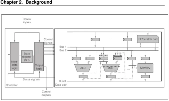
• a controller i.e. the entity which manages the computation, handling the data flow in the data path by setting control signals values, e.g. Functional Units, registers and muxes selectors (see Figure 2.1). Con-troller inputs may come from primary inputs (control inputs) or from data path components (status signals as result of comparisons). It de-termines which operations have to be executed at each control step and the corresponding paths to be activated inside the data-path. Different controller implementations approaches are feasible; however, in HLS the controller is usually designed as a centralized Finite State Machine (FSM). The resulting architectural model, detailed in the following section, is known as FSM with Data-path (FSMD).
2.2
The Finite State Machine with Data-Path ModelThe most common architectural model in high level synthesis is the finite state machine with data-path, as shown in Figure 2.1.
2.2.1 Data-Path
The data-path includes a set of hardware resources, i.e. storage, functional and interconnection units, and defines how those modules are connected each other [171]. All the RTL components can be allocated in different
Chapter 2. Background
Figure 2.1: Typical Architecture composed of a Finite State Machine (FSM) and a Data-path.
quantities and types, and can be customly connected at design time through different interconnection schemes, e.g. mux or bus based. Different archi-tectural solutions could be adopted, allowing optimizations such as:
• multicycling: if each instruction requires exactly one clock cycle, then the clock cycle is lower-bounded by the higher required execution time; to overcome this issue, expensive instructions in terms of de-lay are executed through subsequent clock cycles;
• chaining: it is another solution to the previous problem; instead of reducing the clock cycle, instructions requiring less time are executed subsequentially in the same clock cycle;
• pipelining: instructions are divided in stages, and the clock cycle set to the time required to execute the slower one; if stages are obtained in a way such that there is no concurrency on the resources that execute them, than different stages of different instructions may be executed in the same clock cycle.
Formally, a data path DP can be described as a graph DP (M, T, I), where • M = Mo ∪ Ms ∪ Mi is the set of nodes, corresponding to the DP
modules, i.e. instances of library components, where
– Mois the set of functional units such as adders, ALUs and shifters;
2.2. The Finite State Machine with Data-Path Model
– Ms is the set of storage elements, as registers, register files and
memories;
– Mi is the set of interconnect elements such as tristates, buses and
multiplexers;
• I ⊆ M × M is the set of graph’s edges, i.e. interconnection links. 2.2.2 Finite State Machine
The Finite State Machine (FSM) represent one of the most common mod-els applied in architectural synthesis. Even though they can describe differ-ent kinds of sequdiffer-ential machines, FSMs are typically used for synchronous ones. Synchronous machines are characterized by the presence of an impul-sive signal, i.e. the clock, propagated over the whole circuit, that determines the moment in which the inputs must be evaluated to possibly cause the transition from one state to another of the FSM. Hence, the order in which the inputs are received does not affect the execution, provided they come within the clock cycle. Instead, in the case of asynchronous machines, a global temporization does not exists, and an explicit communication pro-tocol is required to ensure the computation correctness. The asynchronous machines can be classified in two main categories: level machines, in which the system state transitions are caused by changes in the level of the input variables, and impulsive machines, in which the presence or absence of im-pulses causes such transitions.
Formally, a finite state machine is defined as the tuple M = (I, O, S, S0, R),
where
• I represents the input alphabet, • O denotes the output alphabet, • S denotes the set of states, • S0 denotes the initial state,
• R denotes the global relation.
The global relation R is defined as R ⊆ S × I × S × O → {0, 1} such that R(i, u, s, t) = 1 iff given as input i = (i1, i2, ..., in) ∈ I, M goes from
the current state s = s1, s2, ..., sk∈ S to the next state t = t1, t2, ..., tk ∈ S
producing as output o = o1, o2, ..., ok∈ O
The main FSM controller components are:
• a state register (SR), that stores the current state of the FSM model describing the controller’s operation;
Chapter 2. Background
• the next state logic, that computes the next state to be loaded in the SR;
• the output logic, that generates the control signals.
State-Transition Graph
A finite state machine M can be represented by its corresponding state-transition graphG(S, E) where
• nodes s ∈ S are the states of M,
• edges e ∈ E ⊆ S × S denote transitions between states.
State-Transition Relation
Given the global relation R and an input i,the state-transition relation deter-mines the relationship between current state and next state. It is defined as ∆(i, s, t) = ∃oR(i, o, s, t). The state-transition function is usually denoted by δ(i, s, t).
Output Relation
Given the global relation of M, the initial state S0 and an input i, the
output relation gives the output value of M. It is defined as Λ(i, o, s) = ∃tR(i, o, s, t). The output function is usually denoted by λ(i, o, s).
Starting from the above definitions, it is possible to classify the different types of FSMs in three classes:
• Autonomous - The input alphabet is the empty set (e.g. counters). • State based - Also known as Moore’s machines, their output relation
Λ depends only on the current state.
• Transition based - Also known as Mealy’s machines, their output re-lation Λ depends on input values also.
The classical logic implementation of a FSM stores the states in storage ele-ments (registers) while state-transition and output functions are synthesized in combinational logic. Several encodings exist for identifying states in a FSM; the most widespread are logarithmic (binary) and one-hot encodings. In binary encoding, the different states are represented through variables: if the number of states is N , the FSM implementation requires log2(N ) 1-bit
registers However, this encoding requires combinational logic for mapping variables values to states. One hot encoding instead demands more sequen-tial resources, i.e. N 1-bit registers for representing N states. Furthermore,
2.3. Typical High Level Synthesis Flows
one hot implementations are faster than binary implementations, since the latter require decoding logic.
Now the Finite State Machine with Data Path can be defined as the tuple < S, I ∪ B, O ∪ A, ∆, Λ >, where:
• S, ∆, Λ denote the same sets defined for a FSM;
• I ∪B denotes the input language; it is an extension of the set I defined for the FSM, in order to include some of the state variables b ∈ B ⊆ Stat;
• O ∪ A represents the output language, including some assignments a ∈ A ⊆ Asg
FSMDs can be adopted both to describe a design at RT level, or, at higher levels of abstraction, to represent a producer/consumer process where inputs are consumed and outputs are produced. Complex systems could be viewed as processes compositions, where each process is modeled as FS-MDs and communicates with the other ones. Communication is intent to be between control units, between data paths and between control unit and data path. The number of signals and the temporal relations between them during communication define a protocol, e.g. request-acknowledge hand-shakingprotocol [13].
2.3
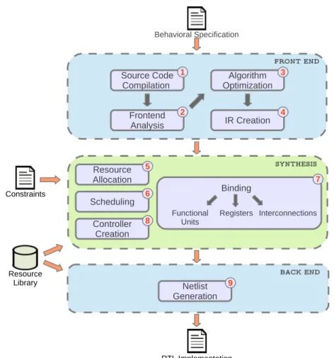
Typical High Level Synthesis FlowsHigh-level synthesis is typically composed of different tasks, summarized in Figure 2.2. There exists many approaches in literature that perform these activities in different orders, using different algorithms. In some cases, several tasks can be combined together or performed iteratively to reach the desired solution. Nevertheless, the HLS flow steps can be grouped in three main macro-tasks:
• Front End:
performs lexical processing, algorithm optimization and control/data-flow analysisin order to build and optimize an Internal Representation (IR) to be used in the subsequent steps. Internal representations de-scribe the specification highlighting specific properties, on which a given task of the synthesis phase will focus on.
• Synthesis:
in this phase the design decisions are taken, to obtain a RTL descrip-tion of the target architecture that satisfies the design constraints. The
Chapter 2. Background
number and type of hardware modules is established and each instruc-tion is scheduled and assigned to one of the available resources that can execute it.
• Back End:
the resulting netlist is generated and reproduced in a hardware descrip-tion language.
Figure 2.2: Typical HLS flow.
Next sections describe each task of the typical HLS-flow. 2.3.1 Front End
An Intermediate Representation (IR) can be described as an interface be-tween a source language and a target language. Such notation should
2.3. Typical High Level Synthesis Flows
scribe source code properties independently with respect to the source/tar-get languages details. Given as input a behavioral specification, the front end translates it in a proper IR, performing lexical processing, algorithm optimization and control/data-flow analysis.
Compilation
The first step in the HLS flow consists in the source code parsing, that trans-lates the high level specification into an IR, as common in conventional high level language compilation, to abstract from language details. The result-ing IR is usually a proper graph representation of the parsed code, and can be optimized or transformed producing several additional representations of the same specification.
Front-end Analysis and Algorithm Optimization
The previous step provides a formal model that exhibits data and control dependencies between the operations. Such dependencies are generally represented in a graph notation, for example in the form of Control Data Flow Graphs. The control/data-flow analysis characterizes some properties of the specification, identifying for example its loop and call structure, or partioning it in Basic Blocks. The analysis step enables further optimiza-tions to better exploit the available parallelism. These optimizaoptimiza-tions are the same ones widely used in optimizing and parallelizing compilers [19], such as dead code elimination and constant propagation, or translation in Static Single Assignment (SSA) form.
Internal Representations Creation
The optimized code is finally reproduced in the form of IR(s) which will be used in the synthesis steps. Common IRs include Control Flow Graphs (CFGs), Data Flow Graphs (DFGs), Control Data Flow Graphs (CDFGs), and Program Dependencies Graphs (PDGs). Flow graphs may represent the input specification at different granularities, for example at the instruction level or at the Basic Block level.
2.3.2 Synthesis
The HLS core consists of different steps strictly connected each other. They can be summarized in:
• Scheduling,
Chapter 2. Background
• Resource Binding.
A desirable feature for HLS is to estimate as soon as possible timing and area overheads, so that later steps could optimize the design. A feasible ap-proach is to start from one of the above mentioned tasks and consequently accomplish the other ones. Then the obtained results could be used to mod-ify the solution of previous steps: in this way the final solution, optimized towards a performance metric, is built incrementally. Another possibility is to fulfill the tasks partially, and complete them as results of other steps are available. For example functional units could be allocated in a first time, and the interconnection allocation could be performed after the binding or scheduling tasks. Allocation, scheduling and binding are all NP-complete problems, thus solving them as a unique task makes the synthesis a too complex process to be applied to real-world specifications. The choice be-tween different ordering possibilities is dictated from the design constraints and tool’s objectives. For example, under resource constraints, allocation could be performed first and scheduling could try to minimize the design la-tency. Instead, in time constrained designs, allocation could be performed during the scheduling; the scheduling process, in this case, could try to minimize the circuit’s area while meeting the timing constraints.
Scheduling
The scheduling task introduces the concept of time: according to the data and control dependencies extracted by the front end all the operations are assigned to specific control steps. Also the concept of parallelism is in-troduced: if dependences and resource availability allow it, more than one instruction can be scheduled in the same clock cycle. A common approach addressing the scheduling problem can be modeled as follows:
• input: DFG of the input specification;
• output: the scheduled DFG, i.e. a graph G(V0, E, C) where:
– v ∈ V0 are the nodes of the (C)DFG, i.e. the operations to be
executed;
– e ∈ E are the edges of the (C)DFG, representing the data flow; – c ∈ C are control steps.
• scheduling procedure: a function θ : V0 → Π(C) assigns to each node
v ∈ V0 a sequence of cycle steps, where Π(C) is the power set of C,
i.e. the set of all the subset of C.
2.3. Typical High Level Synthesis Flows
In the presence of control constructs such as loops, the input specification is usually partitioned in Basic Blocks, which are sequences of code with a single entry point and a single exit point. The scheduling routine then ap-plies to each Basic Block separately. As mentioned before, the scheduling process could be differently constrained, e.g. time or resource constrained. For example, Figure 2.3 proposes the pseudo code of a simple
specifica-avg(a,b,c,d) 1: t1 = a + b 2: t2 = c + d 3: t = t1 + t2 4: avg = t/4
Figure 2.3: Pseudo-code, DFG and scheduled DFG of a program that computes the aver-age of 4 numbers.
tion, togheter with its DFG and a possible scheduled DFG under resource constraints (1 adder and 1 divider available), assuming that each operation needs one control step to be executed.
Resources Allocation
A set of hardware resources is established to adequately implement the de-sign, satisfying the design constraints. Allocation defines the number of instances and the type of different resources from the ones available in the resource library, which describes the relation between the operation types and the modules. Since different hardware resources have different charac-teristics, such as area, delay or power consumption, usually this informa-tions is included in the resource library, to guide both the allocation and the other related tasks. A library Λ(T, L) is characterized by:
• a set T of operation types;
• a set L of of library components (i.e. modules);
The library function λ : T → Π(L), where as usual Π(L) denotes the power set of L, establishes which modules l ∈ L could execute operations of type t ∈ T . On the other hand, the function λ−1 : L → Π(T ) defines the operation type set of l, written λ−1(l), i.e. the subset of operation types
Chapter 2. Background
that a module l ∈ L can execute. Given two operation of type t1, t2 ∈ T , if
t1, t2 ∈ λ−1(l), then they can share module l. Moreover, λ(t1) ∩ λ(t2)
de-scribes the subset of modules that can be shared among operations of type t1 and t2.
Having defined the data-path as a graph DP (Mo∪ Ms∪ Mi, I), thus
allo-cation task must determine the components belonging to each module set Mk. This task defines the allocation functions for each module set.
Functional Units Allocation
The module allocation function µ : V0 → Π(M0) determines which module
performs a given operation. An allocation µ(vi) = mj, vi ∈ V0, mj ∈ M0
is valid iff module mj is an instance of lj ∈ λ(ti), with tioperation type of
vi, i.e. mj can execute vi.
Registers Allocation
Values produced in one clock cycle may be consumed in another one, and in this case such values must be stored in registers or in memory. Liveness analysis can allow different variables sharing a register, revealing if their life intervals overlaps or not, in order to reduce the number of registers, and the design overhead in terms of area. Even in this case, techniques devel-oped in compiler theory are successfully applicable. In particular, after the scheduling, each edge that crosses a cycle step boundary represents a value that must be stored. Thus the scheduled DFG should be transformed to take in account such situation. Given a scheduled DFG G(V0, E, C), the
stor-age value insertionis a transformation G(V0, E, C) → G(V0 ∪ Vs, E0, C)
which adds nodes (storage values) v ∈ Vssuch that each edge e ∈ E which
traverse a cycle step boundary is connected to a storage value. The register allocation functioncould now be defined as ψ : Vs → Π(Ms); it identifies
the storage modules holding a value from the set Vs.
Resources Binding
The allocation task defines the set M of modules that composes the data path. Each module m ∈ M is an instance of a library component l ∈ L. Given a DFG G(V0, E), each operation v ∈ V0 must be bound to a
spe-cific allocated module m. This task takes the name of module or resource binding. A resource binding is defined as a mapping β : V0 → M0 × N;
given an operation v ∈ V0 with type τ (v) ∈ λ−1(t), t ∈ L, β(v) = (t, r)
denotes v will be executed by the component t = µ(v) and r ≤ σ(t), i.e. v is assigned to the r-th instance of resource type t. Module binding must
2.3. Typical High Level Synthesis Flows
ensure that the resource assigned to an operation is available in the cycle step in which the given instruction is scheduled. When the binding is per-formed before scheduling, the scheduling task will take care of schedule operations in order to avoid resource conflicts. Different approaches can be followed to perform the binding; in the simplest case β is a one-to-one mapping, associating each resource to one operation.
Interconnection Binding
The interconnect binding function is defined as ι : E → Π(Mi), and
de-scribes how the allocated resources are connected and which interconnec-tion is assigned for each data transfer. If a resource is shared among differ-ent operations, interconnections include steering logic, whose selectors are managed by the controller. Different solutions could differently affect the design in terms of delay, area occupancy or interconnections complexity.
Controller Synthesis
Once the data-path is built, it is possible to define the activation signals that the controller should generate to activate the data path modules. Controller synthesis can be performed following two main approaches:
• Microprogrammed Controller - each state of the FSM is coded as a microinstruction that specifies the data path activation signals and the next state; if the resulting microprogram is stored in a ROM, the next state can be represented by the ROM address of the next microin-structions (i.e. associated to the next state). If the CFG describing the specification is linear, i.e. there are not conditional nodes, the next state could be computed by a simple counter without indicating it in every microinstructions.
• Hardwired Controller - the controller is synthesized as a combina-tory circuit and registers.
Both the models represent the abstract model of the synchronous FSM. The design complexity increases in the presence of hierarchical structures, or in control dominated specifications. Most HLS flows synthesize hardwired controllers.
Chapter 2. Background
2.3.3 Back-end
During the netlist generation phase, the final architecture design is written out as RTL code, usually described through a Hardware Description Lan-guage such as Verilog or VHDL. To facilitate this task, resource libraries usually include a HDL description of each available module.
2.4
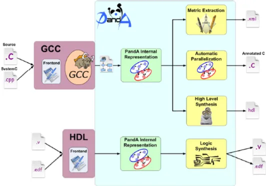
Bambu: A Free Framework for the High-Level Synthesis of Complex ApplicationsAs detailed in next chapter, a multitude of tools implementing the described typical HLS flow are available. Among them we consider as a represen-tative the PandA open-source Framework [10]. PandA covers different
as-Figure 2.4: Panda framework schematic overview.
pects of the hardware/software co-design of embedded systems (Figure2.4), including methodologies to support:
• high-level synthesis of hardware systems;
• parallelism extraction for software and hardware/software partition-ing;
2.4. Bambu: A Free Framework for the High-Level Synthesis of Complex Applications
• the definition of metrics for the analysis and mapping onto multipro-cessor architectures and on dynamic reconfigurability design flow.
The framework offers a complete freely available HLS tool: Bambu [1]. Bambu receives as input a behavioral description of the algorithm, written in C language, and generates the Verilog description of the corresponding RTL implementation as output, along with a test-bench for the simulation and validation of the behavior. This HDL description is then compatible with commercial RTL synthesis tools. From the software design point of view, Bambu is extremely modular, implementing the different tasks of the HLS process, and specific algorithms, in distinct C++ classes. The overall flow acts on different IRs depending on the synthesis stage. The modu-larity of Bambu has allowed a complete integration of the methodologies and techniques described in this thesis, implementing only the algorithms required for the generation of the proposed architectures, while sharing the architecture independent components of the flow, such as the test-bench generation routines. Bambu assists the designer during the HLS of complex applications, aiming at supporting most of the C constructs (e.g., function calls and sharing of the modules, pointer arithmetic and dynamic resolution of memory accesses, accesses to array and structs, parameter passing either by reference or copy).
Chapter 2. Background
2.4.1 Front-end
Bambu has a compiler-based interface interacting with the GNU Compiler Collection (GCC) ver. 4.7 (Figure 2.5) and builds the internal representa-tion in Static Single Assignment form of the initial C code. In particular, the source code is parsed, producing GENERIC trees: GENERIC is a lan-guage independent representation, which interfaces the parser and the code optimizer. The GENERIC code is then translated into the GIMPLE IR, with the purpose of target and language-independent optimizations. GIM-PLE data structures provide enough information to perform a static analysis of the specification, stored in ASCII files. Following the grammar of these files, a parser reconstructs the GIMPLE data structure, thus allowing further analysis and the construction of additional internal representations, such as Control Flow Graphs, Data Flow Graphs and Program Dependence Graphs. The front end analysis process generates a call graph of the whole applica-tion, and the afore mentioned IRs are generated for each call, after GCC optimizations.
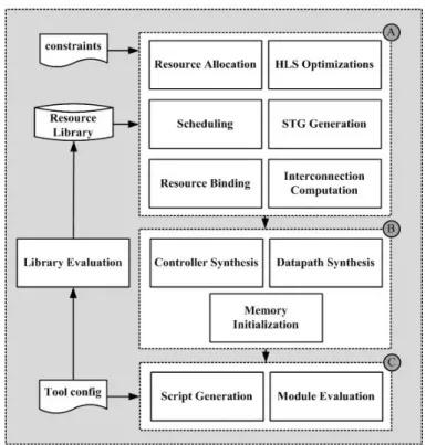
2.4.2 Synthesis
The synthesis process (figure 2.6) acts on each function separately. The resulting architecture is modular, reflecting the structure of the call graph. The generated data-path is a custom mux-based architecture based on the dimension of the data types, aiming at reducing the number of flip-flops and bit-level multiplexers. In its release version, Bambu generates the con-troller as a centralized FSM. For each HLS step, the user can choose among a variety of state of the art algorithms, through configuration files or com-mand line options. The following sections briefly describe some of them, composing the default flow.
Resource Allocation
Resource allocation associates operations in the specification to Functional Units (FUs) in the resource library. During the front-end phase the specifi-cation is inspected, and operations characteristics identified. Such charac-teristics include the kind of operation (e.g. addition, multiplication, ...), and input/output value types (e.g. integer, float, ...). Floating point operations are supported through FloPoCo [61], a generator of arithmetic Floating-Point Cores. The allocation task maps them on the set of available FUs: their characterization includes additional features, such as latency, area, and number of pipeline stages. Usually more operation/FU matchings are
2.4. Bambu: A Free Framework for the High-Level Synthesis of Complex Applications
Figure 2.6: Bambu Synthesis Flow.
feasible: in this case the selection of a proper FU is driven by design con-straints. In addition to FUs, also memory resources are allocated. Local data in fact, may be bound to local memories.
Scheduling
Scheduling of operations is performed through a LIST-based algorithm [148], which is constrained by resource availability. In its basic formula-tion, the LIST algorithm associates to each operation a priority, according to particular metrics. For example, priority may reflect operations mobil-ity with respect to the critical path. Operations belonging to the critical path have zero-mobility: delaying their execution usually results in an in-crease of the overall circuit latency. Critical path and mobilities can be obtained analyzing As Soon As Possible (ASAP) and As Late As Possible (ALAP) schedules. The LIST approach proceeds iteratively associating to each control step, operations to be executed. Ready operations (e.g. whose dependencies have been satisfied in previous iterations of the algorithm) are scheduled in the current control step considering resource availability: if multiple ready operations compete for a resource, than the one having
Chapter 2. Background
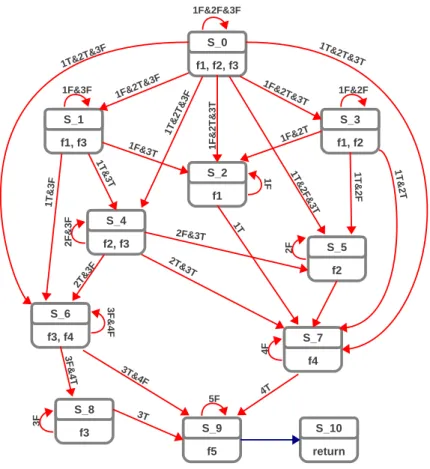
higher priority is scheduled. After the scheduling task it is possible to de-fine a State Transition Graph (STG) accordingly: the STG is adopted for further analysis and to build the final Finite State Machine implementation for the controller.
Module Binding
Operations that execute concurrently, according to the computed sched-ule, are not allowed to share the same FU instance, thus avoiding resource conflicts. In Bambu, binding is performed through a clique covering algo-rithm [178] on a weighted compatibility graph. The compatibility graph is built by analyzing the schedule: operations scheduled on different control steps are compatible. Weights express how much is profitable for two oper-ations to share the same hardware resource. They are computed taking into account area/delay trade-offs as a result of sharing; for example, FUs that demand a large area will be more likely shared. Weights computation also considers the cost of interconnections for introducing steering logic, both in terms of area and frequency. Bambu offers several algorithms also for solving the covering problem on generic compatibility/conflict graphs.
Register Binding
Register binding associates storage values to registers, and requires a pre-liminary analysis step, the Liveness Analysis (LA). LA analyzes the sched-uled program, and identifies the life intervals of each variable, i.e. the se-quence of control steps in which a temporary needs to be stored. Storage values with non overlapping life intervals may share the same register. In default settings, the Bambu flow computes liveness information through a non-iterative SSA liveness analysis algorithm [29]. Register assignment is then reduced to the problem of coloring a conflict graph. Nodes of the graph are storage values, edges represent the conflict relation.
Interconnection Binding
Interconnections are bound according to the previous steps: if a resource is shared, then the algorithm introduces steering logic on its inputs. It also identifies the relation between control signals and different operations: such signals are then set by the controller.
2.5. Conclutions
2.4.3 Back-end
Netlist Generation
During the synthesis process, the final architecture is represented through a hyper-graph, which also highlights the interconnection between modules. The netlist generation step translates such representation in a Verilog de-scription. The process access the resource library, which embeds the Ver-ilog implementation of each allocated module.
Generation of Synthesis and Simulation Scripts
Bambu provides the automatic generation of synthesis and simulation scripts based on XML configuration. Table 2.2 lists the tools already supported.
Table 2.2: External synthesis and simulation tools supported by the Bambu framework. SYNTHESIS TOOLS SIMULATION TOOLS
- Xilinx ISE - Mentor Modelsim - Xilinx VIVADO - Xilinx ISIM
- Altera Quartus - Xilinx XSIM - Lattice Diamond - Icarus Verilog
This feature allows the automatic characterization of the resource li-brary, providing technology-aware details during the High-Level Synthesis.
2.5
ConclutionsThis chapter has introduced High Level Synthesis, describing which are the inputs and outputs of the process, and providing a formal definition of the main phases composing a typical HLS flow. Such flow has been also characterized describing Bambu, showing how the different HLS tasks are addressed in a state-of-the-art framework. The typical architectural model generated through HLS consists of a data-path and a controller: the latter is usually implemented as a Finite State Machine, built according to a stat-ically computed schedule. One of the major contribution of this work, is to provide an alternative model for the controller, which enables the synthe-sis of adaptive accelerators featuring dynamic scheduling. The following chapters will describe the limitations of the FSM design, and will detail how the main tasks composing a HLS flow have been addressed, finally allowing the definition and actual implementation of a complete HLS tool, obtained customizing and extending the Bambu framework.
CHAPTER
3
Related Work
High Level Synthesis has a long history behind: almost four decades of continuous improvements characterize its evolution, turning HLS from a revolutionary idea to a design approach adopted in industry. According to the chronological classification proposed in [125], it is possible to recog-nize three generations in HLS evolution, in addition to a prehistoric period. Each of them has focused on different aspects of HLS, investigating dif-ferent abstraction layers and specification languages, proposing several ar-chitectural alternatives, defining and improving novel synthesis algorithms and techniques. This chapter provides a general overview of the HLS evo-lution, describing the peculiarities which have characterized each genera-tion, and highlighting novelties and limitations of the proposed methodolo-gies. Section 3.1 provides a brief characterization of HLS methodologies, and accordingly, a coarse classification of design alternatives proposed in literature. Sections from 3.2 to 3.5 describe each HLS generation, show-ing how it has evolved year over year. Then, Section 3.6, concludes this chapter, identifying the aspects needing improvements and future research directions, thus highlighting how this work improves the State of the Art.
Chapter 3. Related Work
3.1
HLS Design Methodologies CharacterizationIn order to characterize an HLS design methodology, three main aspects must be considered: the application domain, the adopted specification lan-guage and the final architecture obtained from the synthesis. Applications can be coarsely classified into two categories according to their domain: it is possible to distinguish between data-oriented and control-oriented appli-cations. The first includes those applications performing computation on a massive amount of data, as dataflow intensive specifications and Digi-tal Signal Processing. It is the case, for example, of multimedia applica-tions, since they work on a stream of data. The latter includes applications designed for the control. For example, protocol handlers fall in this cate-gory, since they implement the set of formal rules that must be observed when two or more entities communicate. Applications falling in one rather than the other category have different peculiarities, often making HLS de-sign methodologies developed for one unsuitable for the other. Hence, one of the most relevant challenge in developing an HLS methodology is to make it adequate for both the application domains. Indeed, complex em-bedded system designs often include heterogeneous components. Another variable to define in designing an HLS methodology is the input language adopted to describe the specification. From this point of view it is possible to distinguish between two macro-categories: low abstraction level descrip-tions and high abstraction level descripdescrip-tions. The first category includes languages such as Behavioral Hardware Description Languages (BHDL). There exist several kind of HDLs adopted in HLS, from the primitive ISP and KARL, developed both around 1977, to the more common Verilog and VHDL. Such languages can precisely describe operations and circuit’s or-ganization. For this reason, recent HLS tools consider RTL designs de-scribed through HDLs as the result of the HLS process. The following steps, turning such designs in physical implementations, are delegated to vendor-provided (for FPGA designs) or other logic synthesis tool (such as Synopsis Design Compiler). The category of high abstraction level de-scriptions can be in turn divided into the one of high-level programming languages, such as C, C++ or SystemC, and the one of graphical models, such as extended Finite State Machines (FSMs) or Petri Nets (PNs). The choice of the description language is often tightly related to the application domain. For example, describing a control-oriented application as an ex-tended FSM may result simpler than specifying it by means of an high-level C-like language, often leading to better synthesis results. Finally, the target architecture must be defined. As anticipated in Chapter 2, the architectural
3.2. Early Efforts
model is usually composed by datapath and controller. The most com-mon approaches adopt FSMs for the controller. In addition to centralazied FSMs, which represents the dominant solution, architectural altenatives ex-ist such as hierarchical, dex-istributed and/or parallel FSMs.
Figure 3.1: Main Features Characterizing Design Methodologies in HLS.
Figure 3.1 summarizes the described HLS features. The three identified variables are strictly related each other. A good design methodology should find the right combination between the choice of the specification descrip-tion and the definidescrip-tion of the final architecture, while obtaining good per-formances for both the application domains. In the following sections HLS chronological evolution will be tracked, focusing on the choice made about these three features.
3.2
Early EffortsThe seventies provided the basic ideas on which HLS is based, hence liter-ature refers to this years as prehistoric period. In 1974 M. Barbacci noted that, theoretically, it is possible to “compile”a behavioral description of the specification into hardware, without any information about its structural de-scription, such as synthesizable Verilog, thus setting up the notion of design synthesis from a high-level language specification [84]. His research group at Carnegie Mellon University investigated description languages such as Instruction Set Processor (ISP), Instruction Set Processor Language (ISPL),