1 23
Commons Attribution license which allows
users to read, copy, distribute and make
derivative works, as long as the author of
the original work is cited. You may
self-archive this article on your own website, an
institutional repository or funder’s repository
and make it publicly available immediately.
DOI 10.1007/s10518-014-9701-2
ORIGINAL RESEARCH PAPER
Experimental testing of engineered masonry infill walls
for post-earthquake structural damage control
Marco Preti · Laura Migliorati · Ezio Giuriani
Received: 19 December 2013 / Accepted: 7 November 2014
© The Author(s) 2014. This article is published with open access at Springerlink.com
Abstract The paper presents the results of an experimental campaign on the behaviour of engineered masonry infill walls subjected to both in- and out-of-plane loading. The aim of the research was to develop a design approach for masonry infill walls capable of solving their vulnerability and detrimental interaction with the frame structure when exposed to seismic excitation. Tests on two large-scale specimens and sub-assemblies were performed in order to evaluate the infill deformation capacity, the damage associated with different drift levels, and the mechanical properties of the components. A design solution with sliding joints to reduce the infill-frame interaction and ensure out-of-plane stability, which was proposed in a previous study, was developed and refined with focus on construction details. The aim of sliding joints is to ensure a predetermined mechanism in the infill wall, which is governed by hierarchy of strength and is capable of ensuring ductility and energy dissipation that can be taken into account in the design practice, thanks to the predictability of the response. The two infill wall specimens, one of them including an opening, reached up to 3 % in-plane drift with very little damage and supported an out-of-plane force equivalent to a horizontal acceleration four times the acceleration of gravity. The force-displacement hysteretic curve, sliding at the joints and crack pattern show the efficiency of the construction technique, based on affordable and tradition-like construction processes and materials. The technique, presented here for hollow fired-clay masonry units, can be extended to different masonry infill typologies.
Keywords Damage avoidance · Seismic design · Masonry infilled-frame · Ductility · Full-scale test· Engineered infill wall
M. Preti (
B
)· L. Migliorati · E. GiurianiDepartment of Civil, Environmental, Architectural Engineering and Mathematics (DICATAM), University of Brescia, 43 Via Branze, 25123 Brescia, Italy
1 Introduction
The seismic vulnerability of frame-reinforced concrete (RC) structures due to infill frame interaction has been observed repeatedly (EERI1996,2000;Hermanns et al. 2013) and is well acknowledged in the literature (Paulay and Priestley 1992;Fardis et al. 1999;Dolšek and Fajfar 2008). Typically, infill walls have so far been proportioned and verified as non-structural elements of the building and their role in the non-structural response has often been underestimated or completely neglected in design practice. Several research programs have recently addressed the need for a design of masonry infill walls with appropriate detailing to enhance their seismic behaviour (Calvi and Bolognini 2001;Mohammadi and Akrami 2010;
Preti et al. 2012;Markulak et al. 2013;Facconi et al. 2014). Two different research approaches can be identified, one aiming to strengthen the infill, in order to make it a structural element able to support seismic load, the other to limit the infill frame interaction by reducing the infill strength and stiffness. In both cases the hysteretic energy dissipation offered by the infill is a significant resource in the building’s overall seismic response (Ozkaynak et al. 2013), which can efficiently be taken into account in design only if the infill wall cyclic response is stable and easily predictable. In particular, the predictability of the response is a main issue for engineered infill walls to overcome the vulnerability of infilled frames. Infill walls built according to traditional construction techniques are typically characterized by uncertain and often brittle collapse mechanisms (Mehrabi et al. 1996), which depend on several construction aspects (material and type of masonry units and mortar, geometry, infill-frame contact conditions, etc.), so they are difficult to be accounted for in structural design.
The increasingly important requirement of controlling post-earthquake damage
(DAD-Mander and Cheng 1997;Hak et al. 2012) is an additional stimulus for defining specific construction detailing to obtain ductile infills, capable of absorbing the large deformation imposed by the seismic action without requiring expensive post-earthquake repair. The chal-lenge for a successful design of such engineered infill walls is to meet the above-mentioned requirements with solutions that ensure the thermo-hygrometric performance of the build-ing’s peripheral walls, the affordability of the construction process and its sustainability, according to a life cycle energy analysis approach, which accounts for the entire energy in the manufacture, use and demolition of buildings (Ramesh et al. 2010).
The aim of the research presented here was to develop a design approach for masonry infill walls capable of solving their vulnerability and detrimental interaction with the frame structure when exposed to seismic excitation. The results obtained byPreti et al. (2012) showed the potential of horizontal partition joints (embedded in few masonry mortar beds and acting as sliding joints) to ensure a ductile mechanism for the infill under in-plane loading, preventing the development of the typical diagonal strut mechanism (Paulay and Priestley 1992). This paper presents the new results of that experimental program and also addresses the issue of out-of-plane response for such infill walls with sliding joints, starting with the results collected in previous experience. In this case, the partition joints are made of planks (wooden boards) and their configuration is adapted to the need for out-of-plane capacity control for the two infill layouts, namely with and without an opening. For this kind of masonry infill, the connection to the structural frame is very important. It must ensure support against the out-of-plane action while allowing an adequate degree of freedom for in-plane deformation along the sliding joints. The effectiveness of the sliding joints in limiting in-plane damage to the infill is the key point of this technique since the risk of out-of-plane collapse of the infills may also arise as a consequence of the damage associated with in-plane deformation. As shown in Calvi and Bolognini (2001), in-plane damage can reduce the out-of-plane strength
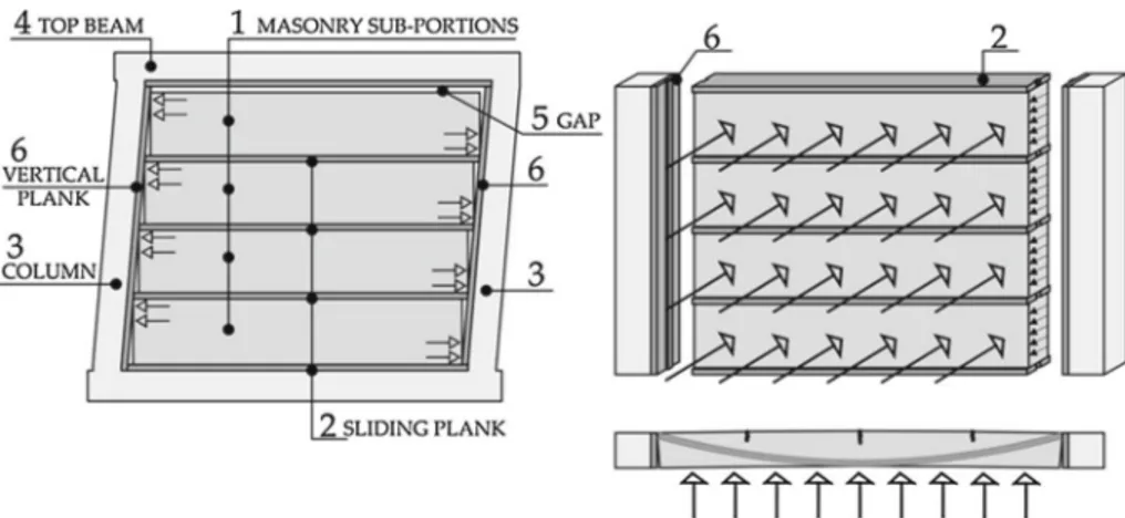
Fig. 1 Masonry sub-portions sliding mechanism and static scheme of the out-of-plane retaining system
of the wall, which under undamaged conditions is often widely in excess of the design action (Morandi et al. 2013;Guidi et al. 2013).
The construction technique, adapted from historical examples (such as himi¸s, colom-bage, Casa Baraccata, Gaiola Pombalina, half-timber, dhajji-dewari, fachwerk) ( Langen-bach 2008;Pompeu Santos 1997;Paikara and Rai 2006;Bettini 2010) is meant to be fast and simple. No expensive materials are involved and no specific manpower skills are required. The effectiveness of the proposed solution for infill masonry walls was tested on large-scale walls that were confined within a single-bay single-story frame subjected to quasi-static in-plane horizontal cyclic loading and out-of-plane push-over load.
2 Construction technique
The construction technique presented here is based on the idea that horizontal joints create preferential lines of weakness along which the deformation of the masonry infill concentrates, in the form of relative sliding between the sub-portions of masonry bounded by joints and columns (Fig.1), protecting masonry from crushing and shear failure. As a result, a ductile response of the infill is obtained, together with reduced stiffness and strength compared to the traditional continuous infill layout, which are pursued in order to reduce infill-frame interaction. A necessary condition for the success of this technique is that the horizontal joints have a sliding resistance lower than the shear strength of the masonry prism and mortar joints, in order to protect them from cracking. In the experimental study proposed, the sliding joints were produced by laying in selected mortar bed joints a plank 50 mm thick and with the same width as the wall (2). In order to reduce friction resistance along the joint and cohesion between the plank and the mortar joint above, a sheet of polyethylene was interposed, simply placed on the upper surface of the table. It is worth noting that sliding along the horizontal joints involves the partial detachment of the masonry sub-portion (1) from the columns of the boundary frame (3), as shown in Fig.1.
This mode of deformation is made possible by the unilateral nature of the in-plane relative constraint between the column and the masonry. In order not to inhibit the sliding mechanism while ensuring the necessary out-of-plane constraint between the infill and the structural frame, it is necessary to create a connection able to prevent the transverse sliding of the wall
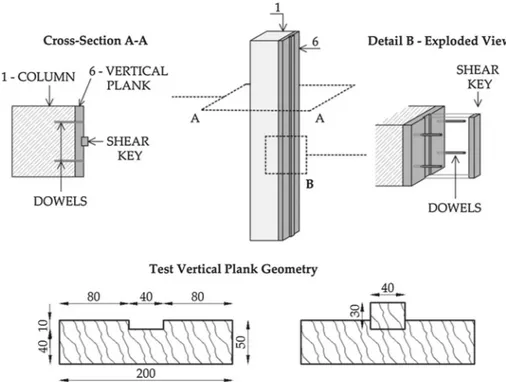
Fig. 2 Schematic of the proposed connection between the infill wall and the columns and description of the
wood components’ constant cross-section as adopted in the test (dimensions in mm)
with respect to the columns, without preventing its detachment in the plane of the masonry. This connection was obtained by interposing an upright, opportunely shaped plank (6, Fig.2) between the wall and the columns (1). The plank was rigidly connected to the frame column with smooth steel dowels, sized to withstand with adequate over-strength the out-of-plane seismic action on the infill wall. Four pairs of dowels per column were used in the test (S275,12 mm diameter) with a 500 mm constant vertical spacing. The surface of the planks towards the masonry was shaped as shown in Fig.2, in order to obtain an in-plane unilateral contact connection plus a shear key working out-of-plane, immersed in the wall peripheral mortar head joint.
The details of the wall-to-column connection are shown in Fig.2. In the experimental test the shear key was obtained with a wooden lath inserted in a vertical groove of the plank (6), proportioned for large shear over-strength. It is worth noting that this connection is meant to remain elastic and rigid under the design out-of-plane seismic excitation on the infill. The spacing, number, length and diameter of the steel dowels for each column and the size of the shear keys should be defined accordingly. A design over-strength parameter equal to 4 was chosen in the test.
Such vertical planks, fixed on the two columns, have the additional purpose of protecting the masonry sub-portions from local crushing arising, due to compatibility, when relative sliding of the infill sub-portions occurs along the horizontal joints. Sliding along the joints would not in fact be possible without the local compressive strains in the contact area between masonry sub-partitions and the columns. As shown in Fig.3, the interposed plank absorbs the required local strains at the masonry sub-portion corners, preventing them from occurring in the masonry, thanks to the ductility of wood and its poor mechanical properties orthogonal to the grain.
(c) (a)
(b)
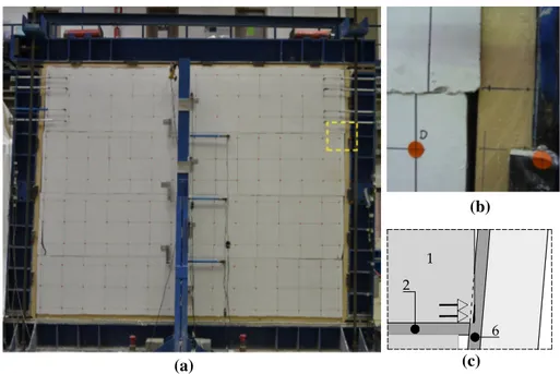
Fig. 3 Picture of wall specimen A at 2.5 % drift (a) and detail of the compressive strain in the contact area
between masonry and plank (b, c) at a sub-portion corner
Fig. 4 Stress–strain curve in the
horizontal directionfor the
masonry prism (perpendicular to the units’ perforation direction) and for the planks in contact with the frame columns (perpendicular to the wood grain)
Figure4shows a comparison of the stiffness and strength of the masonry and plank along the horizontal direction for the wall specimen, obtained from tests on small specimens. The stress–strain (σ–ε) diagram in Fig.4refers to the testing of a masonry prism representative of the masonry wall texture and a 25× 40 × 50 (t × b × h) specimen taken from the plank. It is worth noting the brittleness of the response of masonry subjected to horizontal compression stresses, in this case particularly evident due to the adoption of hollow fired-clay masonry units. As shown in the results, a slightly smaller resistance of the plank compared to the masonry prism (2.2 vs. 2.7 MPa) was enough to protect the masonry from crushing, in agreement with the hierarchy of strength principle.
The experimental results in Preti et al. (2012) showed that the vertical confinement pro-vided by the top beam of the frame (4, Fig.1) results in a progressive increase in friction force along the sliding joints (2) for increasing in-plane deformation imposed on the system. This
(a) (b)
Fig. 5 Components of the experimental masonry infills: full wall (specimen A (a)) and infill with an opening
(specimen B (b)) (mm)
may inhibit the sliding and cause the activation of a strut mechanism. To avoid this risk, it was decided in the experimental tests presented below to detach the infill completely from the top beam with a gap (5), thus nullifying the effect of confinement (7). This choice introduces an out-of-plane vulnerability for the system because it prevents the possibility to activate an arch-resistant mechanism in the vertical direction. To overcome this vulnerability, the wall was organized according to a static scheme that considers the masonry sub-portions stressed out-of-plane to behave like independent beams simply supported by the columns of the frame. Accordingly, the sub-portions were reinforced on both sides with glass-fibre-mesh-reinforced plaster in order to increase the resistance to bending.
3 Experimental programme
The behaviour of the infill walls with sliding joints was studied by conducting two exper-imental tests on full-scale specimens, the first carried out on a full wall (specimen A), the second on an infill with an opening (specimen B) (Fig.5). The walls were subjected to cyclic loading in and out-of-plane. In order to assess the behaviour of the wall with advancing of the damage, the out-of-plan load was applied following the achievement of two significant levels of deformation in the plane, 0.5 and 2.5 % drift, which were arbitrarily taken as design conditions of damage and life-safety limit state, respectively.
3.1 Specimen details
Both specimens, which measured 2,930× 2,460 mm, were made with hollow fired-clay masonry units (200× 250 × 190mm), with a net-to-gross cross-sectional area of 55% in the same plane (Anet/Agross). According to the traditional construction technique, the wall texture
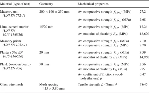
had mortar joints continuous in the horizontal direction and discontinuous in the vertical direction, with an average thickness of 10 mm. A pre-mixed lime-cement mortar was adopted. In both specimens, sliding joints were obtained by laying three 50 mm planks in mor-tar beds at an even distance (Fig.5). As already mentioned, a sheet of polyethylene was placed on the upper face of each plank to minimize the masonry-wood friction coefficient. The experimentally measured mechanical properties of the materials and the coefficients of friction at the sliding joints are shown in Table1.
All the described planks had the same size (50× 220 mm) and material (C14 wood class, EC8, EN2004). The vertical planks were fixed to the columns using 8 smooth steel dowels (S275) with a diameter of 12 mm, infixed into pre-formed calibrated drill holes of equal
Table 1 Mechanical properties of the materials used for the experimental infill wall specimens
Material (type of test) Geometry Mechanical properties Masonry unit
(UNI EN 772-1)
200× 190 × 250 mm Av. compressive strength fc,b//(MPa) 27.2
Av. compressive strength fc,b⊥(MPa) 6.68 Lime-cement mortar
(UNI EN 1015-11/6556)
15/20 mm Av. compressive strength fc,m(MPa) 12.24
Av. modulus of elasticity Em(MPa) 18,620
Masonry prism
(UNI EN 1052-1)
Av. compressive strength fc//(MPa) 7.10
Av. compressive strength fc⊥(MPa) 2.70 Plaster (UNI EN
1015-11/6556)
20 mm Av. compressive strength fc, p(MPa) 9.59
Av. modulus of elasticity Ep(MPa) 14,950
Plank (wooden board)
(UNI EN 408)
50 mm Av. compressive strength fc,w(MPa) 2.56
Av. modulus of elasticity Ew(MPa) 255 Av. coefficient of friction
(wood-polyethylene) µ
0.47 Glass wire mesh Mesh spacing
4.15× 3.80 mm
Tensile strength ft(N/mm)* 38/45
diameter in both the planks and the columns. The shaping of the plank on the face in contact with the masonry was obtained by inserting a rectangular lath (40× 30 mm) in a calibrated groove and nailing it to prevent extraction during testing. As already mentioned, this out-of-plane restraint system was sized with an over-strength coefficient equal to 4, referring to a wall design seismic load of 35 kN, corresponding to an effective horizontal transverse acceleration of 1.6 g (15.7m/s2).
In both specimens a gap of about 30 mm was left between the top of the infill and the intrados of the top beam in order to nullify the effect of the vertical confinement of the beam on the wall infill. The gap was then filled with polyurethane foam to give a uniform surface finish on the wall.
On the full wall (specimen A) masonry sub-portions were reinforced for out-of-plane flexure resistance with 20 mm plaster, reinforced with a fiberglass mesh. The geometrical and mechanical properties are shown in Table1. The continuity of the reinforcing mesh was ensured by overlaying the adjacent mesh sheets by 400 mm. The mesh sheets were also bent into the mortar joints in order to envelop each masonry sub-portion.
For specimen B, a 550× 920 mm opening was created at mid-span. At the sides of the opening two 200× 200 mm wooden posts were hinged at their ends to the top and bottom beams, with a special arrow shapes. The purpose of the posts was to force joint sliding during in-plane deformation where masonry sub-portion continuity is interrupted by the opening. The posts, restrained on the beams, provided the infill with two intermediate supports to give out-of-plane equilibrium to the masonry sub-portions at the opening, by dividing the horizontal span of the infill wall into three lengths. The connection between the masonry and the wooden posts was created with the same solution (shear-key) described for the support between masonry and vertical lateral planks. By virtue of the low bending stress in the sub-portions, specimen B was not strengthened with structural plaster.
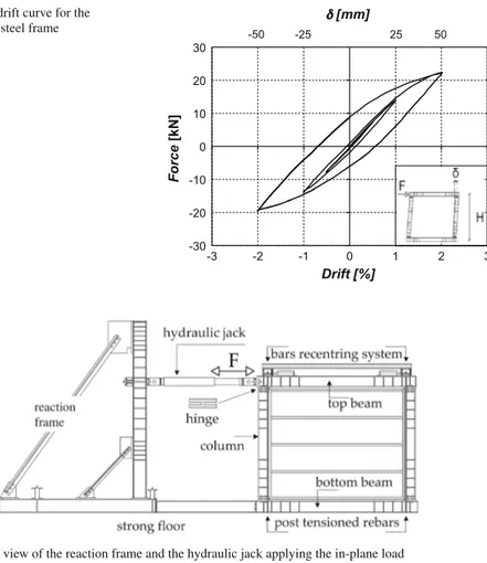
Fig. 6 Force-drift curve for the
bare confining steel frame
-30 -20 -10 0 10 20 30 -3 -2 -1 0 1 2 3 Force [kN] Drift [%] -50 -25 25 50 [mm]
Fig. 7 Lateral view of the reaction frame and the hydraulic jack applying the in-plane load
3.2 Test set-up
The infill wall specimens were built inside a portal frame, equipped with four preformed plastic hinges. The hinges were designed and arranged to reproduce typical structural frame deformation at the ultimate limit state, when the collapse mechanism is fully activated (Preti et al. 2012). For efficiency reasons, the four experimental hinges were placed at the end of the columns. The in-plane system responses, which are described below, include the contribution of the bare frame shown in Fig.6.
Neither the response of the steel frame nor its interaction with the infill was under inves-tigation in this study. The focus here is on the comparison in terms of stiffness, strength, deformation capacity and associated damage, of infill walls made with different construction techniques but having the same boundary and load conditions.
The in-plane horizontal cyclic load was applied by imposing a force at the top beam of the steel frame (Fig.7), the bottom beam being rigidly constrained to the reaction frame. The whole set-up was fixed to the strong floor of the laboratory.
The test portal frame was made of HEB240 profiles for the columns and top beam and a HEB260 profile for the bottom beam (grade S355). The force was applied to the sys-tem with a hydraulic jack acting on the top beam, with the interposition of a cylindrical
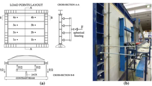
Fig. 8 Elevation, sections (a) and view (b) of the self-balanced system for application of the eight out-of-plane
point load on the infill specimens
joint. Frame deformation was governed by four elasto-plastic hinges obtained by reduc-tion of the resistant cross-secreduc-tion of the steel columns (Preti et al. 2012). The hinges were proportioned to offer the minimum stiffness and resistance against rotation, and provide the necessary shear strength to transfer the load applied by the jack from the beam to the columns.
The in- and out-of-plane balance for the set-up against overturning, was ensured by a total of four external post-tensioned high-strength rebars anchored to the strong floor, located in pairs on the two columns. During the test, for safety reasons, the bars were aligned vertically by re-establishing their undeformed position for each level of imposed deformation, thanks to a system of slides and hydraulic jacks. The bars applied on each column a pre-axial load of 80 kN, proportioned for the only purpose of balancing the whole system against accidental out-of-plane overturning. The re-centring of the bars caused a marginal additional action on the specimens, which increased linearly with the imposed drift, reaching about 5 kN at 2.5 %.
The out-of-plane load on the specimens was applied by imposing a one-way force with loading and unloading cycles of increasing amplitude. The action was applied at 8 points, aligned two by two on the centrelines of each masonry sub-portion (Fig.8).
Since in reality out-of-plane action on the infill occurs approximately as a uniformly distributed load, the experimental load points were placed in pairs on each sub-portion to approximately reproduce the bending moment profile along the sub-portion length (Fig.8a). A hydraulic jack supported by a contrast steel beam applied the load. The ends of the beam were connected to the structural frame in order to obtain a closed and self-balanced system.
The load was transferred from the jack to the eight loading points via a spherical bearing and the two-dimensional distribution frame shown in Fig.8. The point loads were placed at mid-height of each sub-portion, at a distance from each column equal to one quarter of the horizontal sub-portion span. The test was carried out under load control up to triggering of the failure mechanism.
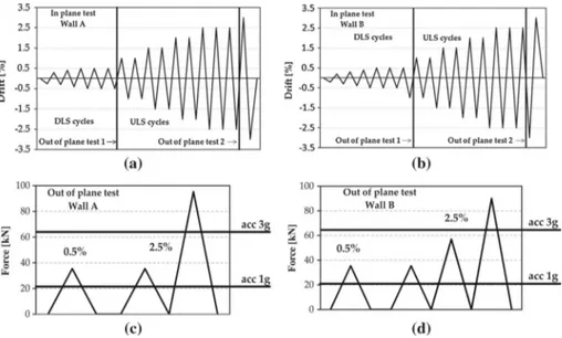
Fig. 9 History of loading applied to the experimental infill walls. In-plane (a) and out-of-plane (c) loading
cycles on the full infill wall (A) and the infill with an opening (B) (b and d)
3.3 Loading protocol and instrumentation
The loading protocol for specimens A and B is shown in Fig.9a and b, respectively. Five in-plane loading cycles of increasing amplitude (up to 0.5 % drift) were applied first, to simulate specimen responses at a damage limit level (NTC(2008), EC8). Ten additional cycles up to 3% drift were applied to assess the performance in terms of capacity and damage. At two intermediate steps (0.5 and 2.5 % in-plane drift), out-of-plane loading was applied on the specimens after re-centring (0 % drift), with the protocol shown in Fig.9c and d. The aim was to assess the specimens’ out-of-plane capacity during the evolution of damage due to in plane loading. The applied load at 0.5 % drift was the design load evaluated for an infill wall inside a five-storey building in the most severe site condition for the Italian context, according to the code “life safety” limit state (NTC(2008), EC8).
The specimen drift, the relative sliding of the masonry sub-portions along the joints and the load applied by the jack were monitored during the in-plane test.
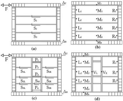
The drift measure was obtained from the ratio of relative displacement of the frame top (!T)and bottom (!B)beams to the specimen clear height. The applied load was measured by a load cell (F) and compared with the jack oil pressure. The series of potentiometric transducers Si(Fig.10) allowed the mapping of joint sliding in the specimens. Figure10c
and d shows the configuration of the gauges during the out-of-plane test for the two specimens, respectively, which were used to measure out-of-plane specimen deformation with respect to the structural frame. On each sub-portion transducers were placed at the point load and at a 50 mm distance from the lateral vertical planks. The opening in specimen B made it necessary to modify the gauge configuration, namely the monitoring of sliding on the two sides of the opening (gauges SL,iand SR,i) and the measuring of the horizontal in-plane
relative displacement of the wooden posts (gauges Pi) during the in-plane test. During the
out-of-plane test, gauges Miwere moved on the side masonry sub-portions and the deformation
Fig. 10 Position of the gauges for measuring infill wall deformations. In-plane displacement and sliding of
the full wall (a) and the infill with an opening (c). Out-of-plane deformation of the full wall (b) and the wall with an opening (d)
4 Test results
4.1 In-plane cyclic response
The results of the in-plane tests carried out on the two specimens are shown in Figs.11,12,
13and14. For specimen A, Fig.11a shows the force-drift diagram, Fig.11b, c the force-joint sliding diagram (Fig.11b, c) and Fig.12the crack pattern. The same are shown for specimen B in Figs.13and14.
4.1.1 Specimen A
Figure11a shows the response of the full infill wall for all the in-plane loading cycles applied. The system was characterized by modest stiffness compared to a traditional infill without joints previously tested under the same experimental conditions (Preti et al. 2012). The sliding mechanism for the masonry sub-portions at the joints was triggered for very small values of drift, < 0.1 %.
The hysteretic curve shows stable behaviour of the wall, with a hardening trend for increas-ing deformation. This trend was probably due to the observed increasincreas-ing compressive strain in the vertical plank in contact with the masonry sub-portion corners (Fig.3), showing the activation of an inclined strut within each sub-portion, driven by the drift of the columns. The plastic component of the local strain on the vertical plank caused a certain pinching in the hysteretic response, which was characterized by a lower and nearly constant resistance for drift levels well below the already achieved peak. Here, the response was governed by
Fig. 11 Force-drift curves for all the in-plane cycles applied on the full wall (a), force-sliding curves in the
3rd cycle at 0.5 % drift (b) and at 2.5% drift (c). Subsequent cycles at the same drift are shown for 2.5% drift only (a), together with the response of a previously tested wall without joints (Preti et al. 2012)
Fig. 12 Full wall: crack pattern after the 3rd in-plane cycle at 2.5 % drift
friction along the sliding joints. Approaching the maximum achieved drift, new activation of the sub-portion strut took place, as evidenced by a recovery of rigidity in the curve.
As shown in Fig.11b and c, sliding along the joints was found to be the predominant mode of deformation of the wall for all cycles of load applied. The measured sliding was uniformly distributed in the three joints and adds up to 80 % of the relative displacement of the top and bottom beam.
(a) (b)
Fig. 13 Qualitative scheme of local deformations (amplified) in the vertical plank (Fig.4) at the masonry sub-portion corners for the full wall (a) and the wall with an opening (b). Linear deformation is assumed along the sub-portion contact lengths based on compatibility, according to an arbitrarily assumed rigid rotation of the columns, and supported by local measurements at the upper sub-portion of the full wall (Fig.12b)
Fig. 14 Force-drift curves for the in-plane cycles applied on the wall with opening (a), force-sliding curves
in the 3rd cycle at 0.5 % drift (b) and at 2.5 % drift (c). Subsequent cycles at the same drift are shown for 2.5 % drift only (a)
It is worth noting that the non-linear strain absorbed by the vertical plank on the columns protected the masonry sub-portion corners from local crushing (Fig.12), which on the con-trary occurred in a previous test without the vertical plank at the column (Preti et al. 2012). Only for large drift of about 2 %, some surface cracking appeared in the masonry corners,
limited to the plaster. The infill specimen reached up to 3 % drift deformation with practically no damage, a very high value compared to traditional masonry infill that typically suffers moderate damage at up to 0.5 % drift and collapse at up to 1.5 % drift (Mehrabi et al.1996;
Preti et al. 2012;Hak et al. 2012;Sigmund and Penava 2014). 4.1.2 Specimen B
Figure14a shows the response of the infill wall with an opening for all the in-plane loading cycles. Like what was observed for wall A, the response of the system was characterized by low initial stiffness and a peak strength for the cycles increasing with the imposed defor-mation. The plot of the cycles applied shows a pinching phenomenon, more pronounced compared to specimen A; local deformation of the planks at the masonry sub-portion corners was observed in this case, too.
As with specimen A, sliding along the joints was found to be the predominant mode of deformation for all the cycles applied, as shown in Fig.14b and c, but it was not uniformly distributed within them. In particular, sliding was maximum in the upper joints and minimum in the lower ones, while it was nearly homogeneous on the two sides of the opening thanks to the two posts framing it. It is worth noting that, despite the presence of the opening, the maximum resistance of this wall was significantly higher than that recorded for the full wall (specimen A). This higher resistance is associated with more significant damage, particularly at the corners of the sub-portions at the window level. The higher resistance of the wall is therefore related to greater exploitation of the masonry sub-portion capacity, probably due to a more complex system of sliding planes resulting from the intersection of the horizontal and vertical wooden elements. Moreover, as shown qualitatively in Fig.13, it seems reasonable that a higher number of masonry sub-portions causes a higher number of sub-portion corners where local large deformation in the wooden plank is required for compatibility, and hence higher internal work associated with the same drift level.
At 0.5 % drift, only cracking at the wood-masonry interfaces was observed. After 1 % drift progressive cracking took place at the masonry sub-portion corners, although it was clearly visible only in the gypsum plaster up to 1.5 % drift. At 1.5 % drift (inter-storey displacement equal to 36 mm) cracks appeared at the lower corners in the masonry units in contact with the bottom beam of the frame, and then propagated into a horizontal crack in the mortar bed travelling throughout the two lateral sub-portions at the base (Fig.15). This particular crack, not observed in specimen A, was probably due to the omission of the plank at the base of the infill creating a bottom sliding plane, so the sub-portions in contact with the bottom beam were well constrained inferiorly and could not develop any sliding, which rather happened on the upper mortar bed, though it was hardly visible.
At 2.5 % drift, failure of the external layer of some hollow clay units at the lower masonry sub-portion occurred. The crack pattern (Fig.15) shows significantly higher damage for specimen B compared to A, but it did not cause any significant change in the specimen response trend (Fig.14). After the out-of-plane test, which is described below, the speci-men was pushed up to 3 % drift, where it showed an asymmetrical response, with a 15 % lower peak resistance, for the negative force applied, compared to previous cycles at 2.5 % drift.
An estimation of the net energy dissipation capacity of the two experimental infill walls was obtained for cycles at 2 % drift. The value was obtained by computing the area enclosed in the hysteretic cycles of the infilled frame, Ahyst, after deduction of the same area for the
Fig. 15 Wall with opening: crack pattern after the 3rd in-plane cycle at 2.5 % drift
Fig. 16 Out-of-plane “total load-deflection” curves for the four masonry sub-portions under out-of-plane
Fig. 17 Full wall: crack pattern
after the out-of-plane test
Fig. 18 Wall with opening—out-of-plane load-deflection curves for the four masonry sub-portions under
out-of-plane load
equivalent viscous damping coefficient, ξhyst, was equal to 15 and 12 % for specimens A and
B, respectively:
ξhyst = 100 ×2π FAhyst
m!m (1)
where Fmand !mare the maximum displacement and net force on the infill in the cycle.
4.2 Out-of-plane response
At the first application of out-of-plane load, after performing in-plane cycles up to 0.5 % drift, the response of both specimens showed a maximum deflection of 3 mm measured at mid-span of the upper sub-portion, about 1/1,000 of the sub-portion horizontal span.
Figures16to18show the results of the out-of-plane test for the second application of loading (after cycles at 2.5 % drift). The total out-of-plane force applied to the specimens is represented on the ordinate of the graphs. The displacement of the control points of Fig.10b and d with respect to the steel frame are represented on the abscissa. For specimen A, Fig.16a shows the deflection of the sub-portion at mid span (control points Ai) and Fig.16b, c the
Ta bl e 2 Synthesis of the experimental results Cycle max drift (%) Peak load (kN) Peak displacement (mm) Secant stif fness at peak (kN/m) To ta l jo in t sl id in g (mm) Strength at zero drift (1st reload) (kN) Progressi ve damage Out of plane strength (kN) Speciment A—full infill w all 0.2 30 4. 86 ,250 4.2 20 Sliding cracks 90 0.5 43 12 .63 ,413 10.0 16 Sliding cracks 1.0 73 23 .03 ,174 19.5 17 Sliding cracks 1.5 97 34 .02 ,853 29.5 17 Sliding cracks 2.0 113 49 .02 ,306 39.0 18 Small plaster detachment 2.5 129 61 .02 ,115 49.0 17 Small plaster detachment 3.0 158 75 .02 ,107 – 29 Small plaster detachment Speciment B —infill w all w ith opening 0.2 44 4. 89 ,167 1.8 16 Sliding cracks 90 0.5 61 12 .64 ,841 7.5 13 Sliding cracks 1.0 102 24 .04 ,250 18.5 18 Sliding cracks 1.5 117 36 .53 ,205 27.5 16 1st shear crack at the base 2.0 133 48 .02 ,771 34.0 14 G ypsum plaster detachment 2.5 148 60 .52 ,446 42.0 14 L ocal crusching at the base 3.0 218 71 .53 ,049 – 25 L ocal crusching at the opening Full infill w all w ith no sliding joints ( Preti et al. 2012 ) 0.08 154 2. 07 7, 000 None Non av ailable 0.2 150 4. 83 1, 250 Horizontal crack at mid-heigth 0.5 188 12 .51 5, 040 Extensi ve cracking + corner crushing 1.0 184 24 .07 ,667 Extensi ve cracking + corner crushing 2.0 154 49 .03 ,143 Diagonal crushing (collapse)
sliding between the sub-partitions and the columns (control points Liand Ri). Figure18gives
the deformation at control points Aifor the wall with the opening (specimen B).
For both specimens the displacement increased from the bottom sub-portion to the top one, probably due to lack of lateral constraint of the frame top beam on the upper sub-portion, which was present between the lower sub-portion and frame bottom beam. The restraint of the bottom beam was partially transferred from the bottom to the upper sub-portions thanks to friction at the horizontal sliding joints, which was proportional to the weight of the above infill portion.
The specimens easily supported the design load (35 kN), even after 2.5 % in-plane cyclic deformation was applied, without evidence of any failure mechanism out-of-plane.
In specimen A, the failure mechanism began at a load of 90 kN, nearly three times higher than the design load and equivalent to an effective transverse acceleration on the infill wall more than four times the acceleration of gravity. The mechanism caused the tensile failure of the glass reinforcing mesh in the plaster at the left vertical crack (Fig.17), which occurred first at the point load of the top masonry sub-portion and then propagated to the lower ones. It is worth noting that the glass mesh failure did not lead to an abrupt collapse. After the mesh failure, the sub-portions actually supported an even higher load with large deformation capacity, probably thanks to the activation of an arch mechanism in the thickness of the masonry allowed by the lateral confinement of the columns. The lateral connection of the masonry sub-portions on the columns was effective, relative displacement remaining below 5 mm at the maximum applied load.
Also in specimen B, which was not strengthened with structural plaster, the collapse mechanism took place at a load of about 90 kN. The mechanism was ductile and characterized by a masonry unit expulsion at the location of the load points in the sub-portion at the window level.
Table 2summarises the experimental performance of the infills in terms of strength, deformation capacity, secant stiffness, total joint sliding and residual strength during load reversals for the first load cycle applied at each drift amplitude. These results are compared with the available performance of the traditional infill wall previously tested (Preti et al. 2012) whose response is shown in Fig.11a. The effectiveness of the sliding joint technique in reducing infill interaction and vulnerability can be observed by comparing the secant stiffness at different drift levels. A dramatic reduction in initial stiffness is observed compared to the traditional infill under the same test conditions. The secant stiffness at large drift levels (e.g. 2.0 %) is similar, but it entails completely different damage conditions.
5 Conclusions
This paper presents the results of an experimental campaign on the behaviour of engineered masonry infill walls subjected to both in- and out-of-plane loading. The aim of the test was to verify the effectiveness of a design approach for masonry infill walls capable of solving their vulnerability and detrimental interaction with the frame structure when exposed to seismic excitation by ensuring large deformation capacity without damage and reduced stiffness compared to traditional solid masonry infills. The infill was designed with horizontal sliding joints that create planes of weakness in the infill texture, where the deformation concentrates. A specific contact connection at the column-infill interface allowed the constraint of the wall out of plane without inhibiting the infill detachment from the column in the plane of the wall. Based on the test results, the technique adopted for the construction of the infill proved to make the infill capable of absorbing 2.5 % in-plane drift with negligible damage, a stable
hysteretic response and no strength degradation. Accordingly, a dramatic reduction in infill vulnerability due to in-plane loading can be obtained, compared to traditional non-engineered masonry infill walls that are typically damaged at up to 0.5 % drift and collapse at up to 1.5 % drift. The infills with sliding joints underwent several load cycles up to 1 % drift with no damage. Some damage occurred in the infill with an opening after 1.5 % drift, but both infills reached up to 3 % drift without collapse.
The insertion of horizontal sliding joints in the masonry infill significantly reduced the stiffness (by 3–10 times) and strength of the infill (about 2 times) for drift levels below 1 % (significant for design). The response of the infill changed from stiff and fragile, governed by the masonry shear mechanisms, to ductile, governed by friction along the sliding joints. Although the complexity of the actual interaction with a real reinforced concrete frame is not described in the test results presented here, such reduction of stiffness can be recognized as strategic in avoiding the detrimental interaction between the frame structure and the non-structural infill wall, which has repeatedly been observed to be one of the main reasons for the collapse of reinforced concrete buildings during earthquakes.
In addition, the hysteretic response of the test specimens showed a non-negligible energy dissipation resource, which was stable and predictable and thus can be reliably accounted for in the structural design of a building. The simplicity and certainty of the mechanism of sliding along the joints is ensured by a design criterion based on hierarchy of strength, which imposes a sliding-joint shear strength lower than masonry sub-portion shear strength. A rough estimate of the energy dissipation capacity for the specimens, obtained by computing the area enclosed in a single hysteretic cycle after subtraction of the frame contribution, gives 12–15 % equivalent hysteretic damping for the two experimental infilled frames at 2 % drift. For the specimen without an opening, virtually no damage occurred in the masonry sub-portions. In particular, at the sub-portion corners, where the rotation of the frame columns caused concentrated compression stresses at the masonry sub-portion opposite corners due to deformation compatibility, the vertical planks acted as cushions in-between columns and masonry, thus preventing the latter from crushing. In fact, at the columns the local duc-tile behaviour of the wooden planks, loaded orthogonal to the grain, absorbed the plastic deformation required, being the wood yielding stress lower than the masonry strength.
The mechanism of deformation of the second infill specimen was not significantly affected by the presence of an opening. In this case two wooden posts on the side of the opening ensured slip activation and reversals at each sliding joint. The comparison of the results for the two infills shows that, despite the opening and in the presence of the two vertical wooden posts, the in-plane strength and stiffness of the infill increased significantly, even if more damage occurred after 1.5 % drift with respect to the infill with no opening and no intermediate vertical posts.
In both infill specimens each sub-portion was designed to resist out-of-plane transferring its tributary load to the columns or the vertical posts thanks to specific shear connections provided at the masonry-column interfaces. Both infills supported an out-of-plane action more than twice the highest predictable seismic action for the Italian context, for which they were designed, according to the codes (NTC (2008), EC8). The failure out of plane was observed to occur with a ductile mechanism, at a load equivalent to a horizontal acceleration 4 times the acceleration of gravity. Such resistance appears not be affected by several cycles applied in plane up to 2.5 % drift and this is consistent with the marginal damage suffered by the infill for in-plane load, even at large deformation.
The study presented here is just part of on-going research (Preti et al. 2014a,b). Several open issues remain to be addressed in future research work on infill walls with sliding joints. The interaction with a real reinforced concrete frame, the different size and shape
of the openings, and the layout of the sliding joints are important issues for applying the technique in design practice. However, the simplicity of the construction details and the use of traditional materials make the construction process fast, affordable and tradition-like, and therefore suitable for a wide range of applications in the construction market. The technique presented here for hollow fired-clay masonry units can be extended to different masonry infill typologies, after satisfaction of the hierarchy of strength requirements.
Acknowledgments The research work was partly funded by Protezione Civile, the Italian agency for
emer-gency response, within the “DPC-ReLuis research project”. The authors are grateful to engineer F. Pasini for his help in carrying out the design and experimental testing of the wall, and to A. Botturi, A. Del Barba and D. Caravaggi, the technicians at the Brescia University’s Materials Testing Laboratory.
Open Access This article is distributed under the terms of the Creative Commons Attribution License which
permits any use, distribution, and reproduction in any medium, provided the original author(s) and the source are credited.
References
Bettini N (2010) Il ritorno della terra cruda per l’edilizia sostenibile: la duttilità dei tamponamenti negli edifici soggetti a sisma. Ph.D Dissertation, University of Brescia, Italy
Calvi GM, Bolognini D (2001) Seismic response of reinforced concrete frames infilled with weakly reinforced masonry panels. J Earthq Eng 5(2):153–185
Dolšek M, Fajfar P (2008) The effect of masonry infills on the seismic response of a four-storey reinforced concrete frame—a deterministic assessment. Eng Struct 30(7):1991–2001
EERI 1994 (1996) Northridge earthquake reconnaissance report. Earthq Spectra 12(S1 and S2) EERI 1999 (2000) Kocaeli, Turkey earthquake reconnaissance report. Earthq Spectra 16(S1)
EN 1998–2001 (2004) Eurocode 8: design of structures for earthquake resistance. European Committee for Standardization, Brussels, Belgium
Facconi L, Conforti A, Minelli F, Plizzari GA (2014) Improving shear strength of unreinforced masonry walls by nano-reinforced fibrous mortar coating. Mater Struct. doi:10.1617/s11527-014-0337-0
Fardis M, Bousias S, Franchioni G, Panagiotakos TB (1999) Seismic response and design of RC structures with plan-eccentric masonry infills. Earthq Eng Struct Dyn 28:173–191
Guidi G, Da Porto F, Dalla Benetta M, Verlato N, Modena C (2013) Comportamento sperimentale nel piano e fuori piano di tamponamenti in muratura armata e rinforzata. In: Proceedings of the XV ANIDIS, L’Ingegneria Sismica in Italia, Padua, Italy, 30 June–4 July, 2013 (in Italian)
Hak S, Morandi P, Magenes G, Sullivan TJ (2012) Damage control for clay masonry infills in the design of RC frame structures. J Earthq Eng 16(suppl 1):1–35
Hermanns L, Fraile A, Alarcon E, Alvarez L (2013) Performance of buildings with masonry infill walls during the 2011 Lorca earthquake. Bull Earthq Eng. doi:10.1007/s10518-013-9499-3
Langenbach R (2008) Learning from the past to protect the future: armature crosswall. Eng Struct 30:2096– 2100
Mander JB, Cheng CT (1997) Seismic resistance of bridges based on damage avoidance design. Technical report NCEER 97–0014
Markulak D, Radic I, Sigmund V (2013) Cyclic testing of single bay steel frames with various types of masonry infill. Eng Struct 51:267–277
Mehrabi AB, Shing B, Shuller MP, Noland JL (1996) Experimental evaluation of masonry-infilled RC frames. J Struct Eng 122:228–237
Mohammadi M, Akrami V (2010) An engineered infilled frame: behaviour and calibration. J Constr Steel Res 66(6):842–849
Morandi P, Hak S, Magenes G (2013) Simplified out-of-plane resistance verification for Slender clay masonry infills in RC frames. In: Proceedings of the XV ANIDIS, L’Ingegneria Sismica in Italia, Padua, Italy, 30 June–4 July 2013
NTC 2008 (2008) Norme tecniche per le costruzioni. D.M. 14 January 2008, Italian Ministry of Public Works, Italy (in Italian)
Ozkaynak H, Yuksel E, Yalcin C, Dindar AA, Buyukozturk O (2013) Masonry infill walls in reinforced concrete frames as a source of structural damping. Earthq Eng Struct Dyn. doi:10.1002/eqe.2380
Paikara S, Rai DC (2006) Confining masonry using pre-cast RC element for enhanced earthquake resistance. In: Proceedings of the 8th U.S. national conference on earthquake engineering, San Francisco, CA, USA Paulay T, Priestley M (1992) Seismic design of reinforced concrete and masonry buildings. Wiley, New York Preti M, Bettini N, Plizzari G (2012) Infill walls with sliding joints to limit infill-frame seismic interaction:
large-scale experimental test. J Earthq Eng 16:125–141. doi:10.1080/13632469.2011.579815
Preti M, Migliorati L, Giuriani E (2014a) Engineered masonry infill walls joints for post earthquake structural damage control. In: Proceedings of the second European conference on earthquake engineering and seismology, Istanbul, Turkey, 25–29 Aug 2014, pp 320–321/372
Preti M, Miglirati L, Stavridis A, Giuriani E (2014b) Performance of ductile infills with sliding joints and design criteria. Technical report n.5-2014, DICATAM, Univerità degli Studi di Brescia, Italy (in Italian) Priestley NMJ (2003) Myths and fallacies in earthquake engineering, revisited. The Mallet Milne lecture,
2003. IUSS Press, Pavia, Italy
Ramesh T, Prakash R, Shukla KK (2010) Life cycle energy analysis of buildings: an overview. Energy Build 42:1592–1600
Santos P (1997) Ensaios de paredes pombalinas. Relazione Tecnica 15/97. NCE, Ministerio do equipamento, do planeamento e do aministraçao do territorio, laboratorio nacional de engenharia civil, Lisboa Sigmund V, Penava D (2014) Influence of openings, with and without confinement, on cyclic response of
infilled RC frames: an experimental study. J Earthq Eng 18(1):113–146. doi:10.1080/13632469.2013. 817362