Sigla di identificazione Distrib. Pago
~ Ricerca Sistema Elettrico NNFISS - LP2 -062 L 1
Titolo
Thermal Hydraulic and Neutronic Core Model for Jules Horowitz Reactor (JHR) Kinetics Analysis
Ente emittente CIRTEN
PAGINA DI GUA
RDIA
Descrittori
Tipologia del documento: Collocazione contrattuale:
Rapporto Tecnico
Accordo di programma ENEA-MSE: tema di ricerca "Nuovo
nucleare da fissione"
Reattori nucleari ad acqua, Reattori nucleari evolutivi,
Analisi di sicurezza
Argomenti trattati:
Sommario
This report, issued in the frame of task LP2-E.2 of the AdP PAR2008-09 assigned to CIRTEN,
outlines the work performed during the period of time spent at the CEA Cadarache Research Centre in the Jules Horowitz Reactor (JHR) project. A thermal hydraulic and neutronic model of JHR core is presented and implemented through a kinetics calculation code (DULCINEE).
Different shutdown procedures are then considered and analyzed in order to verify reactivity
insertions and thermaI hydraulic feedbacks for core power transients.
Note Copia n. In carico a: 2 NOME FIRMA 1 NOME FIRMA
O EMISSIONE
~
%y;a
,
h
NOME G. Grasso«
:
L.
FIRMA
REV. DESCRIZIONE DATA CONVALIDA
P. Meloni
VISTO APPROVAZIONE
di 47
CIRTEN
Consorzio Interuniversitario per la Ricerca TEcnologica Nucleare
Lavoro svolto in esecuzione della linea progettuale LP2 punto E2 AdP MSE‐ENEA “Ricerca di Sistema Elettrico” - PAR2008-09
Progetto 1.3 – “Nuovo Nucleare da Fissione”.
UNIVERSITA’ Di BOLOGNA
Dipartimento di Ingegneria Energetica, Nucleare e del Controllo Ambientale
DIENCA
Thermal Hydraulic and Neutronic Core Model
for Jules Horowitz Reactor (JHR) Kinetics Analysis
Autori
UNIBO : Patrizio Console Camprini Domiziano Mostacci Marco Sumini ENEA: Carlo Artioli CEA: Christian Gonnier
Bernard Pouchin Serge Bourdon CERSE-UNIBO RL 1310/2011 BOLOGNA, SETTEMBRE 2011
2
Contents
1 The Jules Horowitz Reactor Project ... 3
1.1 European Needs for Nuclear Technology ...3
1.2 Research Reactors in Europe...4
1.3 Project Objectives ... 5
At the present time, several partners have already joined the JHR Consortium... 7
1.4 Reactor Layout ...8
1.5 Core Features... 12
1.6 Material and Fuel Tests... 14
1.7 Experimental Devices ... 17
2 Activity Description ... 27
2.1 The DULCINEE Code ... 27
2.2 Neutron Kinetics Model... 34
2.3 Thermal Hydraulic Model... 35
3 Simulations and Results ... 39
3.1 Normal Shutdown Analysis... 39
3.2 Safety Shutdown Analysis ... 42
4 Conclusions and Perspectives... 45
3
1 T
HEJ
ULESH
OROWITZR
EACTORP
ROJECT1.1 European Needs for Nuclear Technology
European demand for electrical power is growing and environmental issues related to greenhouse gas emissions are expected to become more and more relevant in a large number of countries. Then nuclear power is going to be considered as a strategic source in order to meet energy needs, pollution restrictions and fuel dependence.
The development of a sustainable nuclear energy requires several R&D activities on fuel and material behaviour under irradiation with a high level of performances in order to meet the needs and the challenges of the next decades for the benefit of industry, utilities, research and public bodies.
- Considering the number of nuclear power plants all over the Europe, it is worth to highlight how this broad energy network requests a constant improvement of performances and safety features for present but also for future water cooled reactor technologies.
Taking into account the lifetime extension and the progressive launch of Generation III, nuclear power plants which use water as a coolant will be in operation through the entire century. They will require a continuous R&D support following a long-term trend driven by plant life management, safety demonstration, flexibility and economical improvement. Lifespan extension of present Generation II reactors and demonstration of the lifespan of next Generation III reactors are considered major economical stakes: capital appreciation, paying-off production facility, less investment required for energy production.
Experimental irradiations of structure materials are necessary to understand their behaviours and will contribute to operation optimization.
- Fuel technology in present and future nuclear power plants is continuously upgraded to achieve better performances and to optimize the fuel cycle, still keeping the best level of safety. Fuel evolution for Generation II and III is and will stay an important issue requiring developments, qualification tests and safety experiments to ensure economical competitiveness and safety. Experimental tests exploring the full range of fuel behaviour determine fuel stability limits and safety margins, as a major input for the fuel reliability analysis.
- In order to achieve nuclear energy development and sustainability objectives both regarding resources and waste management, the next Generation IV reactors are a very important keystone. That requires innovative materials and fuels which are able to withstand high temperatures and fast neutron flux in different environments. These new technologies are expected to cope with economical and safety performances then challenging technical demonstrations will be needed. Selection, optimization and qualification of innovative materials and fuels face critical issues concerning their in-service behaviour. Utilisation of high performance Material Testing Reactors and other facilities will be necessary to fix these issues.
- In addition, such a research infrastructure will contribute to improve technical skills in the nuclear industry and to train new generations of research scientists, engineers and operators. Indeed, a high performance Material Testing Reactor offers the proper framework to attract younger generations and to cross-fertilize the international skill.
4
International cooperation joined to domestic research infrastructures will constitute a European network for nuclear energy.
1.2 Research Reactors in Europe
European Material Testing Reactors (MTR) have provided technological and research support for 40 years. They give the opportunity to perform relevant experiments in reliable conditions to obtain important nuclear data.
Many countries decided to construct MTRs starting from 1960. For what concerns the French nuclear program, CEA built the SILOE 40 MW MTR in 1963 at the Grenoble research centre. Three years later, at Saclay, OSIRIS was also brought to criticality.
During the last 30 years, CEA operated these two MTRs as strategic facilities to develop a reliable and competitive grid of nuclear power reactors.
At the beginning of 1990, different trend in French demand for nuclear energy obliged industry to reduce its needs. Therefore SILOE reactor was shut down in 1997. Part of the staff was moved to Saclay in order to keep the level of expertise.
OSIRIS reactor is planned to be shut down during this decade. In fact internal safety and performance assessment have shown that even a refurbishment would not allow to secure and to guarantee the availability of the irradiation experimental capacity for the industry and the regulatory body.
Following a broad survey within the European Framework Programs from the European Community, the international community agreed that the need for MTRs in support of nuclear power plant safety and operation will continue in the context of sustainable nuclear energy.
At the same time existing European MTRs dedicated to the industry support are ageing and likely to be shut down due to their obsolescence in order to keep high operational and safety performances. For example, R2 reactor in Sweden has been shut down mid 2005.
Figure 1: MTRs in Europe.
History of research reactors was mainly driven within national policies. The implementation and access to international research infrastructures is becoming a major new trend.
Moreover this perspective is an effective way to manage rationalization and optimization of the research reactors network meeting both requirements of safety, scientific and economic efficiency as well as training and competences management. Like in fundamental physics for decades, the access to up-to-date high performance research reactors should be considered as an opportunity for several countries to get a top level expertise, as an alternative to keep in operation outdated domestic facilities.
5
1.3 Project Objectives
The Jules Horowitz Reactor (JHR) project has been conceived in order to cope with this challenging European scenario. JHR is designed to become a facility able to achieve the needs of the international community through high performance capability.
- JHR experimental flexibility in terms of irradiation devices features is essential to reproduce the operational condition of different power reactor technologies (PWR, BWR, CANDU, HTR, GFR, SFR). In fact it is expected to support present reactors for qualification tests, safety procedures, plant exploitation and lifespan extension, as well as fuel cycle improvement and management.
- High flux capacity that is possible to reach in JHR allows tests to achieve the needs for different nuclear reactor generations such as Gen II, Gen III, Gen IV. High temperature conditions will be available to simulate Gen IV plant challenging environments as well. R&D needs are going to be faced since new fuel development and optimization, cycle and waste management are the main JHR issues in providing data for future nuclear power plants. Structural materials for internals, vessel and cladding are planned to be analysed being strategic for Gen IV safety margins improvements. Sodium-cooled reactors will be simulated as well as VHTR, GFR, SCWR, LFR.
Therefore a thermal flux (<1 eV) in reflector zone will be suitable for fuel LWR studies, on the other hand a fast flux (> 1 MeV) within the core will prove material resistance with high dpa capability (16 dpa/year).
In addition JHR will support new Experimental Reactors and Demonstration Reactors being flexible and future needs oriented.
- In addition JHR test loops are designed to fuel behaviour studies in terms of normal conditions operation, power slope response and limit certification. Moreover it is possible to plan experiments to off-normal and post-failure measurements for particular power variations.
- Particular loops are planned to be devoted to accidental simulation in order to investigate LOCA scenarios for different fuel element and several burn-up conditions. On-line measurements will allow detailed descriptions of fission products during transients. - High capability level is designed to perform more than 10 experiments at the same time in
the core zone and 10 tests in the reflector one. Two power levels are envisaged (100 MW and 70 MW) in order to be able to optimize the partners demand.
- Tests materials and devices will be set in proper laboratories and thanks to examination infrastructure and on-line fission product measurements. Several on-line devices will monitor the tests in order to optimize time and costs.
- Several issues rise also regarding special nuclear material production for civil and medical purposes. JHR is going to provide large amount of radioisotopes for medical utilization (roughly 25% up to 50% of European demand) securing health benefits for population.
The international context in which JHR will be developed is important as well. In fact research and industry frameworks are getting over national policies and domestic tools have no more the required level of economic and technical efficiency.
Meanwhile, countries with nuclear energy need an access to high performance irradiation experimental capabilities to support technical skill and guarantee the competitiveness and safety of nuclear energy.
6
Moreover, many research items related to safety or public policy (e.g. waste management, internal components reliability, vessel performances) require international cooperation to share costs and benefits of resulting public acceptance.
Then JHR will be the starting point of a European network for nuclear research and technical development, scientists and engineers training as well as knowledge and know-how sharing. Therefore this project is driven and funded by the international JHR Consortium gathering vendors, utilities, technical stakeholders and research bodies.
This Consortium was set up in March 2007, construction is going on and JHR is expected to be brought to criticality by 2016.
Figure 2: JHR construction site at the end of 2009.
7
Figure 4: JHR construction site in 2011, reactor building.
Figure 5: JHR construction site in 2011, nuclear auxiliaries building.
At the present time, several partners have already joined the JHR Consortium. - The European Commission and the Joint Research Centre representing Europe - SCK/CEN Mol Research Centre for Belgium
- NRJ/UJV Research Body for Czech Republic - VTT Technical Research Centre of Finland
- AREVA as industrial partner, designer and constructor - CEA which is the reactor owner and manager
- EDF French utility for power generation
- CIEMAT Spanish Research Centre representing domestic safety authority and utilities - VATTENFALL which is Swedish power utility
In addition two associated partners are also involved in the JHR project, namely: - JAEA Japanese Atomic Energy Agency
8
1.4 Reactor Layout
JHR conception and design phase was completed in 2006 and construction site preparation was launched in 2007. At the end of 2008 the excavation procedures were concluded and soil features and mechanical properties were completely coherent with previous evaluations and safety assessments. The concrete pouring started in 2009 and last year anti-seismic bearing pads were accommodated under the reactor building. Level zero floor has been completed this year and construction phase of lateral walls of nuclear island building are ongoing. The JHR building structure is composed by several zones:
- the Reactor Building (RB) and the Nuclear Auxiliaries Building (NAB) forming the nuclear island
- the buildings conceived to host reactor exploitation infrastructure
- the buildings that will host JHR staff and offices, cold assembly workshop and pre-irradiation material storage
Figure 6: Virtual picture of JHR facility.
9
JHR Reactor Building is planned to host the reactor core. Its internal layout points out two
different zones. All the reactor components are settled in the so called “reactor area”.
In the remaining part – namely the “experimental area” – there is room to set up experimental laboratories. In fact here it is possible to perform high quality on-line examinations in order to analyse even very short-lived fission products. Reactor area and experimental area interface was optimised to guarantee operators radiation protection but also high standard acquisition.
Fuel and device underwater transfer are possible through the water channel from reactor core to storage pools in NAB. In the RB the very first part of the channel is the deactivation pool for temporary storage of components just before and after irradiations.
Three cooling loops are then placed in this zone. The primary loop has to assure a proper core cooling both for fuel elements and in-core devices. Regarding the reflector positions, a secondary loop utilizes reactor pool water to cool down all the devices since different needs have to be faced, particularly in the radionuclide producing rigs. Finally a safety third cooling loop is present to assure core decay heat removal until natural convection is set up. Between RB and NAB a particular watertight and airtight separation lock was designed in order to increase the safety standards.
10
JHR Nuclear Auxiliaries Building is composed by laboratories and examination facilities
strictly concerning high irradiation environment. Through water channel, fuel or material samples can be hosted in three storage pools: depleted fuel elements, material test devices and the mechanical components for maintenance and inspections, respectively.
Then two underwater channels allow to reach the hot cells. Here several destructive (DE) and non destructive examinations (NDE) are performed. Two beta-gamma cells are devoted to material samples post-irradiation exams. They are connected to NDE benches and allow also reactor waste management and removal. It is also available a beta-gamma cell for radionuclide transit and dry removal from spent fuel. In addition an alpha-beta-gamma cell is present in order to reach high contamination risks handling.
For what concerns cask management, JHR is designed to be able to allow either “dry mode” loading/unloading procedures or “wet mode” through dedicated hot cells.
NAB also comprises dosimetry and radioprotection laboratories, fission product analysis devices and radio chemistry facilities.
Inter-irradiation controls will be able through proper “cold” workshops, in fact often an on-line check and test parameter correction are necessary to optimize capability, time and costs. Non-nuclear Buildings will host personnel and support staff. Even “cold” workshops for fuel handling before irradiation are set in non-nuclear facility part.
Control rooms are conceived to enhance scientists and operators interface. In fact a pilot control room and an experiment control room are devoted to, respectively, piloting staff and researcher personnel for test monitoring. Operating systems and procedures as well as different experimental configurations have been considered in order to assure the best performances with respect to safety needs, capability and flexibility enhancement.
11
Alpha cell
Spent fuel & radio -isotopes
cell
Multipurpose cell for irradiation devices
NDE posts Front zone of cells
Rear zone of hot cells (cask interface)
JHR hot cells
Multipurpose cell for irradiation devices
& conditioning
Figure 10: Hot cells layout.
In order to comply with the evolution of safety standards and to guarantee long term operations, several feedbacks coming from licensing requests were considered. A new design approach shared several years of experience in PWR reactors with recent EPR conceptions. Particular research reactor features were considered as well.
Consistent 5 levels of defence in depth involved:
- accident and incident preventions through high quality design. All possible scenarios were grouped by event frequency and relative dose calculations were performed as far as safety needs are concerned
- monitoring and detection by means of high standard instrumentation - backup systems for reactor control
- mitigation and management in case of severe accident - off-site procedures for population protection
The safety approach of JHR takes into account a systematic assessment (and the implementation of necessary design modification) of external or internal hazards on the nuclear buildings. Anti-seismic bearing pads were evaluated and qualified to withstand reference earthquakes and to resist during all the plant lifespan.
Building characteristics and JHR confinement are designed to face severe accident conditions. The so-called “Borax accident” (hypothetic beyond design reactivity accident with core melt and explosion) is taken into account in the design of the containment and the water bloc.
Pressure vessel material and design, reflector beryllium qualification and structural ageing effects as well as reactivity optimization and management were taken into account to reach the best performances and meet the regulatory body requests.
In addition, the JHR safety approach will focus on irradiation devices as a potential aggressor of the facility. This problematic involves potentially energetic experiments (PWR loops, safety tests) and/or tests with significant radio isotopic content (eg. Tests on minor actinides).
Moreover, radiation protection issue, fuel and waste treatment and dismantling operations were considered and optimized.
12
1.5 Core Features
JHR core has been conceived in order to achieve high performances since it is going to be the most important research reactor in Europe. Then its core design was aimed at:
- high experimental capability in terms of test positions and cycle management - flexibility and availability for a large number of reactor parameters
- high fast and thermal neutron fluxes in order to simulate broad material and fuel test conditions.
For what concerns flexibility and high capability, several experimental positions are available in different parts of the reactor. Mainly they are divided into in-core positions and in-reflector positions.
In-core experimental positions offer high fast flux since this is an important part of the
JHR core neutron spectrum. Large size locations for relevant dimension devices (85 mm) are designed directly replacing the fuel element. On the other hand, small size locations (32 mm) host the experimental rigs in the fuel element centre. Relevant performances are achievable in both cases: high fast neutron flux (E > 0,9 MeV) up to 5 1014 n/cm2/s are available in small locations, large locations can deliver flux (E > 0,9 MeV) up to 4 1014 n/cm2/s.
In-reflector experimental positions are located within the reflector area, outside the core. It
is possible to enhance capability since device loading and regulation don’t need neither reactor operation nor shut down. Here several moving frameworks allow performance adjustment and flexibility in a number of test positions. In addition fixed in-reflector locations stay within the reflector structure for all the experimental cycle. In-reflector experiments are focused on fuel behaviour tests and in these cases it is possible to reach 500 W/cm linear heat rate in high burnup equivalent fuel samples, moreover even a fast flux of about 8 1013 n/cm2/s is available for PWR pins. Slow ageing processes are also reproduced for vessel and structural materials.
As mentioned, the future experimental programs will be strongly influenced by the market and Consortium members needs. Therefore two different core configurations are foreseen by JHR designers.
The reference core configuration is characterized by a core rack drilled in order to obtain 37 holes. They are planned to host 3 free large in-core experimental positions and 34 fuel elements. Among the latter, 27 control rods and 7 in-core small locations are envisaged. The large core configuration is thought to be the next future JHR evolution. This one will utilize a larger rack with 49 positions among which 43 devoted to fuel elements and 6 to large devices.
It is worth to say that the reference core configuration is able to provide high flux performances whereas the large core one can offer higher experimental capabilities to meet a growing demand for material tests since JHR will be in operation until 2060.
13
Figure 13: JHR core thermal neutron flux. Figure 14: JHR core fast neutron flux.
For what concerns the reference core configuration, many design optimization and feedbacks led to the following ultimate features.
- JHR core is based on a pool tank concept
- the total thermal nominal power is 100 MW, a 70 MW condition is also envisaged mainly for startup procedures until the equilibrium cycle
- primary loop cooling water flows upward through the core, its inlet pressure is 5 to 10 bar, the relative pressure drop is about 6 bar.
- inlet temperature of cooling water is 30°C and temperature rise is about 10°C
- reference fuel is a metallic UMo in aluminum matrix in order not to exceed the 20% enrichment upper limit with respect to non-proliferation issues.
Figure 15: JHR fuel element cross section.
- Since qualification program for UMo is still ongoing, a backup solution fuel consists of U3Si2 in aluminum matrix which will be utilized at least for the startup phase.
- The fuel element is composed by 8 thin cylindrical plates reinforced by a 3 stiffeners structure. The fuel meat thickness is about 0.61 mm and the cladding is 0.38 mm thick. Both fuel an cladding materials don’t reach high temperatures during all the nominal life cycle operations.
- Core neutronic radial reflector is made of beryllium and the axial one is just the primary loop cooling water.
14
Figure 16: Layout of JHR reference core with in-core device positions.
Figure 17: JHR core and reflector device frameworks.
1.6 Material and Fuel Tests
All the JHR Experimental Devices have been conceived starting from identified and expected future experimental needs. The feasibility and the development phases are related to the maturity of the demand and depend on the complexity of the devices to set up. Consequently the instrumentation studies correspond to the current view of the long-term needs, which will be likely expressed during the coming decades. This development is a first initiative towards the set-up of the whole JHR Experimental Devices fleet. It will also depend on the future irradiation market and on the strategy applied by the JHR Consortium members
For what concerns the material tests, different characterizations are expected to be investigated. Material behaviour under irradiation can be studied in connection with different environment conditions such as high temperature, chemical interactions, thermal and
15
mechanical stresses. As mentioned, a large number of nuclear reactor technologies and generations will be properly represented.
Cladding material properties are focused on irradiation growth and strain tests (creep tests)
as well as bowing and swelling effects. Particular devices can host zircaloy samples and set axial strain in order to perform on-line measurements. Cladding resistance to fission gas pressure is simulated through fixed ratios between axial and radial stress in different material cylindrical samples. These ratios can be modified in order to add even the fuel pellet growth phenomena. However particular devices are designed in which biaxial strains are superimposed in order to be able to investigate differential effects.
Figure 18: Device for cladding pressure test. Figure 19: Biaxial strain test device
Concerning the material irradiation growth, experimental rigs will also host specimen with either free or strained parts. Then the same sample will be analyzed taking into account combined effect behaviours.
Figure 20: Device for irradiation growth differential test.
Impact of Zr ageing is also considered since chemical reaction kinetics is strongly influenced by neutron irradiation which induces lattice damages, corrosion and oxidization. Radiolysis due to strong ionizing radiation field – such as in nuclear reactors core – it is important to be simulated and analyzed as well.
Specimen with particular cracks can be irradiated and then analyzed even by means of on-line tests during irradiation cycles, crack resistance tests can be also produced after irradiation and then investigated.
16
Figure 21: Samples for creep behaviour test.
Experiments are also planned to define ionizing environment to study radiation induced diffusion. Several parametric tests are then conceived with respect to mainly temperature and neutron flux spectrum.
Zircaloy properties are proved to be influenced mainly by matrix composition and grain sizes. Secondary precipitate phases control is a key point in determining mechanical properties and corrosion behaviour.
Nuclear reactor technology experience shows that matrix features vary after several irradiation cycles and neutron flux induced phenomena are planned to be investigated among JHR material tests. Microstructure of zircalloys (for instance Zr-4 and M5) in which significant amounts of additive are dispersed, can be irradiated and then analyzed by means of X diffraction or gamma radiography.
The experimental capabilities explained before are interesting for cladding steels but also for
vessel and internal components materials. Swelling due to fast (> 1 MeV) and epithermal
(> 100 keV) neutron spectra are very important as well as toughness variation. Therefore it is planned to design devices in which spectrum parametrical tests will be available and the flux ratio between the two energy groups will be set by the operators.
Irradiation combined with Thermal effects such as creep and ageing are supposed to be
studied for different temperatures and operating conditions.
In addition, hot spots will be simulated in order to understand the effects due to welding within heat affected zones.
Mainly concerning internal components, stress relieving after irradiation periods requests suitable tests for strain components and tightening screws performances.
In addition, bowing material tests are envisaged with respect to requested cladding performances. Several samples are foreseen for different flux irradiation conditions.
Figure 22: Samples for irradiation bowing tests.
Among JHR objectives, nuclear fuel technology research is aimed to develop new materials and to enhance the existing ones.
This research reactor is capable to support all the steps in development process.
Foremost a large amount of small samples are irradiated in order to perform microstructure analysis with respect to specific system parameters (fission rate, temperature, and lattice).
17
Then a first selection is done and just the samples which seem to be able to cope with the targets are considered. General behaviour and macroscopic laws are investigated thanks to different on-line measurements and multi-effect experiments. Long time irradiations are realized in order to reach comprehensive results.
The third step is very close to industrial characterization and the fuel is tested in contexts close to service conditions. Different burnup histories and reactivity variations, as well as different linear heat rate simulations will be available in JHR.
Concerning mechanical and performance tests, several incidental and accidental conditions need to be verified and JHR is capable to guarantee normal and abnormal conditions test channels. LOCA and rod failure experiments are conceived to be realized in dedicated locations as well.
Regarding existing fuel optimization, mainly uranium and plutonium oxides and MOX fuel will be studied even up to high enrichment (> 5%). New microstructure and geometry are under discussion for JHR tests.
Burnable poisons such as gadolinium and erbium are interesting for safety criteria and microstructure features.
Challenging performances are expected from over cladding breach operations and steep power ramps. Burnup improvement is also a key point since sustainability and economical issues about fuel are getting more and more crucial.
It is worth to say that even fission gas release reduction is a major target in fuel performances enhancement. Several fission gas products are planned to be analyzed thanks to on-line laboratories close to reactor pool in RB.
Innovative development of a new generation of materials and fuels, which resist to high temperatures and fast neutron flux in different environments, is necessary for the development of future Gen IV reactors.
There is a need to assess the behaviour under irradiation of a wide range of structural materials such as graphite (VHTR and MSR), austenitic and ferritic steels (VHTR, SFR, GFR, and LFR), Ni based alloys (SCWR), ceramics (GFR). These innovative structural materials are often common to fission and fusion applications. Experimental irradiations have to be carried out in order to study micro structural and dimensional evolution, but also the behaviour under stress. Then new fuels for the different Gen IV systems need also to be characterized or qualified in research reactors.
1.7 Experimental Devices
Several test devices have been designed to comply with future experimental needs. JHR loops will reproduce different thermal hydraulic and chemical conditions to simulate a great amount of nuclear plants. Power and reactivity ramps as well as flexible temperature transients need to be accounted for. Moreover failure and post-failure analysis are allowed thanks to the fission products on-line monitoring. Broad temperature intervals and various coolant procedures are available to test.
The first in-core experimental device is devoted to new cladding material study and qualification. It is called CALIPSO (in-Core Advanced Loop for Irradiation in Potassium SOdium) and to cope with those tasks it has to guarantee:
- minimization of the temperature gradients between samples constituting the experimental batches
18
- possibility to apply a controlled stress to the specimen with relative measurements of resulting strain.
This last feature is a challenging technological issue, and it is driven by both scientific knowledge (creep kinetics quantification) and operational stakes (minimization of budget and time to results by avoiding similar tests in hot cell). Temperature gradient reduction is obtained by means of a liquid metal circulating coolant such as sodium-potassium NaK. On-line measurements and test parameter tuning allow to control the applied stress to the samples. Challenging issues are precise parameter monitoring and adjustment – namely temperature and mechanical strain.
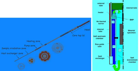
Figure 23: CALIPSO device layout.
Cladding materials like steel, zircaloy (Zr-4), nickel, titanium and aluminium alloys are subjected to high dose rates since it is possible to achieve significant neutron fast fluxes (5 1014 n/cm2/sec). In fact the device is placed in the centre of the fuel element and it can produce displacements up to 15 dpa/year.
The loop shall be autonomous for long-term irradiations and shall embark in a small volume all the components needed to ensure forced convection in the test section. Electromagnetic pumps are able to offer a proper cooling mass rate and an adjustable length heat exchanger can allow NaK temperature control. It removes gamma heating and permits sample temperature to vary from 250°C to 400°C to simulate LWR conditions, 600°C level will reproduce future Gen IV reactors.
The sample–holder designed for CALIPSO loop is based on a concept used in the OSIRIS MTR. Designed firstly for LWR needs, it embarks 3 experimentation bases holding 3 pre-pressurized tubular samples placed at 120° on each
The design phase of the CALIPSO loop is now completed and some critical components (such as the electromagnetic pump or the embarked heat exchanger) have been studied more in details and the manufacturing of prototypes has been launched.
A simpler design of the CALIPSO loop is also under development, it is operated with natural convection and it is called MICA (Material Irradiation CApsule). It will be able to hold a more sophisticated sample-holder containing about 10 tubular specimen placed vertically in the centre of the device. In the same way it will be possible to apply a controlled biaxial stress on tubular samples (axial and circumferential) and to perform on-line measures about the resulting strain. Creep behaviour, deformation and swelling are measured through on-line instrumentation. Stagnant Nak temperature is tuned by 6 different electrical heaters.
19
MICA will be utilized for irradiation growth tests, stress controlled creep experiments and dynamical tensile measures. It is possible to get axial and bi-axial stresses in order to provide on-line qualifications.
A first step towards this design is a sample holder able to apply a controlled uniaxial stress on specimen made of SiC fibres. Its operation in an Osiris device has been completed.
Figure 24: Layout of MICA device loop.
In addition to experimental devices, innovative sample carriers are under definition phase for the future JHR experiments. Composite SiC/SiC materials are considered for structure in GFR. These are studied in CEDRIC sample carrier (Creep Experimental Device for Research on Innovative Ceramics).
Within this it is possible to investigate creep behaviour in high temperature and fast neutron flux conditions. On-line measurements and control are applied to two different samples. The first is just irradiated and a pre-defined strain is applied to the second. In-core position in the middle of the fuel elements are utilized to reach the proper fast flux.
A broad temperature range is achievable from 600°C to 1000°C in helium atmosphere. The define phase started in 2007 and a prototype was realized at the beginning of 2008. Then it was irradiated in OSIRIS reactor. An enhanced version is planned for JHR.
20
A different sample carrier is devoted LWR needs. In fact during normal or incidental operations, fission gas release and pellet-cladding interactions generate complex multiaxial stresses to cladding material. The MELODIE (MEchanical LOading Device for Irradiation Experiments) has been designed to provide high quality data in order to enhance PWR cladding material resistance and fuel burnup. A joint effort between CEA and VTT (Finland) developed this carrier which has been tested in OSIRIS reactor and which is expected to be improved for the JHR.
Fuel irradiation performances for what concerns LWR are realized within a number of experimental devices. First and foremost MADISON device (Multi-rod Adaptable Device for Irradiations of experimental fuel Samples Operating in Normal conditions) has been optimized in order to host 4 PWR (including VVER) or BWR rods at a time complying with industrial needs.
This in-reflector device is conceived to investigate fuel behaviour during normal operation conditions with no cladding failure. A moving framework will allow different flux levels and operational flexibility. MADISON loop can set up proper thermal hydraulic and chemical environment related to different reactor technologies (PWR or BWR).
The aim of MADISON tests is of studying mainly microstructure and fission gas release in connection with burnup or linear heat rate generation (LHRG) for up to 400 W/cm linear power in high burnup representative fuel. Slow power variations will reproduce transient operational scenarios. Moreover cladding corrosion will be produced even during long irradiation cycles (up to 3 years).
Figure 26: Layout of MADISON device loop.
Challenging experimental features arise from the need for a very homogeneous and flat radial neutron flux profile by means also of shielding components. High performance measurements are required. In addition, different chemical environments are available according to reactor type being simulated (PWR or BWR).
The feasibility study of this loop is on-going in collaboration with the Institute for Energy Technology (IFE), operator of the Halden research reactor (HBWR, Norway).
Test device head
Heat exchanger
Tight connectors
Fuel rod
LVDT
Downcomer tubes Test device head
Heat exchanger
Tight connectors
Fuel rod
LVDT
21
Figure 27: Moving structure for reflector devices Figure 28: MADISON device cross section.
For what concerns fuel tests beyond operational limits, the ADELINE device was designed. Its aim is to investigate extreme fuel conditions and to simulate failed fuel elements in normal operations.
It can also reproduce incidental events for either PWR or BWR rods.
Hosting one fuel sample, several power ramps (up to 660 W/cm/min) are available since linear heat generation rates of about 620 W/cm and 390 W/cm are allowed for burnup of about 40 GWd/t or 90 GWd/t, respectively.
Several power transient performances are allowed since ADELINE loop is placed within the reflector and a proper thermal flux is available, moreover a moving structure will optimize irradiation time and levels.
Figure 29: ADELINE device loop Figure 30: ADELINE device cross section.
High quality LHGR measurements by means of thermal balance, neutron detection and post-test gamma scanning can offer optimized performances. Since failure post-tests are envisaged, the
22
loop is equipped with chemical analysis and filtration instruments in order to cope with contaminated effluents. Connections with fission products laboratory will provide on-line evaluation of release gases, a particular sweeping gas circuit is also present.
Rod internal over-pressurization and gas releasing with respect to LHGR as well as fuel melting will be also target tests for ADELINE device.
Turning to safety needs for accident simulations, LORELEI (Light water One Rod Equipment for LOCA Experimental Investigations) is a JHR experimental device properly planned to deal with LOCA scenarios. The feasibility study of a dedicated capsule has been started since the end of 2007.
The target is to be able to reproduce the typical temperature time history and the quenching phase of a LOCA sequence on a single instrumented fuel rod, based on a single-effect approach.
The current LORELEI considers a in-reflector device placed on moving components capable to properly set the neutron thermal flux – namely fission power. In addition, the location can enhance flexibility safety features since it is outside reactor vessel.
Figure 31: LORELEI device loop Figure 32: LORELEI loop layout.
Moreover it will study thermal, mechanical and radiological aspects in severe LOCA accidents. In particular, it is expected to adapt it for tests on a small bundle, in order to point out some fuel bundle effects. In fact it is necessary to know more about clad ballooning and burst phenomena, high temperature corrosions and post quench behaviour of fuel rods. For these tests, the non-destructive examination benches will be a crucial support to gain quickly a first detailed status of the tested sample.
The first part in LORELEI test program regards sample irradiation in order to create a representative fission product inventory for radiological and microstructure purposes. Then a dry-out phase is simulated by means of gas injection for liquid evacuation. Just in the bottom part liquid water is planned to remain to create steam atmosphere through electrical heaters. Heat-up phase induce the temperature to rise through on-line controlled ramps and last quenching part are achieved injecting water and performing all tests measurements for mechanical interaction and radiological contamination through gas and liquid sampling lines. Another experimental performance in connection with Gen IV technology is under design concerning minor actinides transmutation issues. During this process a larger amount of helium is produced when fission occurs with respect to conventional fissile material burning. Then cladding is designed to withstand higher pressure values and influenced by fission gas
23
fuel retention. In addition swelling material phenomenon becomes more relevant in terms of cladding operational lifespan.
Figure 33: Device for transmutation studies.
A transmutation device is then set up in order to burn minor actinides using a thermal neutron flux but utilizing a representative fuel with uranium and minor actinides dispersed in matrix in order to reach the same fission gas production level.
Moreover it will be needed a fast spectrum test to be able to reduce uncertainties on fuel behaviour, get more data about fuel and cladding material interactions and investigate cladding failure conditions.
24
JHR equipments for post-test analysis are composed by several Non Destructive
Examination benches (NDE) in order to increase the experiment quality on full devices or
sample holders.
Underwater NDE instruments are located in reactor pool (RB) and in storage pools
(NAB).These are dedicated to initial checks of the experimental load state just before the beginning of irradiation (after transportation or insertion in the device). Adjustment of the experimental protocol will be also possible after a first irradiation run.
Since they are very close to reactor core, short delays are achievable between device extraction and sample measure. In the same way they will be used also for final test measurements. It is possible to perform neutron scanning examination thanks to particle flux at mid-core level. In addition gamma and X ray scanning systems are placed in reactor and storage pools. Those instruments utilize, respectively, gamma self-emitted rays from fuel elements and activated components or X rays produced by means of a LINAC linear accelerator.
The design phase of two underwater photonic imaging systems has just started end of 2007 in collaboration with VTT (Finland).
Moreover several analysis will be possible such as: Photon Emission Spectrometry (PES), Photon Emission Computerized Tomography (PECT), X-ray Transmission Radiography (XTR), X-ray Transmission Computerized Tomography (XTCT). Such techniques proved data concerning material densities (transmission) and fission products location (emission).
25
Figure 36: Plot of the x-ray scanning system.
Hot cells NDE instruments were also conceived and they will be utilized for sample
inspections in hot cells.
They will allow visual checks and sizing inspections. Corrosion and material thickness will be performed as well as crack measurements after particular irradiations. Mainly useful for irradiated fuel, a large number of measures are available even in strongly ionizing environments.
Figure 37:Layout of NDE devices in hot cells.
Besides the bilateral collaborations set-up for the development of some equipment already mentioned, the JHR facility design and operation is largely open to international collaboration. A first step was the signature in March 2007 of a Consortium Agreement for the reactor construction and operation. As an important subsequent step, a new European Commission Framework Program (MTR+I3, “MTR plus” integrated infrastructure initiative) has been launched for 3 years from October 2006. This programme reinforces a major evolution toward the following key objectives:
- Building up the European MTR Community, including new facilities as well as existing ones (high performance MTRs as well as flexible small power facilities). Special attention is paid on complementarities between MTRs: operators training with staff
26
exchanges, manufacturing practices, measurement best practices, opening accesses for testing experimental devices innovations.
- Establishment of the JHR as a new European MTR, because cross fertilization with existing European material testing reactors is important to take advantage of the available experience and of the impetus provided by the JHR project.
- Support state of the art design, fabrication and test of innovative irradiation devices or components with associated instrumentation. This addresses a comprehensive set of topics strategic for both present and future power reactors.
27
2 A
CTIVITYD
ESCRIPTION2.1 The DULCINEE Code
Power transient evaluations have been performed through the DULCINEE kinetics code. It has been developed by CEA and IRSN (Institut de Radioprotection et de Sûreté Nucléaire) and it was mainly used and validated during safety tests at CABRI reactor in Cadarache. It was conceived to analyse normal and accidental reactivity insertions, fast power evolutions, loss of flow conditions and rises in coolant inlet temperature.
A point wise kinetics approximation model is utilized and it takes into account six neutron precursor groups. External reactivity and thermal feedbacks are accounted for and the reactivity term in neutron kinetics equation is updated. A Runge-Kutta fourth order method is then implemented to solve power evolution supposed to be proportional to the neutron population of the system. Then gamma heating is evaluated by inserting relative power ratio. The coolant temperature field is then computed through mass, linear momentum and energy conservation whereas solid temperature distribution is obtained through the solution of two-dimensional Fourier’s equation. The code enables double-phase modelling which is not considered hereafter since JHR flow is always single phase due to its thermal hydraulic conditions.
The shape of the fuel element can be either cylindrical or described by plate geometry. The code considers neutronic parameters with respect to two geometrical regions of the core. These are defined through fuel cell number, volume, average flux and relative profile in order to distinguish the hot channel from the rest of the core.
Moreover mass rate is imposed as well as inlet pressure and enthalpy of the coolant. Thermal properties of materials are then considered and tabulated by the user since they are functions of temperature. Fluid properties are computed for pressure below 105 Pa and tabulated for pressure above 105 Pa.
Regarding thermal hydraulic evaluations the velocity field is supposed to be mono-dimensional and the fluid homogeneous. As mentioned before, conservation equations are solved in every node of the domain for, respectively, mass, linear momentum and energy.
!" !t + !
( )
"v !z = 0 !( )
"v !t + !( )
"v2 !z = #"gcos$ # !p !z # F !( )
"h !t + !( )
"hv !z = GHere the velocity term is oriented in z-direction, F is the friction force and G accounts for the heat generation term per unit volume in the coolant. According to heating phenomena in nuclear reactors, the most important contribution is due to fissions and then to heat flux through the wall. A balance relative to this flux ! at the external perimeter gives the Q term respect to a coolant flow cross section: S Q=!p
28
Finite differences method puts the previous system into the form showed hereafter. Indexes P and m define, respectively, the time evaluation and the node location for every calculation step. Node distances are set by the user and time step is computed starting from the latter and the average velocity in the channel. The term G points out the meaning of the gamma ratio coefficient CGAM: G=Q
(
1+CGAM)
Void fraction ! is used to find density at every node through the ones of liquid and vapour .
!mP"! m P"1 #Tcanal + qmP " qmP"1 #z = 0 qmP " qmP"1 #Tcanal + 2 s q
( )
m P q m P " q m"1 P #z + q 2( )
m P s m P " s m"1 P #z + PmP" PmP"1 #z = F hmP " hmP"1 #Tcanal + q ! $ %& ' ()m"1 P"1 hmP"1" hmP"1"1 #z = G !m"1 P"1 !mP =! l hm P( )
( )
1"* m P +!v( )
PmP * m PWhere P means the total pressure which considers the static one and the gravity force, q is the mass rate per unit surface and s is the average specific volume defined with the following
expression that holds for relatively low pressures: s=
(
1! Xr)
2 "l
(
1!#)
+ Xr 2 "v# while X is the rsteam quality of the coolant.
Boundary and initial conditions solve a stationary problem. Initial density is computed for a single phase fluid since liquid features are set by the user.
q0 P = q 0 h0 P = h 0 P0P = P 0 qm 1 = q 0 Pm 1 ! P m!1 1 "z ! q2 #2 $ %& ' ()m 1 #m 1 !# m!1 1 "z = F hm 1 ! h m!1 1 "z = G q0
Static solution scheme starts from the first node in which enthalpy is known and goes on in this way: hmP = 1! q " # $% & '(m!1 P!1 )Tcanal )z # $ % % & ' ( (hm P!1+ q " # $% & '(m!1 P!1 )Tcanal )z hm!1 P!1+)TcanalG "m!1 P!1
Then it is possible to obtain density for liquid phase since it is a function of the enthalpy and quantities related to the previous node.
29 !m P
( )
liq =!l hm P( )
( )
1"# m"1 P +!v Pm"1 P( )
#m"1 PNow a guess density value can be used in mass and momentum conservation equation in order to reach the convergence.
From mass equation it is possible to know the mass rate qmP
( )
!mP ( )i 1"
and, in the same way,
the momentum equation gives total pressure PmP
( )
!mP ( )i"1 . Both are depending upon guess hypothesis and this trick can be repeated until the chosen convergence is reached.!m P
( )
( )i " !m P( )
( )i"1 <#Proper convergence values can be fixed by the user both for density and for pressure iterations. At this point the internal loop is completed. For every node distribution the external time loop is solved as well.
For what concerns the temperature field in the solid parts of the domain, the code solves the Fourier’s equation neglecting axial conduction and taking advantages from angular symmetry. In fact it yields
! cT
( )
!t = 1 r ! !r " r !T !r # $% &'(+ Pfissfor cylindrical geometry and
! cT
( )
!t = ! !r " !T !r # $% &'(+ Pfissfor the plate fuel elements. In both cases c is the heat capacity and ! is the thermal conductivity of the material.
Initial conditions can be computed as stationary case or inserted by the user. Anyway it is possible to state that T
( ) ( )
r,0 =T0 r . Boundary conditions accounts for heat exchange between external surface of the cladding and coolant bulk temperature.!"T
"r = hc
(
TW # !T)
The heat convection coefficient is computed through Margoulis number and proper correlations. It is also allowed to describe different materials and their thermal resistance in terms of contact between solids. Then it is allowed to impose a thermal conductivity since the heat flux is related to temperature difference in this way.
! Rth = T2" T1
If a mechanical play has to be taken into account, models are available to update geometrical dimensions with respect to temperature and then to express the related thermal resistance.
30
Moreover finite volumes method is used with respect to either cylindrical or linear shells. For every node a shell volume !V placed on it is considered, it is split in two portions and an energy balance is carried on through Fourier’s equation. There is then a right (plus) part and a left (minus) part.
1 r! " "r # r ! "T "r $ %& '() r! dV+ f r*V
+
! dV *V+
= " "t( )
c T r ! dV *V+
Which gives the expression given below for a specific node i at a distance ri from the centre
either of the plate or the pin, the interval amplitude is set by the user through hi parameter
which means the half distance between two nodes. These hold for both cylindrical ! =1and plate geometry ! =0. ! r"#T #r $ %& ' ()ri*hi*1 ri+hi + f ri*hi*1 ri+hi
+
r"dr= # #t( )
cT ri*hi*1 ri+hi+
r"drIt is worth to say that for this type of equation in mono-dimensional domain the final expression of the system is like the following:
VM ! UM
(
)
Tit!1+ 3VM + 3VP + UM + UP(
)
Ti t + VP ! UP(
)
Tit+1= = VM + UM(
)
Ti!1 t! "t + 3VM + 3VP ! UM ! UP(
)
Ti t! "t + VP + UP(
)
Ti+1 t! "t + + f ri+ 1 2hi ri+ hi(
)
# +1 ! rii # +1 # + 1 $ % & & ' ( ) )+ fri! 1 2hi!1 ri# +1! r(
i ! hi!1)
# +1 # + 1 $ % & & ' ( ) )in which the right hand side might be thought as a source term depending only on previous time step data.
Where VP= c ri+1 2hi ri+ hi
(
)
! +1" r i ! +1 ! + 1 # $ % % & ' ( ( 1 4)Tconduction VM = c ri" 1 2hi"1 ri! +1" r(
i" hi"1)
! +1 ! + 1 # $ % % & ' ( ( 1 4)Tconductionare terms which take into account the time-dependent amount of thermal energy in volumes placed in right (VP) and left (VM) position with respect to the considered node. Obviously the very first VM and the last VP are always equal to zero.
Conversely UP= !ri+hi
(
ri + hi)
" 4hi UM = !ri#hi#1(
ri+ hi#1)
" 4hi#131
account for thermal conduction terms. They are in the same way referred to the left and the right side of the volume.
This form of the equation is easy to consider different media and interfaces. In fact it is possible for the user to set particular values of these coefficients if a material interface is present. In the case of plate fuel elements the highest possible thermal conductivity is inserted in order to account for the perfect contact between cladding and fuel meat.
Power generation term is computed starting from axial and radial profiles, respectively g(z) and h(r). Volumes V and average neutron flux r ! are inserted for every region, as well as r
height H , number of fuel elements r NB and pellet surface r S . Then it is possible to r
compute the proper generation term as showed through a general integral below. Needless to say the generation term is just the function to be integrated by means of the profiles which are properly normalized by the code, weighting function is also the ratio between the power of different regions to the total one.
Ptot = Ptotg(z)h(r) !rVr !rVr r
"
V##
Hdz dS rNBrSrFinally it is easy to recognise that the equation form for temperature T at a given time step is the following:
aiTi!1+ biTi+ ciTi+1= Si
T1 = 0
TN+2 = !T i" 2, N + 1
[
]
Here N is the total amount of nodes in the fuel and in the cladding volumes. The first temperature is obviously equal to zero in order to obtain a general method for every point and the last one is exactly the coolant bulk temperature, in fact through setting the thermal conductivity value to adjust it for convection process it is possible to use that one as a boundary condition.
The matrix associated to this system is tri-diagonal and then a simplified Gauss method is useful to solve it.
Ti =!iTi+1+"i
TN+1 ="N+1
i# 2, N
[ ]
with the following variables:
[ ]
1 1 2, i i i i i i i i i i c b a c b a i N ! ! " " # # # = + # = + $ 2 2 2 2 2 2 c b S b ! " # = =32
Kinetics calculations are mainly oriented to power evolutions and then it is important to explain how the code numerically evaluates that.
DULCINEE was developed for safety studies in experimental reactors and then very short power changes were planned to be analysed. In addiction small experimental reactors allow point wise modelling since neutronic parameters are coherent with these assumptions.
In fact the whole neutron population number n(t) is supposed to behave like a point and only integral evaluations are performed neglecting space dependence. Six neutron precursor groups are taken into account through their ci concentrations.
dn(t) dt = !(t)"# $ n(t)+ %ici i=1 6
&
dci(t) dt = #i $ n(t)"%ici(t)Supposing the neutron population proportional to the total thermal power it is possible to write: dP(t) dt = !(t)"#eff $ P(t)+ %iCi i=1 6
&
dCi(t) dt = #i $ P(t)"%iCi(t)Neutronic parameters of the system yield ! , the different eff ! values and the prompt i
neutron lifetime !. Reactivity ! is a function of time and it accounts for all the different (t) feedbacks taking place during the simulation.
Mainly it is possible to distinguish three contributions to total reactivity:
!(t) = !0+!ext(t)+!fb(t)
The first term is associated to an initial reactivity if the reactor is not critical at the beginning of the simulation. The external reactivity is then considered in the second term to describe control rod insertion or piloting procedures. The last term is responsible for feedbacks with respect to thermal effects.
Reactivity coefficient profiles are set by the user concerning:
) (z Cv void effect ) (z CD Doppler effect ) (z CT coolant temperature
Structure dilatation causes reactivity variation by means of changing in moderation ratio in terms of coolant volume fraction. For every material it is possible to compute it in every node through the relative temperature variation:
!1 ="
(
Cv(z) T (z,t)(
# T (z,0)
)
V Ztot
dz
Z
$
totModifications in neutron moderation are due to coolant dilatation as well. Then changes in coolant temperature are considered as follows.
33
!2 = Cv(z) T
[
w(z,t)" Tw(z, 0)]
V#
wdV
Finally the void fraction is considered
!3 = Cv(z)
[
"(z,t)#"(z, 0)]
V$
wdV
Doppler effect changes the relevance of self shielding phenomena taking into account fuel temperature and then its absorption rate:
!4 = CD(z)#$ Tfuel(z,t)" Tfuel(z, 0)%&
dz Ztot Z
'
totSpectrum tends to vary in order to be consistent with the temperature of the coolant. Then a contribution is also given by the last term:
!5 = CT(z) T (z,t)
[
" T (z,0)]
dz Ztot Ztot
#
Once the total reactivity change is calculated, power evolution can be obtained in solving point wise kinetics system.
dP(t) dt = !(t)"#eff $ P(t)+ %iCi i=1 6
&
dCi(t) dt = #i $ P(t)"%iCi(t)Finally it is possible to put into the well known form:
dF
dt = A(t) F F(0)= F0
Then it is solved by the code utilising a Runge-Kutta fourth order method after a proper temporal domain split.
dF
dt = A(ti) F F(ti)= Fti
t! t
[
i,ti+1]
The DULCINEE code starts in solving coolant temperature field. Then these data are used as boundary conditions in order to determine temperature distribution within the conduction
34
domain. Once these iterations are completed for every radial node, the axial position is modified until the domain is swept at all.
As far as reactivity feedbacks are concerned the thermal results are used to determine the behaviour of neutron population in the system since at this step it is possible to know integral information as explained above.
The last iteration is devoted to power calculation through the solution of point wise kinetics model. A new thermal power value is obtained which is going to present the same radial and axial profile according to point wise kinetics hypothesis.
Then calculation procedure is repeated until time loop is completed and the end of the simulation is reached.
2.2 Neutron Kinetics Model
In order to perform time-dependent evaluations of the JHR core a model has been conceived with respect to DULCINEE code features. Neutron kinetics module requests a six neutron precursor model and βeff which has been considered is referred to a burnup of about 36
GWD/ton. βeff 730 [pcm] Λ 39.43 µs β1 2.9386 10 -3 λ 1 0.01330 β2 1.2954 10 -3 λ 2 0.03250 β3 1.2641 10-3 λ3 0.12182 β4 2.7801 10 -3 λ 4 0.31651 β5 6.0509 10 -3 λ 5 0.98880 β6 1.0610 10-3 λ6 2.94956
Table 1: JHR kinetic parameters (CEA report).
A suitable time step for kinetics calculations has been evaluated starting from a one-group first eigenvalue approximation for prompt neutrons lifetime τkin= 5.16 10-4, they are
supposed to be monoenergetic characterized by the average energy of the JHR spectrum - namely 272 keV.