ALMA MATER STUDIORUM – UNIVERSITA' DI BOLOGNA CAMPUS DI CESENA
SCUOLA DI INGEGNERIA E ARCHITETTURA
CORSO DI LAUREA MAGISTRALE IN INGEGNERIA BIOMEDICA
TITOLO DELLA TESI
DEVELOPMENT OF IN VITRO METHODS TO TEST ACETABULAR
PROSTHETIC RECONSTRUCTIONS
(Messa a punto di metodi in vitro per la caratterizzazione biomeccanica di ricostruzioni acetabolari)
Tesi in
MECCANICA DEI TESSUTI BIOLOGICI
Relatore Presentata da
Chiar.mo Prof. Luca Cristofolini Federico Morosato Co-Relatore
Dott. Kavin Morellato
Sessione III
Revision
Pelvis
Bone defects classifications
Anatomical reference frame
Abstract...11
Riassunto...13
Chapter 1: Introduction...15
1.1 The bone...15
1.1.1 The cortical bone...17
1.1.2 The trabecular bone...17
1.2 Anatomy of the pelvis: focus on the hip bone and acetabulum...19
1.3 Load transfer across the pelvic bone and acetabulum...23
1.3.1 The muscle forces...24
1.3.2 The hip joint forces...25
1.3.3 The ligament tension...26
1.4 Bone structure of the pelvis...26
1.5 The total hip arthroplasty...30
1.5.1 The acetabular component...32
1.5.2 The femoral component...33
1.5.3 Resurfacing implant...34
1.6 Aim of the thesis...35
Chapter 2: Critical analysis of worldwide registries of revision total hip arthroplasty...37
2.1 Failure of the prosthesis: the revision THA...37
2.1.1 Aseptic loosening...38
2.1.2 Periprosthetic acetabular fractures...39
2.1.3 Dislocation...40
2.1.4 Infection...41
2.2 Revisio THA in the world...42
3.1 Radiological landmarks...47
3.2 Acetabular bone loss classification...50
3.2.1 Paprosky classification...51
3.2.2 D'Antonio classification...53
3.2.3 Saleh classification...54
3.3 Periprosthetic acetabular fractures...55
3.3.1 Judet-Letournel classification...55
3.3.2 Paprosky classification...56
3.3.3 Unified classification system (UCS)...57
3.4 Devices for acetabular revision...59
3.5 Bone reconstruction...60
Chapter 4: Reference frames for human pelvis and hemipelvis...63
4.1 Clinical applications...63
4.2 In vitro vs in silico applications...64
4.3 Commonly used reference frames for in silico applications...65
4.3.1 Anterior Pelvic Plane (APP)...65
4.3.2 Transverse Pelvic Plane (TPP)...66
4.3.3 Standardization and terminology committee (STC) of the International Society of Biomechanics (ISB) reference planes...66
4.4 Review of reference frames for in vitro applications...67
4.5 In vitro identification of anatomical features and angles on the entire pelvis ...68
4.5.1 Definition of the reference frame...68
4.5.2 Identification of the landmarks...68
4.5.3 Material and methods...68
4.5.4 Results...69
4.6 Preliminary alignment protocol for human hemipelvic specimens for in vitro testing...70
4.6.1 Preparation of the specimen...71
4.6.2 Identification of the landmarks...72
for in vitro testing...77
4.7.1 Modification of the specimen...77
4.7.2 Identification of the landmarks...77
4.7.3 Material and methods...78
4.7.4 Results...82
Chapter 5: Conclusions...87
Appendix: “Alignment of hemipelvic specimens for in vitro testing” Bibliography...103
Webography...109
Figures...109 Ringraziamenti
Abstract
The revision hip arthroplasty is a surgical procedure, consisting in the reconstruction of the hip joint through the replacement of the damaged hip prosthesis. Several factors may give raise to the failure of the artificial device: aseptic loosening, infection and dislocation represent the principal causes of failure worldwide. The main effect is the raise of bone defects in the region closest to the prosthesis that weaken the bone structure for the biological fixation of the new artificial hip. For this reason bone reconstruction is necessary before the surgical revision operation.
This work is born by the necessity to test the effects of bone reconstruction due to particular bone defects in the acetabulum, after the hip prosthesis revision. In order to perform biomechanical in vitro tests on hip prosthesis implanted in human pelvis or hemipelvis a practical definition of a reference frame for these kind of bone specimens is required. The aim of the current study is to create a repeatable protocol to align hemipelvic samples in the testing machine, that relies on a reference system based on anatomical landmarks on the human pelvis.
In chapter 1 a general overview of the human pelvic bone is presented: anatomy, bone structure, loads and the principal devices for hip joint replacement. The purpose of chapters 2 is to identify the most common causes of the revision hip arthroplasty, analysing data from the most reliable orthopaedic registries in the world. Chapter 3 presents an overview of the most used classifications for acetabular bone defects and fractures and the most common techniques for acetabular and bone reconstruction. After a critical review of the scientific literature about reference frames for human pelvis, in chapter 4, the definition of
a new reference frame is proposed. Based on this reference frame, the alignment protocol for the human hemipelvis is presented as well as the statistical analysis that confirm the good repeatability of the method.
Riassunto
L'artroplastica d'anca di revisione è un'operazione chirurgica che consiste nella ricostruzione dell'articolazione d'anca attraverso la sostituzione della protesi danneggiata. Diversi fattori possono contribuire al fallimento del dispositivo: mobilizzazione, infezione e dislocazione sono le principali cause del fallimento. Conseguenza diretta di queste sono l'insorgere in sede articolare e in prossimità di essa di difetti ossei che indeboliscono la struttura ossea necessaria per il fissaggio biologico della nuova protesi da impiantare. Per questo motivo la ricostruzione ossea è uno step necessario prima dell'intervento chirurgico di revisione.
Il presente lavoro nasce dall'esigenza di dover testare gli effetti della ricostruzione ossea dovuti a particolari difetti ossei acetabolari, a seguito dell'intervento di revisione. Con l'obiettivo di effettuare test biomeccanici in vitro su protesi acetabolari impiantate in provini di pelvi o emipelvi, è necessrio definire in primis un sistema di riferimento pratico per questo tipo di ossa. Lo scopo del presente studio è quello di creare un protocollo ripetibile per allineare provini di emipelvi umana nella macchina di prova, che faccia affidamento su un sistema di riferimento basato su punti di repere anatomico identificabili facilmente sulla pelvi.
Nel capitolo 1 sono fornite informazioni generali riguardanti la pelvi e la cavità acetabolare: anatomia, struttura ossea, carichi in gioco e dispositivi principali per la sostituzione articolare. L'obiettivo del capitolo 2 è identificare le cause principali che determinano la necessità di dover effettuate un intervento di artroplastica di revisione, analizzando i principali registri mondiali ortopedici. Il capitolo 3 offre una panoramica sulle principali classificazioni di difetti ossei e
fratture acetabolari e le principali tecniche di ricostruzione dell'acetabolo ed ossea. Nel capitolo 4, dopo una revisione dei sistemi di riferimento per la pelvi umana presenti in letteratura, viene proposto un nuovo sistema di riferimento sulla base del quale viene definito il protocollo per l'allineamento dell'emipelvi. Per concludere, viene svolta un'analisi statistica di ripetibilità della procedura che conferma la validità del protocollo creato.
Chapter 1
Introduction
The aim of the present chapter is to define the basic knowledges needed for a proper comprehension of the whole work. Notions about the anatomy of the bone and the pelvis are defined as well as a general explanation of the current orthopedic devices. Finally an examination of typical loads in which the pelvis is involved is presented.
1.1 The bone
Bone tissue is the main constitutive material of skeleton. It' a specialized connective tissue characterized by a mineralized extracellular matrix: this property, different from other connective tissues, guarantees it hardness and rigidity. Thanks to this quality, bone's main function is to support the body from a mechanical point of view, in order to permit movement, by the transmission of muscle forces, and protect soft inner organs and bone marrow. Secondly bones have a metabolic function: they act as a reservoir of ions, in particular of calcium, mainly gathered in form of crystals of hydroxyapatite. Table 1 summarizes the percentage of constitutive materials of bones.
Component Quantity Site
Water 25% Bonded to collagen and other molecules
Organic matrix 32% Collagen, proteoglycan and other organic molecules Apatite mineral 43% In gaps between collagen ends, intrafibrillar,interfibrillar
Table 1: Components of bones
By considering their shape bones can be divided in:
• long bones: they consist of a cylindrical shaft (or diaphysis) and two wider and rounder ends, also called epiphyses. Conical regions, called the metaphyses, connect the diaphysis with the epiphysis. Most long bones have the ends wider than their central part, with the joints covered by articular cartilage.
• short bones: they mostly withstand compressive loads and transfer loads between articular surfaces
• flat bones: they have a sandwich structure winch guarantees high tenacity and resistance to physiological loads due to high deformability and inertia • irregular bones: any element not easily assigned to one of the former
groups.
The external surface of bones is composed by a high-vascularized soft tissue called periosteum, while the inner surface, which separates the bone from the marrow is called endosteum. Both the outer and the inner layer gather bone cells, like osteoblasts, osteoclasts and fibroblasts.
From a microscopic point of view bones are composed of two different types of structures, whitstanding different mechanical behaviours: the cortical bone and the trabecular bone.
1.1.1 The cortical bone
Cortical bone represents the outer shell of bones and is composed of several closely packed osteons or harvesian systems. Osteon is a 150-250 um cylinder in diameter, consisting of a central canal (harvesian canal) trough which blood and lymphatics vessels and nerve run, surrounded by 4-20 concentric layers of
lamellae. [1]
Lamellae can be also found immediately under the periosteum and on the internal surface adjacent to the endosteum (circumferential lamellae) or between harvesian systems (interstitial lamellae).
Harvesian canals are interconnected by transverse canals, the Volkmann canals, that allow the communication with the periosteum and bone marrow. Throughout the bone, the bone cells (osteocytes) are located in spaces called lacunae, connected each other and to the harvesian canal by microscopic tubular canals called canaliculi. The outer border of each osteon is surrounded by a cement line, which is a 1- to 2-µm-thick layer of mineralized matrix, deficient in collagen fibers (Fig.1).
From a mechanical point of view the cortical bone guarantees the mechanical properties of the whole bone structure.
1.1.2 The trabecular bone
Trabecular bone consists in a network of about 0.2mm-thick trabeculae, composed by packages of parallel lamellae, up to 1 mm long and 50-60 microns in section and linked by cemented lines. It has not Havers systems, but the nutrients are directly taken from the mellow in the interstitial space between trabeculae (Fig.1).
Trabecular bone density and orientation may widely vary within different anatomical sites depending on the mechanical role they locally cover; trabecular structure, in fact, results to be mainly oriented along the primary load direction [2]. Because of its structure, trabecular bone does not significantly contribute to the bone stiffness alone; however, due to the cheaper metabolic cost (rather than the cortical) and in combination with the cortical bone, it cover an important role in terms of:
• stiffen the structure connecting the outer shell of cortical bone;
• support the layer of the cortex and distribute the loads in the case of lateral impacts;
• support the articular cartilage and act as shock-absorber during load • transfer and distribute the load to the surrounding cortical bone; • protect the cave bones from phenomena of instability (buckling)
1.2 Anatomy of the pelvis: focus on hip bones and
acetabulum
The pelvis is a critical link in the hindlimb locomotor system, as the muscles of propulsion attach to it and forces from the limb are transmitted through it to the trunk and support the weight of the upper body, transferring it onto the lower extremities [3].
The pelvic skeleton is formed posteriorly by the sacrum and the coccyx (Fig. 3), while anteriorly, to the left and right sides, by a pair of hip bones, joined at the pubic symphsis, a fibrocartilaginous structure interposed between the ridges and grooves of the pubic symphyseal surfaces, whose main function during normal motion is to absorb and dissipate axial and shear forces experienced at the joint. [4] Posteriorly each bone is fused with the correspondent iliac wing in the sacroiliac joint. Each hip bone contains three fused bones: the ilium, the ischium, and the pubis. These three merge, forming the acetabulum, the socket of the hip joint, through which the pelvic bone interacts with the femoral head. The sacrum, five fused vertebral bones, joins the pelvis between the crests of the ilium. Below the sacrum is the coccyx, a section of fused vertebrae that is the end of the
Fig. 2: Cortical and trabecular bone in the pelvis
Fig. 3: Anatomy of the pelvis: a) frontal view, b) lateral view of right portion, c) medial view of right portion
vertebral column. [5]
Fig. 3 shows the anatomical districts of the hip bone: the superior part of the hip bone is formed by the ilium, the widest and largest of the three parts. The body of the ilium forms the superior part of the acetabulum. Immediately above the acetabulum, the ilium expands to form the wing.
The wing of the ilium has two surfaces. The inner surface is concave, and known as the iliac fossa, providing origin to the iliacus muscle. The external surface is convex, and provides attachments to the gluteal muscles.
The superior margin of the wing is thickened, forming the iliac crest. It extends from the anterior superior iliac spine (ASIS) to the posterior superior iliac spine (PSIS).
The pubis is the most anterior portion of the hip bone. It consists of a body, a superior ramus and an inferior ramus. The body is located medially, articulating with its opposite pubic body, at the pubic symphysis. The superior ramus extends laterally from the body, forming part of the acetabulum. The inferior ramus projects towards, and joins the ischium. Together, the two rami enclose part of the obturator foramen, through which the obturator nerve, artery and vein pass through to reach the lower limb.
The posterior inferior part of the hip bone is formed by the ischium. Much like the pubis, it is composed of a body, an inferior and a superior ramus. The inferior ischial ramus combines with the inferior pubic ramus forming the ischiopubic ramus which encloses part of the obturator foramen. The posteror-inferior aspect of the ischium forms the ischial tuberosities.
On the posterior aspect of the ischium there is an indentation known as the greater sciatic notch, with the ischial spine at its most inferior edge [6].
In Fig.4 a detailed view of cotyloid cavity is shown. As previously said, the acetabulum is composed by the three hip bones. Contributing a little more than two-fifths of the structure is the ischium, which provides lower and side boundaries to the acetabulum. The ilium forms the upper boundary, providing a little less than two-fifths of the structure of the acetabulum. The rest is formed by the pubis, near the midline.
It is bounded by a prominent uneven rim, which serves for the attachment of the acetabular labrum, and reduces its opening, and deepens the surface for formation of the hip joint. At the lower part of the acetabulum is the acetabular notch, which is continuous with a circular depression, the acetabular fossa, at the bottom of the cavity of the acetabulum. The lunate surface, a curved, crescent-moon shaped surface, forms the rest of the acetabulum and here the joint is made with the head of the femur.
The acetabulum is also home to the acetabular notch, an attachment site for the
ligamentum teres, a triangular, somewhat flattened band implanted by its apex
into the antero-superior part of the fovea capitis femoris. The notch is converted into a foramen, through which nutrient vessels and nerves enter the joint, by the transverse acetabular ligament. This is what holds the head of the femur securely in the acetabulum.
The well-fitting surfaces of the femoral head and acetabulum, which face each other, are lined with a layer of slippery tissue of articular cartilage, which is lubricated by a thin film of synovial fluid [7].
1.3 Load transfer across the pelvic bone and
acetabulum
The study of stress distribution in the pelvis and, more specifically, in the acetabular region is helpful in evaluating the right surgical approach to perform (implant design, screws, plates,...). However, due to its complex shape and structure, the mechanics of the pelvic bone is not easy to define.
Different forces act in the pelvis in standing position: • muscle forces;
• body weight is transferred by the sacrum to the sacro-iliac joint and the iliac fossa and passes through the hip joint for the unloading into the ground;
• ligament tensions.
1.3.1 The muscle forces
Muscle represent the active part of the forces generating system in the pelvis. Under normal walking condition 22 muscles attached to the pelvic bone act. [30] Table 2 shows an example of peak loads estimated by numerical mesculoskeletal modelling for each muscle involved during a gate cycle.[5]
Moreover, beside they're function in motion (generate forces and moments), the muscles have a stabilization effect because, even though the hip joint force varies considerably during a walking cycle, the stress distributions remain fairly constant (co-contraction). In this way they allow the bone material to better resist to fatigue failure. [5]
Table 2: Estimated muscle forces (in Newton) during the gate: 1) double support, beginning left stance phase, 2) beginning left single support phase, 3) halfway left single support phase, 4) end left single support phase, 5) double support, end left stance phase, 6) beginning left swing phase, 7) halfway left swing phase, 8) end left swing phase [5]
1.3.2 The hip joint force
Hip joint force is the most important force acting in the body pelvis. It's the resultant of the muscles action and the body weight.
On both leg standing the weight is equally distributed to both hips and muscles act in order to stabilize the joint. During the walking cycle compressive force over the hip spans a wide range, reaching its maximum value approximately equal to more than twice the body weight, during one-leg stance (Fig. 5). [30] The overall load transfer is governed by the hip joint forces, of which a major part is transferred from the acetabulum to the area of support at the iliac crest and a minor part is transferred onto the contralateral pelvic bone through the pubic bone. The highest stresses, therefore, are found at the superior acetabular rim, extending through the central part of the iliac bone toward the iliac crest and also at the pubic bone and are predominantly compressive and directed parallel to the line of action of the applied load.
Fig. 5: Contact force F during normal walking. Left: Hip contact force F in % BW: thin lines represent single trials, thick line represents the average value. Right: Individual average of force F from left diagram and its components -Fx, -Fy, -Fz, where the x-axis of the femur system is parallel to the dorsal contour of the femoral condyles in the transverse plane, the z-axis is parallel to an idealized midline of the femur. The highest value is the peak force Fp.
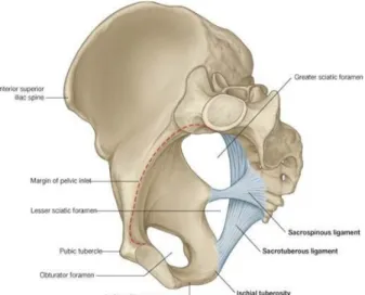
1.3.3 The ligament tension
Ligaments play an important role in body weight transmission act as strong mechanical beams. Two ligaments involve directly the acetabulum: the sacrospinous, the sacrotuberous ligament (Fig.9). The sacroiliac ligaments contribute to sacroiliac joint stability. Sacrospinous ligament is nearly horizontal in standing position and
doesn't contribute significantly in carrying loads in this condition. The most important ligament is the sacrotuberous one, which extends from ala of the sacrum downwards to the ischial tuberosity. Vertical loading produces a downward motion plus rotation. During normal standing, the upper body weight on the anterosuperior aspect of the sacrum produces an anterior sacral tilt which causes it to sink forward and downward. This potential motion puts the posterior sacroiliac, sacrotuberous and sacrospinous ligaments on stretch, which is an automatic locking device. [30]
1.4 Bone structure of the pelvis
Due to the complex forces pattern, pelvis presents a peculiar bone structure, in which trabeculae are oriented along the directions of the principal stresses and may be considered to represent the course of the stress trajectories. Moreover, modification of bone structure are due, also, as consequence of the remodelling theory proposed by Wolff [8]. This is the main reason of the anatomical differences between people in term of pelvic structure.
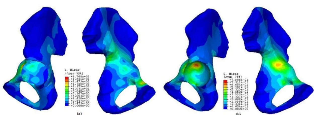
The pelvic bone mainly consists of trabecular bone covered by a thin layer of cortical bone forming a 'sandwich construction'. In this way, the bulk of the load is carried by and transferred through the cortical shell, while the trabecular bone act as a spacer, keeping the shells from collapsing [10]. The thickness of the cortical layer is directly coupled to its stiffness and load-transmitting capability, while transfer across a pelvic bone is relatively insensitive to changes in the material properties of the trabecular bone [9]. Stresses in cortical bone are higher than in the underlying trabecular bone [5] and the locations of the highest stresses in the cortical shell and the underlying trabecular bone, in general, don't coincide: in the cortical shell, in fact, the highest stresses are found in the attachment area of the gluteus major muscle and the incisura ischiadica major region, while in the trabecular bone, in the thin central area of the iliac wing and in the acetabulum. In and closely around the acetabulum, the highest stresses occur in the superior acetabular wall and from there they are transferred to either the sacro-iliac joint or the pubic symphysis (Fig. 7) .
Fig. 7: Stresses distribution over the hemipelvis: a) stresses in the cortical bone, b) stresses in the trabecular bone
A wide range of trabecular structures can be found: plate-like structures, more or less oriented perpendicular to the cortical shells, can be observed (Fig.8).
From a mechanical point of view, this is quite understandable because, as core material in a sandwich construction, pelvic trabecular bone will predominantly have to withstand shear-loading modes, against which a plate-like structure is the best resistance [10].
In the area under the acetabular joint surface the trabeculae were seen to emerge in a radiating pattern. A second system of trabeculae run at right angles to the one just described. They run concentrically around the acetabulum as a layer of thin shells which increase in thickness posteriorly where they run parallel to the corticalis.
The transfer of the hip force takes place predominantly in a narrow strip along
Fig. 8: Trabecular patterns of the os coxae interpreted as stress trajectories. Full lines represent compressive stresses, broken lines represent tensile stresses.
the anterior/superior edge of the acetabulum. The stress component which actually transfers the hip joint force onto the pelvic bone, is the normal or radially directed component of the contact stress between acetabulum and femoral head.
Because of this load transfer at the edge of the acetabulum, the lateral shell of the iliac cortex, just above the acetabulum and extending towards the incisura ischiadaca major region, is heavily stressed. To withstand these loads, density distribution of trabecular bone varies among pelvic regions: near the acetabulum it was found to be the highest and decreases in value moving away [8]. The highest densities can be found in the upper part of the acetabulum to the sacroiliac joint area and the middle part of the pubic bone, while the lowest densities in the ischial bone, as shown in Fig. 8 and Table 3.
Area Mean Ca-equivalent (g cm-3 ) St.Dev. Ca-equivalent (g cm-3 ) 1 0.09 0.02 2 0.17 0.03 3 0.10 0.04 4 0.14 0.03
Table 3: Density of trabecular bone distribution in the pelvis [10]
1.5 The total hip arthroplasty
Total hip Arthroplasty (THA) is the surgical replacement of the hip joint with an artificial prosthesis, needed when conventional medical therapy become poorly effective in treatment of a specific joint disease, causing chronic pain and disability for patients involved. This procedure, used for the first time in 1960s, consists in the excision of the femoral head and proximal neck and removal of the acetabular cartilage and subchondral bone in order to substitute them with mechanical components. [12]
Since the last decade THA has increased all over the world with differences depending on gender and age: women are, in general, more involved in hip surgery than men and, although an increase of younger people who undergoes hip surgery have been registered, elderly people aged 70 to 89 represent the most frequent patients for this kind of procedures, as shown in Fig. 10.
Fig. 10: Prevalence of total hip and knee arthroplasty in USA in 2010 (AOSS)
The most common cause for a first hip replacement is arthritis, consisting in a chronic inflammation of the hip join. This pathology can take place in different forms:
• Osteoarthritis: it consists in the wearing away of the cartilage cushioning the bones of the hip. The bones then rub against each other, causing hip pain and stiffness. Osteoarthritis may also be caused or accelerated by subtle irregularities in how the hip developed in childhood.
• Rheumatoid arthritis: it's an autoimmune disease in which the synovial membrane becomes inflamed and thickened. This chronic inflammation can damage the cartilage, leading to pain and stiffness.
• Post-traumatic arthritis: the cartilage may become damaged and lead to hip pain and stiffness over time, as consequence of a serious hip injury or fracture.
• Avascular necrosis: it's the consequence of an injury to the hip that limits the blood supply to the femoral head. The lack of blood may cause the surface of the bone to collapse, and arthritis will result. It can also be caused by specific diseases.
• Childhood hip disease: in this case arthritis derives from an irregular growth of the hip in children. Even tough a successful treatment of the specific bone pathology during childhood, arthritis may still occur, affecting the joint surfaces. [13]
Arthritis remains as the main indication for those procedures as the direct consequence of the population ageing, but many studies have found in increasing obesity, changes in criteria for selecting the patients for surgery, the development of better devices and materials, which allow THA to be increasingly performed in younger people, childhood diseases and hip fractures others possible factors for this increment. [16]
It is generally preferred that total hip arthroplasty be done in patients older than 60 years. The physical demands on the prosthesis tend to be reduced at these ages and the longevity of the operation approaches the life expectancy of the patient. However, in case of severe limitations of daily activities and persistent pain, the surgical approach is requested also for young patients.
Two different approaches can be performed for the surgical implantation: cemented (by the use of polymethilmethacrylate (PMMA)) or noncemented THA. The choice of the proper method, taken by the surgeon, generally, depends on physical patient's demand. In young, where a revision of implant is more likely and where the prosthesis is supposed to be more stressed, a noncemented approach is preferred, due to the need to avoid the generation of debris of cement in bone-prosthesis interface. Moreover, in youngs, the bone is more active hence, the osseointegration is facilitated. On the other hand, cemented components, guarantee a higher primary stability of the implant. Hence, several factors have to be considered.
1.5.1 The acetabular component
It consists in a hollow hemispherical device which substitute the acetabular region, acting as matching site for the femural head. It may consists in a whole block or, more commonly, in a modular block; in this case the device is composed by a metal back cup and bearing layer (high-molecular-weigth polyethylene (UHMWPE), ceramic, metal) articulating surface that acts as interface for the prosthesis with the femoral head. Nowadays, PE is generally preferred because it offers a good resistance to wear and reproduce well the cartilage behaviour in terms of reducing friction during load transfers in the hip joint [14]. The cup is inserted in the acetabular region by press-fitting and fixation to the pelvis is permitted by bone ingrowth into its outer porous metal
surface. Holes in the metal shell can be used to fix better the components in the bone wall with screws. Whole-PE acetabular component can be also found: fixation methods don't change but a metal circular wire in its upper part is requested for the radiological trace (Fig.11). In current practise, acetabular components are mostly uncemented.
1.5.2 The femoral component
It consists in a metal-alloy stem, inserted in the proximal medullary region of the femur and a modular cobalt-chrome or ceramic head that is fixed to the neck portion of the femoral stem by interference fit. The stem is inserted by press-fit without the need of the cement or with cement. In case of uncemented approach, the stem may present a porous surface in its wide part as help for the “biological fixation” (Fig.12). Generally, with a noncemented total hip arthroplasty, a more exact surgical insertion technique is requested because maximum contact between prosthesis and bone must be achieved.
1.5.3 Resurfacing implant
Resurfacing arthroplasty is an alternative method to the most conventional total hip replacement and is a bone preserving
approach consisting on the placing of a metal (CrCo alloy) hollow cup over the head of the femur and matching it with a metal acetabular cup (Fig.13). Femoral head has to be previously trimmed and cement is needed for the fixation. Advantages in performing a resurfacing implant are: less bone removal and a consequent easier revision check, and the
decreased risk of dislocation due the larger head size (similar to the patient's one). Between the disadvantages the femoral neck fracture and shed of metal particles can be found. Resurfacing implant are typically made in young in which stress demand is higher as well as the probability of a future revision replacement. [29][30]
Fig. 13: Resurfacing implant Fig. 12: Femoral component: stem with ceramic head (left), stem with metal head (center), porous stem (right)
1.6 Aim of the thesis
The aim of the present work is to give an exhaustive overview of the acetabular region of the pelvis and problems involving it focusing in particular on:
1. collecting data from the most reliable world registries relying on hip revision arthroplasties;
2. selecting most suitable classification of the acetabular defects in order to be able to reproduce them in future biomechanical tests;
3. defining a systematic approach for in vitro mechanical testing of human pelvic specimens, consisting, firstly, in the definition of a reproducible reference frame for human pelvis and hemipelvis, and, secondly, in the creation of a protocol for the alignment of hemipelvic specimens in the testing machine in a physiological way.
Chapter 2
Critical analysis of worldwide registries
of revision total hip arthroplasty
Chapter 2 describes the main causes which allow the revision of the hip joint implant. After a brief definition of the causes, a review of national registers is presented. For this purpose information from the most updated registries has been chosen in order to define the most common causes provoking a replacement of the previous devices. Registers from USA, Great Britain and Nordic countries have been studied as well as the regional register of Emilia Romagna (Italy).
2.1 Failure of the prosthesis: the revision THA
Arthroplasty surgery has been shown to be an effective intervention to improve pain, function and quality of life in people with severe joint disease of the hip. [15] However, when the failure of a previously implanted prosthesis occurs, a revision needs to be carried out: in this case the surgical operation is called Revised Total Hip Arthroplasty (RTHA).
Failure is a simple term that gathers a great number of problems which may involve the hip joint region. These problems may have a mechanical and/or a biological nature and may lead to a displacement of the current implantation and pain for the patient. Prosthesis stability is the main aim of the surgeon and failure of the implant in the short-term period is a consequence of intraoperative errors and/or body reject. Long-term failure phenomenons derives from mechanical causes like wear, fatigue and may be linked to aseptic loosening and osteolysis. In each cases, all cement and prosthetic components are removed carefully to
avoid penetrating or fracturing the bone and then new components are implanted and fixed. That' s the reason why RTHAs are generally more difficult than the primary THA, from a technical point of view. [12]
2.1.1 Aseptic loosening
Aseptic loosening is a multi-factorial event resulting in mobilization of the implant [21], that occurs when tiny particles are generated in the closest acetabular region. Several studies have demonstrated that the presence of micrometer or nanometer debris around the implant produces a series of chemical and physical reactions which progressively lead to the failure of the prosthesis. Debris may belong to cement used for the fixation of the implant, to the bone or to the prosthesis itself (bearing), and the localization in situ of these particles can be the result of inadequate initial
fixation, mechanical loss of fixation over time, or biologic loss of fixation caused by particle-induced osteolysis around the implant, micromotion between surfaces, oxidative reactions, inappropriate mechanical load and stress shielding and minor pathogen contaminations. [22][23] In general, the initial response is a localized anti-inflammatory response that is characterized by formation of
fibrous tissue that encapsulates the implant. Particles are phagocytosed by
Fig. 14: Aseptic loosening: black arrows indicate the sites affected by bone debridement
macrophages which try to engulf and digest the particles that are seen as 'foreign' to the body. They act in two major ways in the bone remodelling process: firstly, they release different cytokines involved in bone remodelling, which modulate osteoblast and osteoclast activity with a direct increase of osteolysis. Secondly, macrophages may differentiate into osteoclasts affecting the bone tissue directly. [21]
This process starts an unstable loop which progressively leads the failure of the implant and the need of the hip surgery revision.
2.1.2 Periprosthetic acetabular fractures
Periprosthetic fractures of acetabulum are rare (in contrast to those of the femur) but potentially disastrous complications in primary and, mostly, revision arthroplasty. Due to their aetiology they can be classified as peri-operative and post-operative fractures.
Peri-operative fractures occur during the implant of a (typically) uncemented prosthesys or during the removing of an extent one in a revision surgical operation. Several causes can be detected leading this kind of injuries:
• type of acetabular shell • excessive reaming
• pathological processes (primarly osteoporosis, rheumatoid arthritis, Paget's disease) [24]
Post-operative fractures can be differentiated in acute traumatic and chronic periprosthetic fractures.Traumatic fracture consists in a bone fracture caused by an unexpected stress peak which directly involves acetabulum or its close bone region, transmitted by the femoral head; the type of fracture depends on hip
position at the moment of the trauma and on the direction and energy of the impact. [25]
Chronic periprosthetic fractures lead to bone loss of the acetabulum with the consequent dissociation of superior and inferior parts of the hemipelvis (pelvis's discontinuity) and may be caused by several factors like osteolysis, infection, chronic migration of the socket and iatrogenic bone loss during component removal in revision arthroplasty.[26]
2.1.3 Dislocation
Dislocation occurs when the femoral head comes out of the cup-shaped acetabulum set in the pelvis.and is usually caused by high-energy trauma, such as road traffic accidents or fall from heights, that may provoke the femoral head's disjunction posteriorly or anteriorly.
• Posterior dislocation: it takes place in most cases. The thigh bone is pushed out of the socket in a backwards direction. A posterior dislocation leaves the lower leg in a fixed position, with the knee and foot rotated in
Fig. 15: Periprosthetic acetabular fracture: red line surrounds the injured site
toward the middle of the body. • Anterior dislocation: in
this case the thigh bone slips out of its socket in a forward direction, with the hip slightly bent, and the leg rotated out and away from the middle of the body.
When the hip dislocates, the ligaments, the labrum, muscles,
nerves and other soft tissues holding the bones in place may be injured, as well. [27]
In the literature, a few cases of atraumatic dislocation of the hip joint can be found: it's a rare case of dislocation in which the separation between femoral head and acetabulum is caused by normal stress. Among the causes, anterior capsule insufficiency, small center-edge angles, developmental dysplasia and laxity of ligaments may be included. [28] Among THA patients atraumatic dislocation occurs when the relative movement range between the articular components is exceeded (crossing the legs, sitting down,....).
2.1.4 Infection
Infection is caused by the presence of bacteria in the hip joint site that provoke an inflammatory reaction which damages local soft tissues.
Infectious agents may reach the joint:
Fig. 16: Anterior dislocation of a hip joint prosthesis
• directly as consequence of traumas, surgical implant or injection • as extension of a close infection
• because of their diffusion in the synovial tissue, taken from a distant site by means of the hematic flow [32]
In the literature several classification of infection reactions can be found. Following the classification system proposed by Coventry (1975) and modified by Tsukayama et al. (1996) is proposed:
Stages Description
I Infections occurring acutely within six weeks of implantation II Infections being delayed chronic presentations
III Infections occurring in a previously well functioning joint replacement
IV Infections being unexpected positive culture results in what was thought to be an aseptic revision
Table 4: Classification system for articular infection in THA [33]
2.2 Revision THA in the world
Informations about revision of hip replacement in Europe are gathered in the European Arthroplasty Register (EAR). For the aim of this work revised data have been taken from reports available on EAR website. The choice of European countries has been made considering the number of patients and the reliability of the data. Basing on these two aspects the following registries have been considered:
• the National Joint Registry (NJR) for England, Wales, Ireland and the Isle of Man (Annual Report 2015)
informations from Sweden, Norway and Denmark (2009)
USA lack of a national register for hip arthroplasty, however, because of the large population, it has been decided to use available data (Bozic et al.,2009) for the purpose of a large retrospective study.
As shown in Table 5, the most common causes can be identified in aseptic loosening, dislocation of the prosthesis and infection, with a general uniform trend for all countries. Other factors, like periprosthetic fractures, implant breakage, technical errors and pain, have been shown to be potential causes for a RTHA. [17][18][19] USA 51345 pat. Oct.2005-Dec.2006 England 79859 pat. Apr.2003-Dec.2014 Denmark 3006 pat. 1995-2006 Sweden 4001 pat. 1995-2006 Norway 2554 pat. 1995-2006 Aseptic Loosening 19.7 % 24.4 % 34.8 % 50.4 % 47.3 % Instability/ Dislocation 22.5 % 16.9 % 33.5 % 23.4 % 23.8 % Infection 14.8 % 13.6 % 15.8 % 15.0 % 15.5 %
Table 5: the table shows the main causes of failure of THA. Under each country the number of patients and the period in which the revision surgery treatment has been performed are reported.
2.3 Revision THA in Italy
Italy doesn't have a national register. So far, an effort to collect data from different regions has been made and the RIAP (Registro Italiano Artro Protesi) has recently been created. It represents an attempt for Italy to uniform with other European countries with the purpose of allowing free exchanges of informations. Because of the lacking of collective data yet, for the purpose of the current study, data from RIPO (Registro Implantologia Protesica Ortopedica) of Emilia
Romagna have been adopted.
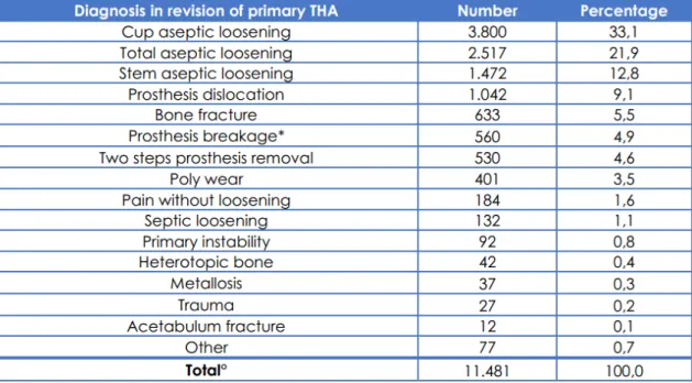
Data shown in Table 4 represent the number of revision operations carried out on patients admitted between 1st January 2000 and 31st December 2013 according to diagnosis.
In line with Table 5, the most common cause of failure for primary THA is represented by the aseptic loosening. [20]
Excluding joint dislocation, generally, all the causes of hip damages determine the loss of material in and/or around the joint. Lack of bone or lack of components of the devices (induced by wear) aims to a gradual loss of joint functionality. Lock of bone, in particular, drain the region of supportive structures and lower the stability of the implant. Moreover, during the revision, the removal of the damaged implant may create new local defects (removal of the screws, detach of the cup,...) that have to be considered by the surgeon before the
Table 6: Causes of failure of primary THA. (º 133 missing data (1.1%); * Failure of 189 modular necks, 126 liners, 94 heads, 72 stems, 65 cups. 14 failure not specified)
operation, in terms of bone reconstruction and type of device. Typical strategies and material of bone and component reconstruction (acetabular) are described in chapter 3.
Chapter 3
Critical analysis of bone defects
classifications and treatment
In chapter 3 a review of the most used classifications of bone defects are proposed. Criteria of selection derive from a critical analysis of several works dealing with bone loss and the evaluation of repeatability of the methods proposed. For a more complete review of the damage classifications involving the pelvis, analysis have been performed both on acetabular defects and pelvic fractures. Because of all these criteria also depend on radiological features, a general overview of the main parameters useful for the surgeon in a preliminary estimation of pelvic conditions are presented. Finally, a general overview of the technique used for the bone reconstruction is proposed: these methods represent the most important part of the surgical operation before the implant of the new prosthetic device.
3.1 Radiological landmarks
Reference planes cover an important role also for surgeon's evaluation of bone defects.
Beside the conventional anatomic description of hip and acetabular bones surgeons adopt an operative description of bone features in order to evaluate bone defects or structure diseases, based on the radiographs. In the following, a list of typical parameters is presented, involving acetabulum only; they are used in several classifications of acetabular defects and help the surgeon in the choice of the proper surgical approach and implantation.
• ilioischial line (Kohler's line): it begins at the medial border of the iliac wing and extends along the medial border of the ischium to end at the ischial tuberosity. This defines the posterior column of the pelvis [34]; • ileopectineal line: it extends from the medial border of the iliac wing,
along the superior border of the superior pubic ramus to end at the pubic symphysis. This line is seen as the inner margin of the pelvic ring and defines the anterior column of the pelvis [34];
• teardrop: it results from the end-on projection of a bony ridge running along the floor of the acetabular fossa [35]. Teardrop distance is measured from the lateral edge of the teardrop and the femoral head (Waldenström sign). Side-to-side comparison of the teardrop distance can be useful to evaluate for hip joint effusion or for hip dysplasia [34];
• Hilgenreiner line: a line formed by a horizontal line connecting both triradiate cartilages [35];
• Perkin line: a line drawn perpendicular to Hilgenreiner line, intersecting the lateral most aspect of the acetabular roof. The the upper femoral epiphysis should be seen in the inferomedial quadrant: it should lie below Hilgenreiner line, and medial to Perkin line [35];
• Tönnis angle: an angle used to evaluate acetabular inclination. A line is drawn connecting the inferior aspect of the left and right-sided acetabular teardrops. A second line, parallel to the first, is drawn through the inferior aspect of the acetabular sourcil. Lastly, a line connecting the inferior and lateral aspects of the acetabular sourcil is drawn. The angle created by the intersection of lines 2 and 3 (the Tönnis angle) should be between 0° and 10° [36];
• Sharp's angle: the angle formed by a line connecting the lateral acetabular sourcil and inferior aspect of the pelvic teardrop and the horizontal line between the inferior aspect of both pelvic teardrops [10];
• Sacral slope: an angle used for the evaluation of pelvic tilt and is generated by a horizontal line and a line tangent to the sacral plate.
• Pelvic incidence: the angle formed by a line connecting the midpoint of the sacral plate with the axis of the femoral head and a line perpendicular to the sacral plate [37].
• Pelvic tilt: the angle formed by a vertical line and a line connecting the centre of femoral head and the mid point of the sacral plate
Following pictures of some of the features previously defined are shown.
Fig. 17: Radiographic features get from a frontal radiographic view. a) Kohler's line (blue), ileopectineal line (yellow); b) teardrop (yellow), Hilgenreiner line (blue), Perkin line (orange); c) Tonnis's angle (yellow), Sharp angle (blue)
3.2 Acetabular bone loss classifications
Surgical approach for a revision hip arthroplasty depends on different factors like surgeon experience, additional exposure, presence of distorted anatomy, patient factors and degree and location of bone defects. [38] The last one, in particular, is the most significant factor for surgeon in planning joint functional reconstruction (surgical access paths, choice of the device) and over the years attempts in drawing up a reliable classification of bone defects associated with loose hip implants have been made; the aim is helping surgeons in the preoperative planning with a shared, practical method for an evaluation of surgical complexity. Furthermore, classifications help to promote the uniform measurement and reporting of surgical results.
Several classifications have been proposed over the years, which differs in the grading scale progressing from mild to severe defects and relies on the quantity of bone remaining in and around the acetabulum before a surgical revision. In the following, a review of several bone classification systems is proposed. The choice of the classification systems, principally, relies on their use worldwide and
on their repeatability evaluated for a single operator and between operators.
3.2.1 Paprosky classificaion
Paprosky classification is a functional classification, based on the presence or absence of supporting structures such as the acetabular rim, superior dome, medial wall, anterior and posterior columns and the surgeon's assessment of these structures capacity to support the revision prosthesis [39]. The following table and figure show the grading scale for acetabular defects.
In order to have a visualization of the bone defect, a graphic 3D reconstruction is also presented.
Based on the structures predicted to be deficient, and the degree of hip centre migration, Paprosky offers recommendations regarding the type and amount of supplemental allograft needed for reconstruction methods of graft fixation and implant selection. [40] Type 1 defects had bone lysis around cement anchor sites and required particulate graft. Type 2A and B defects displayed progressive bone loss superiorly and required particulate graft, femoral head bulk graft, or cup superiorization. Type 2C defects required medial wall repair with wafer femoral head graft. Type 3A and B defects demonstrated progressive amounts of superior rim deficiencies and were treated with structural distal femur or proximal tibia allograft [43] (Table 8). For Paprosky's type I, IIA and IIB defects and, in general, for patients who have not shown evidence of hip center migration or pelvic discontonuity hemispherical revision implants are acceptable, either with or without cement or porous coat. Type IIC, IIIA and IIIB generally require antiprotrusio cages in order to increase the contact area between the bone host
Fig. 19: Picture of Paprosky's classification: A) Type 1; B) Type 2A; C) Type 2B; D) Type 2C; E) Type 3A; F) Type 3B [40]
and the device. [44]
3.2.2 D'Antonio classification
This classification is the current system adopted in the American Academy of Orthopaedic Surgeons (AAOS). It distinguish between segmental and cavitary defects, defining five levels for the acetabular abnormalities.
Both Paprosky's and D'Antonio's classification require preoperative standard AP
Table 9: D'Antonio classification [39] Table 8: Paprosky's acetabular adjuncts [40]
and lateral radiographs (as well as CT scans in case of severe injuries) for the evaluation of the damage entity. Despite of the surgical approach suggested by the preoperative evaluation, only intraoperative estimation of the defects will lead surgeon to the proper operational approach; furthermore, a study by Campbell et al. (2001), showed their limited reliability in terms of intra- and inter- operator repeatability. For these reasons these systems should be considered only as a general guide for treatment options [41].
3.2.3 Saleh classification
Between the several classification methods proposed in literature, statistical analisys (k analisys) made by Johanson et al. (2010) proved that Saleh classification represents the only classification method which has been shown to
have a good interobserver reliability. It relies on information extracted from plain radiographs [42][39]. The reasons why surgeons generally prefer to perform other kind of classifications can be probably find in the fact that a worldwide shared method, like Paprosky's one, may allow to get shareable results.
Like Paprosky's also Saleh's classification suggests operative surgery approach depending on the acetabular conditions.
3.3 Periprosthetic acetabular fractures
These kind of fractures derives from great stresses (stumbling, falls,...) that accidentally occur in operated patients with compromised bone quality, that reflect on the pelvis. The injury generally starts in a region close to the prosthesis and may involve the whole hemipelvis. Pathological factors, like osteoarthritis, may increase the extension of the damage.
3.3.1 Judet-Letournel classification
It's the first classification for acetabular fractures ever made and distinguishes between 5 elementary fractures and 5 comminuted fractures, dependently on the interested column or acetabular wall [25].
Evaluation of both simple and associated fracture types is made by mean of AP and lateral radiographies as well as CT scans.
3.3.2 Paprosky classification
This is the most widely used classification system and determines all known variants of periprosthetic acetabular fractures; Based on the clinical presentation, it allows specific treatment options.[26]
Fig. 20: Judet-Letournel classification: A) Posterior wall, B) Posterior column, C) Anterior wall, D) Anterior column, E) Transverse, F) Posterior olumn and posterior wall, G) Transverse and posterior wall, H) T-shape, I) Anterior column and posterior hemi-transverse, J) Two columns
3.3.3 Unified classification system (UCS)
Introduced in 2014, it expands to anatomical aspects and location of the fracture. It consists of a numeric code that describes the affected joint as well as the involved bone corresponding to the principles of fracture classification of the Association for the Study of Internal Fixation (ASIF). Each joint is related to a number, proceeding from the shoulder (I), elbow (II), wrist (III), hip (IV), knee (V) and ankle (VI); for each joint, bone involved are classified with a number too (i.e. pelvis:6) [26].
Type A is a fracture of an apophysis or protuberance of bone, to which one or more soft-tissue structures are attached. Type B involves the bed-supporting or adjacent to an implant (B1 the implant is still well fixed; B2 the implant is loose; B3 the implant is loose and the bone bed is of poor quality because of osteolysis, osteoporosis, or comminution). This sub-classification is fundamental to the original Vancouver Classification System. Type C involves a fracture which is in the bone containing the implant, but distant from the bed of the implant. Type D is a fracture affecting one bone, which supports two replacements. Type E involves two bones supporting one replacement. Type F is an uncommon fracture involving a joint surface, which is not resurfaced or replaced, but is directly articulating with an implant.[26]
3.4 Devices for acetabular revision
Once identified the acetabular defects, the proper revision device has to be chosen, depending on the quantity of bone stock loss, the entity of the defect, the patient characteristics, the ability of the columns to support biologic fixation and the presence of discontinuity.
The aim of revision acetabular reconstruction is to obtain a stable fixation and restore the hip center. [44]
In table 12the typical revision options for the acetabular component are presented.
3.5 Bone reconstruction
Bone loss is is the most important defect to consider before performing a revision THA, because the lack of bone tissue compromises the local structural properties, preventing the primary stability of the implant.
For this purpose the restoration of a functional base for the fixation of the new implant is necessary and nowadays several techniques can be adopted by the surgeon, depending on the quantity of bone lack.
Autologous bone grafting represents the 'gold standard' between the surgical procedure for bone reconstruction thanks to its properties of osteoinduction, osteogenesis and osteoconduction. It consists in the transplant of bone tissue from one part of the body to another in the same person. In case of large bone defects, in order to provide for the higher amount of bone tissue needed, an alternative to the autograft is the allogeneic bone grafting, in which the bone tissue derives from demineralised bone matrix, morcellised and cancellous chips, corticocancellous and cortical grafts, osteochondral and whole-bone segments obtained from a human cadaver or a living donator. Despite the devitalization of the allografts (which determines the reduction of osteoinductive properties) rejection reactions and infection cannot be excluded.
Scaffolds of synthetic or natural biomaterials represent a good alternative to bone-graft materials, becoming more and more used in clinical practice for osteoconduction, as bone-graft extenders or sobstitutes. Typical materials for scaffolds are collagen, hydroxyapatite, calcium-phosphate cements but also metal alloys like titanium in combination with cancellous bone, autologous bone or bone matrix.
bone morphogenetic proteins (BMPs) or platelet-rich plasma of autologous blood, that induce mitogenesis of mesenchymal stem cells and, hence, accelerating the bone repair.
A rising strategy for bone reconstruction is represented by the tissue engineering, consisting in creating bone tissue from autologous progenitor or mature cells seeded in biocompatible and/or bioabsorbable three-dimensional structures with growth factors, in order to obtain osteoinduction and vascular ingrowth. [45]
Chapter 4
Reference frames for human pelvis and
hemipelvis
The aim of chapter 4 is to define a reproducible reference frame for in vitro testing on human hemipelvic specimens. After a review of the most common reference systems for these kind of specimens findable in the literature, a practical method is presented. It relies on anatomical landmarks and angles identifiable on the pelvis and has the purpose of helping operators in fix the specimen in the testing machine in a physiological position. Both the original and the improved version of the method are presented as well as statistical analysis that prove the good inter-and intra-repeatability of the technique.
4.1 Clinical applications
Reference frames and landmarks for the pelvic bone can be adopted for different applications.
• Originarly, they have been defined for clinical imaging with the aim to assess the surgeon in diagnosis of the bone hip defects and prosthesis implantation.
• With the advent of better visualization tools their use has been extended for in silico numerical simulations with the purpose of study the pelvic bone mechanical behaviour with mathematical models;
reference frames for movement analysis.
4.2 In vitro vs in silico applications
Biomechanical tests are useful to discover the mechanical properties of biological specimens. Two ways can be adopted for this purpose: the traditional in vitro test, in which specimens are physically stressed and in silico tests that use mathematical simulations (e.g. finite element models) to obtain mechanical informations.
Both the methods have positive aspects to be considered and the preference of one of the two is related to the type of informations of interest.
In silico applications allow to obtain detailed data on a large population in a fast
and economic way. However, the accuracy depends on the mathematical equations adopted for the simulations like constitutive equations, finite element models, boundary conditions and solving methods, and, because of this reason, results are just an approximation of the real informations.
In vitro applications better reproduce the mechanical behaviour of the specimen
of interest, because loads applied are real and, generally, reproduce physiological stress conditions. High costs (machines and biological specimens) and long duration of the testing period represent the main limitations of these techniques. Reference frames are necessary when you have to perform studies based on directions of loads and movement, with the aim of define a shared system for data and results.
They rely on anatomical landmarks that can be easily identified in vivo on the pelvis and, depending on the application, may widely differ in terms of
landmarks, and consequently of planes, adopted. X-ray and CT-scans allow to obtain precise reconstructions of pelvis suitable for ad hoc in silico studies or for generating a mathematical model.
4.3 Commonly used reference frames for in silico
applications
4.3.1 Anterior Pelvic Plane (APP)
The anterior pelvic plane, also called the Lewinnek plane, is commonly used as the reference plane to guide imageless computer assisted surgery for THA in cup orientation and is generally considered to be globally vertical in the standing position [46]. Once identified the
two anterior superior iliac spines (ASIS) and the most anterior tubercle APP is defined as the plane derived from these points and correspond to the coronal plane (APPCor). Definition of the other two reference planes is as follows: a plane parallel to ASIS line and orthogonal to plane APPCor is
drawn to give an axial plane (APPAx). These two planes, together with a sagittal plane (APPSag) which is orthogonal to both form the APP coordinate system [47]. The centre of APP can be chosen arbitrarily, in example in the centre of the hip joint.
4.3.2 Transverse Pelvic Plane (TPP)
Once identified one anterior superior pelvic spine, the correspondent pubic tubercle and the posterior superior pelvic spines (PSPS (Fig. 23)), the plane derived from the first two points and the PSPS of the same pelvic side is defined as Transverse Pelvic Plane (TPPAx). Definition of the other two reference planes is as follows: the plane orthogonal to TPPAx and to PSPSs line is the sagittal plane (TPPSag). The coronal plane (TPPCor) is parallel to PSPS line and is perpendicular to both TPPAx and TPPSag [47].
4.3.3 Standardization and Terminology Committee (STC) of the International Society of Biomechanics (ISB) reference planes
The STC plane is used as a reference plane for hip joint motion. [48] O: The origin coincident with the right (or left) hip centre of rotation.
Z: The line parallel to a line connecting the right and left ASISs, and pointing to the right.
X: The line parallel to a line lying in the plane defined by the two ASISs and the midpoint of the two PSISs, orthogonal to the Z-axis, and pointing anteriorly.
Y: The line perpendicular to both X and Z, pointing cranially.
The centre of the coordinate system
is defined at the hip centre of rotation. [49]
4.4 Review of reference frames for in vitro applications
Defining a pelvic reference frame is necessary in biomechanical trials and in
vitro experiments in order to enhance the alignment of specimens in the testing
machine.
The alignment of the specimens is the first step for in vitro biomechanical testing and depending on the reference frame adopted, it is important to define a repeatable and reproducible reference frame. Unfortunately, although alignment protocols have been made for in vitro experiments for femur and vertebra [50, 51], in the literature, practical methods for the human hemipelvis have not been defined. The few previous works dealing with hemipelvic specimen lack of details about its alignment: Lewton (2015) [3] specified the direction of application loads, defined as angles measured relative to the long axis of the pelvis but none reference frames have been defined. Preece et al. (2008) [53] proposed a practical method in line with the anatomical neutral position suggested by Kendall and Mc Creary in which both ASISs were aligned horizontally and the pubic symphysis and ASISs were in the same vertical plane; however clear informations about the alignment method have not been shared [46][54]. Moreover, the study, as most studies presented in literature in which anatomical reference frame have been defined [47][48][49], dealt with the entire pelvic bone, while in our study we tested the half left side of human pelvis only. Hence a new practical approach has to be defined. The main aim of this work was to provide a portable definition for a reproducible alignment method for the human hemipelvis, suitable for in vitro applications, based on robust anatomical landmarks and physiological angles.
For the aim of the present study a reference frame based on the Anterior Pelvic Plane has been adopted and adapted to be used for hemipelvic specimens.
Despite its debated reliability in surgical implantation [55], for our purpose it represents just an easy reproducible and repeatable plane to define an anatomical reference frame:
• based on clear anatomical landmarks; • widely used all over the world;
4.5 In vitro identification of anatomical features and
angles on the entire pelvis
4.5.1 Definition of the reference frame
For the aim of the present study the reference system adopted has been inspired by Dandachli et al. (2006), composed by the APP and its derived orthogonal planes, partially modified for being used in in vitro applications.
4.5.2 Identification of the landmarks
Three landmarks has been used for the study (Fig. 24):
• ASIS (Anterior Superior Iliac Spine): most prominent point on the external iliac surface;
• PSIS (Posterior Superior Iliac Spine): upper and most prominent projection on the posterior border of the iliac wing;
• PT (Pubic Tubercle): most medial point on the extension of inner line of upper oval foramen.
4.5.3 Material and methods