Scuola Dottorale di Ingegneria
Sezione di Ingegneria dell’Elettronica Biomedica, dell’Elettromagnetismo e delle Telecomunicazioni
XXVIII ciclo
Next Generation Optical High-Speed
Network
Tesi sottomessa
all’Università degli studi Roma Tre per il conseguimento del titolo
DOTTORE DI RICERCA
Giugno 2016Dottorando: Julian Hoxha
Docente Guida: Prof. Gabriella Cincotti
iii
The research ‘Next generation optical high speed networks’ considers new paradigms for optical access and long-haul (1000 km and above) communications, to satisfy the increasing demand for capacity, spectral efficiency and quality of service in telecom networks. In long-haul transmissions, digital signal processing (DSP), with high-order modulation and coherent detection, has revolutionized optical systems, thanks to its effectiveness to digitally mitigate chromatic dispersion and polarization mode dispersion, with an increase in transmission length. However, the drastic increase in system complexity creates a severe challenges for real-time implementation, related also to limited bandwidth of digital to analog converters (DAC), high power consumption of electronic devices, massive use of hardware parallelization and pipeline, making the system intolerant to any feedback path. On the other hand, future access optical passive networks (PON) need to increase per-user bandwidth, evolving towards wavelength-division multiplexing (WDM) systems, with colourless (wavelength independent) low-cost transmitters at the user’s side, also allowing different operators to share the same infrastructure. For both core and access networks, orthogonal frequency division multiplexing (OFDM) is proposed to overcome the electronic bottleneck, reduce power consumption and increase the spectral efficiency, satisfying current large bandwidth requests.
During the three-year research work, within the EU ASTRON and the Italian ROAD-NGN projects, new optical network architectures, systems and subsystems have been proposed and their performances have been analytically, numerically and experimentally evaluated.
In particular, new digital OFDM systems for unbundling the local loop (ULL) in access networks have been investigated for ultra-high speed PONs, along with
discrete multitoned (DMT) approaches, based on reflective semiconductor optical amplifier (RSOA).
All optical OFDM (AO-OFDM) systems have been experimentally tested during a 6-month staying at the National Institute of Information and Communications Technology (NICT) in Japan, using both coherent and direct detection receivers. The performance of two different optical devices, able to demultiplex the AO-OFDM signal, have been experimentally compared, without optical dispersion compensation or time gating.
For long haul transmissions, AO-OFDM can also reduce the power consumption in case of superchannels, with a high number of sub-channels. Analytically formula have been found for performance evaluation, in terms of maximum number of spans, frequency offset, phase noise and equalization enhancement phase noise (EEPN), supported and validated by numerical simulation.
Finally, a novel transmission system is proposed, based on the digital fractional Fourier transform, to generate sinc-shaped time domain pulse at the receiver side, reducing the DSP complexity for real time implementation at high data rates.
SOMARIO
Il tema di ricerca ‘Reti ottiche di nuova generazione ad alta velocità’ considera nuovi paradigmi sia per l'accesso ottico che per le trasmissioni a lungo raggio (più di 1000 km), per soddisfare la crescente richiesta di capacità, efficienza spettrale e qualità del servizio nelle reti di telecomunicazione. Nelle trasmissioni a lungo raggio, il processamento del segnale nel dominio digitale, l’utilizzo delle modulazioni complesse e la rivelazione coerente, hanno rivoluzionato i sistemi ottici grazie alla loro efficacia di compensare digitalmente la dispersione cromatica e da polarizzazione, con un aumento della lunghezza di trasmissione. Tuttavia, il drastico aumento della complessità crea delle difficoltà per l’implementazione in tempo reale. Questo è dovuto alla banda limitata dei convertitori digitale analogico (DAC), ad un elevato consumo energetico dei dispositivi elettronici, a un uso massiccio di parallelizzazione hardware, rendendo il sistema intollerante a qualsiasi percorso di controreazione.
D'altra parte, le future rete d’accesso ottiche passive devono aumentare la velocita di cifra per utente, evolvendo verso sistemi di multiplazione a divisone di lunghezza d’onda, utilizzando trasmettitori economici e indipendenti dalla lunghezza d’onda al lato dell'utente, consentendo anche ai diversi operatori di condividere la stessa infrastruttura. Per entrambe le reti di trasporto e di accesso, la multiplazione ortogonale a divisione di frequenza ortogonale (OFDM), permette di superare il ‘collo di bottiglia’ dovuto all’elettronica, ridurre il consumo energetico e aumentare l'efficienza spettrale, soddisfacendo le richieste di banda.
Durante il lavoro di ricerca di tre anni, nell'ambito dei progetti ROAD-NGN e ASTRON, sono state proposte nuove architetture, sistemi e sottosistemi in una rete ottica, valutando le loro prestazioni, analiticamente, numericamente e anche sperimentalmente.
In particolare, i nuovi sistemi OFDM digitali per la disaggregazione dell'ultimo tratto nelle reti di accesso sono stati accuratamente studiati ad alta velocità di cifra utilizzando la tecnica DMT e un amplificatore ottico a semiconduttore riflettente (RSOA).
I sistemi tutto-ottici OFDM (AO-OFDM) sono stati valutati sperimentalmente presso National Institute of Information and Communications Technology (NICT) in Giappone
utilizzando ricevitori coerenti e diretti. Sono state valutati sperimentalmente le prestazioni di due dispositivi ottici in grado di demultiplare il segnale AO-OFDM senza compensazione della dispersione ottica o campionando otticamente.
AO-OFDM può ridurre il consumo di energia nelle reti di trasporto utilizzando dei ‘Supercanali’ costituito da un elevato numero di sottoportanti. Sono state trovate formule analitiche per la valutazione delle prestazioni, in termini di numero massimo di span (1 span è lungo 80km di fibra), offset di frequenza, rumore di fase e rumore di fase originato dalla dispersione cromatica non-equalizzata. I risultati ottenuti sono stati validati da simulazioni numeriche.
Infine, è stato proposto un nuovo sistema di trasmissione multi-portante basato sulla trasformata frazionaria di Fourier digitale in grado di generare degli impulsi sinc nel tempo al lato ricevente sfruttando l’effetto della dispersione cromatica. La complessità degli algoritmi al lato ricevente è stato ridotto drasticamente redendo cosi possibile l’implementazione in tempo reale del sistema a una velocita di cifra elevata.
vii
ABSTRACT ... iii
SOMARIO ... v
ACKNOWLEDGEMENTS ... xi
LIST OF FIGURES ... xiii
... 1
CHAPTER 1 EVOLUTION OF OPTICAL FIBER COMMUNICATION ... 1
1.1 Motivations ... 1
1.2 Evolution of optical transport networks ... 2
1.3 Evolution of optical access networks ... 5
1.4 High-speed single carrier and multicarrier transmission ... 6
1.4.1 Single carrier trasmission ... 7
1.4.2 Multicarrier transmission ... 8
1.5 Thesis outline and contributions ... 11
1.5.1 List of publications ... 13
References ... 15
... 17
CHAPTER 2 OPTICAL ACCESS NETWORKS BASED ON ELECTRICAL OFDM ... 17
2.1 Introduction ... 17
2.1.1 Electrical OFDM with optical modulation ... 18
2.1.1.1 IM/DD ... 18
2.2 OFDM ... 20
2.3 Electrical OFDM for PONs ... 24
2.3.1 Unbundling the local loop ... 25
2.3.2 OFDM-PON based on IM/DD for ULL ... 26
2.3.3 Performance evaluation ... 29
2.4 Access networks based on RSOA ... 31
2.4.1 RSOA model ... 34
2.4.2 Bit and power loading ... 37
2.4.2.1 Water filling algorithm ... 39
2.4.2.2 Levin-Campello algorithm ... 41 2.4.3 RSOA characterization ... 42 2.4.4 Performance evaluation ... 46 2.5 Conclusions ... 50 References ... 51 ... 56 CHAPTER 3 ALL OPTICAL OFDM ... 56
3.1 Introduction ... 57
3.2 Principle of operation ... 58
3.2.1 Cyclic prefix in AO-OFDM setup ... 67
3.3 Direct detection ... 69
3.3.1 DPSK modulation ... 70
3.3.1.1 Simulation results for DPSK ... 72
3.3.2 DQSK modulation ... 75
3.3.2.1 Simulation results for DQPSK ... 76
3.4.1 Coherent setup ... 78
3.4.1.1 Model with frequency offset and phase noise ... 80
3.4.1.2 Frequency offset due to AWG and TX comb ... 81
3.4.1.3 Phase noise and EEPN investigation ... 83
3.4.1.4 Joint FFCPE investigation ... 87
3.4.1.5 Bandwidth and sampling rate requirements ... 88
3.4.1.6 Frequency domain equalizer and power consumption estimation ... 89
3.4.1.7 Nonlinear performance ... 90
3.5 Experimental results ... 92
3.5.1 Flat optical comb generation ... 95
3.5.2 Experimental performance evaluation ... 101
3.5.3 Experimental comparison between FBG and an AWG ... 104
3.6 Conclusions ... 106
References ... 108
... 112
CHAPTER 4 OFDM BASED ON THE FRACTIONAL FOURIER TRANSFORM ... 112
4.1 Continues fractional Fourier transform ... 113
4.2 FrFT and the time lens effect ... 117
4.3 Implementation of digital FrFT ... 121
4.4 Coherent optical communications based on PM-FrFT ... 126
4.4.1 System performance... 133
4.5 Conclusions ... 141
References ... 142
... 145
CHAPTER 5 CONCLUSION AND FUTURE WORK ... 145
5.1 Conclusions ... 145 5.2 Further work ... 146
ACKNOWLEDGEMENTS
I thank my supervisor Professor Gabriella Cincotti for giving me the opportunity to work on this thesis, for her generous help, valuable advice and for giving me the opportunity to work in international projects and participating in international conference. I also thank her for sending me at a prestigious research group in Japan for a six month research. I really felt privileged for all the support during this research work.
I am also grateful to Dr. Takahiro Kodama for long discussion on the future of optical communications and for being a very good friend.
I also thank Dr. Satoshi Shimizu for introducing me to the experimental laboratory ‘world’ and Dr. Naoya Wada for accepting me in NICT laboratory.
I thank the PhD student Tomotaka Nagashima, from Osaka University, for very interesting technical discussion on fractional Fourier transform and for helping me to finalize the Matlab code.
I thank the PhD student Jacopo Morosi, from Politecnico di Milano, for helping me to finalize the experimental results in NICT laboratory.
I wish to thank Giuseppe Zarra and Alessandro Impellizzeri for their support in Roma Tre laboratory and for their friendship.
I want to thank my dear old friends ‘Grupi Shurupi’: Ani, Lodi, Kozet, Jonka, Ola, Aida, Eno, Macoku, Bulls for their friendship. I also thank the engineering students at Roma Tre university, Eno, Marsel, Tili, Enzo, Marco, Jurgen, Artan, Rudi and Dorian2 for the lunch time we spend together during this thesis work.
I would like to acknowledge my family for their support during the university study and for being an example for me. Their love always encouraged me to follow my dreams. Last but not the least, I thank my wife Lorena, for her unconditional love and support during this thesis work.
xiii
Figure 1-1: Cisco Global IP Traffic Forecast, 2014–2019 [1]. ... 1
Figure 1-2: Evolution of electronically multiplexed serial interface rates and WDM capacities [2]-[3]. ... 2
Figure 1-3: Spectrum utilization for fixed and flexi grid [7]. ... 4
Figure 1-4: Time (a) and frequency (b) behaviour of a RRC pulse with roll-off factor a=0.4. ... 7
Figure 1-5: (a) A polarization multiplexed quadrature modulated integrated transmitter, and (b) a dual polarization coherent receiver for single carrier [14]-[15]. ... 7
Figure 1-6: Different multicarrier transmission setup [17] ... 9
Figure 1-7: Potential 400G architectures in the state of the art. 1DAC and ADC characteristics taken either from Section 6 or from the state of the art. 2Distances reported either in the state of the art or from OIF contributions. 3OIF2014.030.00, 4OIF2015.030.01, 5OIF2015.100.00, 6OIF2015.037.01, 7OIF2014.031.00 [9]. ... 11
Figure 2-1: Schematic of the access networks [1]. ... 17
Figure 2-2: (a) Block diagram of IM/DD and (b) CO-OFDM using optical modulation [2]. ... 18
Figure 2-3: Optical OFDM with D.C bias and DD receiver [4]. ... 19
Figure 2-4: Schematic of OFDM setup. ... 21
Figure 2-5: Power spectral density of the OFDM signal. ... 22
Figure 2-6: Down-stream and up-stream scenario for PON based on OFDM [1]. ... 24
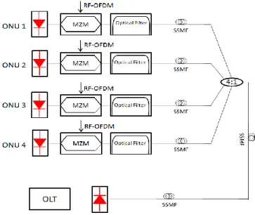
Figure 2-7: P2P OFDM-based system. ... 27
Figure 2-8: OFDM-based PON... 28
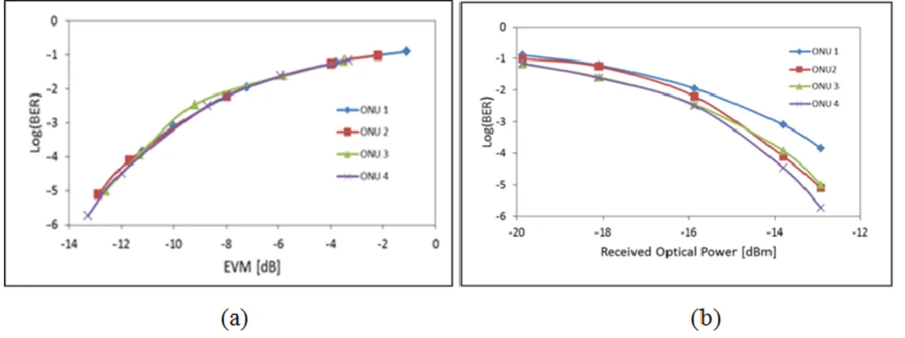
Figure 2-9: (a) BER versus EVM in a back-to-back configuration, (b) BER versus optical power received after 40 km for a 4-ONU system. ... 30
Figure 2-10: (a) BER versus EVM for a 4-user PON, (b) BER versus received
optical power for a 4-user PON. ... 30
Figure 2-11: Schematic diagram of an SOA. ... 32
Figure 2-12: DMT-PON proposed. ... 33
Figure 2-13: Achievable bit rate as a function of SNR (dB) for different value of the gap 𝛤. ... 38
Figure 2-14: Optimal power allocation with water filling solution. ... 40
Figure 2-15: VPI-photonics circuit build for RSOA characterization. ... 42
Figure 2-16: VPI-Photonics RSOA parameter. ... 43
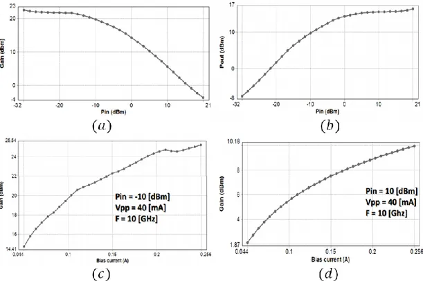
Figure 2-17: VPIPhotonic results. (a) Optical gain versus the input optical power with a fixed bias current of 40mA. (b) Output power versus the input optical power. (c) Optical gain versus the driving bias current for optical input power of -10 dBm. (d) Optical gain versus the bias current for an optical input power of 10 dBm. ... 44
Figure 2-18: Matlab results. (a) Optical gain versus the input optical power. (b) Optical gain versus the bias current. ... 45
Figure 2-19: RSOA frequency response. ... 45
Figure 2-20: VPIPhotonic up-stream simulated setup. ... 47
Figure 2-21: Measured optical spectrum. ... 48
Figure 2-22: (a) Number of bits versus the subcarrier index, (b) estimated SNR versusthe subcarrier index... 48
Figure 2-23: (a) Capacity versus RSOA input power, (b) capacity versus fiber length for input RSOA power of -10dBm... 49
Figure 3-1: Architecture of an AO-OFDM system. ... 59
Figure 3-2: Optical IDFT operation. ... 60
Figure 3-3: Optical IDFT circuit. ... 61
Figure 3-4: AWG configuration for IDFT/DFT operation [7]. ... 63
Figure 3-5: Power spectral distribution of three adjacent subcarriers with N = 8, T = 40 [ps] and FSR = 200 [GHz]. ... 63
Figure 3-7: . Complementary schemes of an AO-OFDM transmitter. ... 65
Figure 3-8: (a) and (b) OFDM symbol. (c) and (d) demultiplexed symbol. (e) and (f) after time gating. (a), (c) and (e) are obtained with the scheme of Figure 3-7(a) and (b), (d) and (f) with the scheme of Figure 3-7(b). (g) BER performance of the two schemes of Figure 3-7. ... 66
Figure 3-9: AO-OFDM setup with AWG modification to insert the CP [19]. ... 67
Figure 3-10: Three subcarriers with CP = 0.1 and R = 12.5 [GHz]. ... 68
Figure 3-11: Eye diagram with and without CP. ... 69
Figure 3-12: AO-OFDM based DPSK modulation setup. ... 70
Figure 3-13: MZM operation for DPSK modulation and signal constellation. ... 70
Figure 3-14: Differential encoder implementation. ... 71
Figure 3-15: Constructive (a) and destructive (b) spectra generation at the outputs of the DLI. ... 72
Figure 3-16: Power spectral distribution of AO-OFDM 16 DPSK modulated subcarriers. ... 72
Figure 3-17: (a) BER as a function of the OSNR for a 12.5 Gb/s DPSK AO-OFDM subcarrier in BtB for different number of subcarriers. (b) Required OSNR as a function of the total CD accumulated for different number of subcarriers. ... 74
Figure 3-18: Required OSNR as a function of the total CD for different number of subcarriers considering 20% of CP. ... 75
Figure 3-19: Setup configuration of an optical DQPSK transmitter and receiver [24]. .. 76
Figure 3-20: (a) BER as a function of the OSNR for a 25 Gb/s DQSK AO-OFDM subcarrier in BtB for different number of subcarriers. (b) Required OSNR as a function of the total CD accumulated for different number of subcarriers. ... 77
Figure 3-21: Required OSNR as a function of the total CD for different number of subcarriers considering 20% of CP. ... 77
Figure 3-22: AO-OFDM system. Mode-locked laser diode (MLLD), pseudo random symbol sequence (PRSS), digital to analog converter (DAC), optical I/Q Mach-Zehnder modulator (I/Q MZM), wavelength selective switch (WSS), array waveguide grading (AWG), single mode fiber (SMF), erbium doped fiber amplifier (EDFA),additive white Gaussian noise (AWGN), local oscillator (LO), balanced photodetector (BPD), analog to digital converter (ADC), frequency domain equalizer (FDE). ... 79
Figure 3-23: Log(BER) versus OSNR [dB/0.1nm]for the theoretical curve (red-line), analytical (blue-line) and simulation (black-line) with different frequency offset
value. ... 83 Figure 3-24: SNR penalty per subcarrier (ΔSNRk) versus the normalized laser
linewidth to symbol duration for AO-OFDM (red line) and CO-OFDM (blue line) at a target BER = 10-3. ... 85 Figure 3-25: SNR penalty per subcarrier (ΔSNREEPN,k) due to EEPN as a function of laser linewidth from analytical eq. (21) and simulation results. The system consists of 37span of 80 km SMF fiber with D=17 ps/(nm-km). ... 86 Figure 3-26: Required OSNR corresponding to a FEC threshold of 10-3 BER as a
function of the averaging window length. (a) PM-QPSK modulation with a linewidth of 300 kHz (red line) and 2 MHz (black line) after 2960 km.(b) PM-16-QAM
modulation with a linewidth of 300 kHz (blue line) and 2 MHz (green line) after 720 km. ... 87 Figure 3-27: Required OSNR as a function of the RX bandwidth in back to back
(BtB) shown in red line, after 37 spans for a sampling rate of 4*Rs (black line) an
6*Rs (blue line). ... 88
Figure 3-28: Required OSNR as a function of FFT-size after 37 spans for a sampling rate equal to 4*Rs (black line) and 6*Rs (blue line). ... 89
Figure 3-29: Maximum number of spans N as a function of the launch power per subcarrier PTx,sub . (a) 21 subcarrier PM-QPSK modulated. Poggiolini estimation
model (blue line), Shieh estimation model (red line), simulated center subcarrier (black dots) and outmost subcarrier (green dots). (b) 7 subcarrier PM-16-QAM modulated. Poggiolini estimation model (blue line), Shieh estimation model (red
line), simulated center subcarrier (black dots) and outmost subcarrier (green dots). ... 92 Figure 3-30: Transmitter setup. Tunable laser diode (TLD), polarization controller (PC), dual-drive Mach-Zehnder (DD-MZM), pulse pattern generator (PPG), erbium-doped fiber amplifier (EDFA), clock (CLK), phase-modulator (PM), single mode fiber (SMF), optical delay line (ODL), optical band pass filter (OBPF), differential quadrature phase shift keying (DQPSK) modulator, variable optical attenuator (VOA), wavelength selective switch (WSS), polarization scrambling (POL), pseudo random bit sequence (PRBS). ... 93 Figure 3-31: Receiver setup. Power meter (PWM), arrayed waveguide grating
(AWG), delay line interferometer (DLI), balanced photodetector (BPD), bit-error rate tester (BERT). ... 94 Figure 3-32: Comb generation setup. ... 95 Figure 3-33: (a) Simulated output pulses from the DD-MZM, (b) and its PSD. ... 97
Figure 3-34: (a) Simulated output pulses from the DD-MZM + PM (red line) and only DD-MZM (blue line), (b) and its PSD after the DD-MZM + PM (blue line) and
before PM (red line). ... 98
Figure 3-35: Pout (red line), first derivative phase (blue line) and second derivative phase (black line). ... 99
Figure 3-36: Variation of broadening factor 𝑇1𝑇0 versus the fiber length 𝑧 (𝑚) in case of a single DD-MZM (blue line) and cascaded DD-MZM + PM (red line). ... 100
Figure 3-37: (a) Experimental measure optical comb spectrum, (b) time domain Gaussian pulse. (c) Numerical simulation of optical comb PSD and (d) ... 101
Figure 3-38: Measured eye diagrams of a 7 ch-transmission (a) B2B (b) after 35-km SMF... 102
Figure 3-39: Spectrum measured at an AWG output port transmitting (a) seven AO-OFDM carriers (b) six subcarriers (the target subcarrier has been switched off) ... 102
Figure 3-40: BER vs received power in BTB for the DQPSK-modulated subcarrier received with direct detection compared with five QPSK subcarriers received by coherent detection (the dashed line corresponds to the mean BER curve of the five subcarriers). A theoretical curve of BER with direct detection is also shown for reference.. ... 103
Figure 3-41: BER vs received power for a DQPSK-modulated subcarrier for B2B, 20-km, 28-km, and 35-km transmission over uncompensated SMF. ... 103
Figure 3-42: Experimental comparison measured transfer function between (a) an AWG and (b) FBG. ... 104
Figure 3-43: (a) BER versus the received optical power for DPSK modulated subcarriers, when a FBG is used at the RX, (b) BER vs. received optical power for DPSK and DQPSK modulation, when an AWG is used at the RX. ... 106
Figure 4-1: Fourier transform of a function in time-frequency plane... 113
Figure 4-2: Wigner distribution of FrFT kernel function. ... 116
Figure 4-3: Tx Schematic of FrFT multicarrier system. ... 119
Figure 4-4: (a) Frequency-to-time conversion, (b) time-to-frequency conversion. ... 120
Figure 4-5: Representation of the signal domain in the normalized time-frequency plane. ... 122
Figure 4-6: Chirp modulation effect on time-frequency plane. ... 123
Figure 4-8: Coherent PM-FrFT setup. ... 126 Figure 4-9: Single subcarrier in time domain before and after SMF transmission. ... 127 Figure 4-10: Subcarrier separation in frequency and time domain before and after
transmission in optical fiber. ... 128 Figure 4-11: Temporal delay between two adjacent subcarrier before and after
transmission on SMF. ... 129 Figure 4-12: (a) Used subcarriers in percent, (b) SMF (Km) as a function of the p-FrFT parameter assuming different subcarrier number with symbol rate 28 Gbaud. ... 130 Figure 4-13: Received pulse repetition ∆𝑡 [ps] as a function of p; theoretical formula in blue line and simulation in black points for a symbol rate transmitted 28 [Gbaud]. .. 131 Figure 4-14: (a) Spectrogram of a single subcarrier 4-QAM modulated with 28
[Gbaud], 𝑁 = 128, and 𝑝 = 0.1 before the SMF fiber, (b) after the SMF... 131 Figure 4-15: Power spectral distribution (PSD) [dB] of a single subcarrier. ... 132 Figure 4-16: Power spectral distribution (PSD) [dB] of 126 subcarriers. ... 132 Figure 4-17: Schematic of FrFT based time lens to achieve frequency-to-time
conversion. 𝑁 is the total number of subcarriers or points of FrFT,... 134 Figure 4-18: (a) BER versus the subcarrier index for R = 28 Gbaud, p =
0.1,OSNR=13.8 dB, 𝑃_𝑎𝑣𝑔 = −1𝑑𝐵𝑚, 𝑁 = 128, and L_SMF = 190 km (b) R = 14
Gbaud, OSNR=11.5 and 𝐿𝑆𝑀𝐹 = 760 𝑘𝑚. Total linewidth ∆𝜗 = 500𝑘𝐻𝑧 ... 135 Figure 4-19: BER as a function of OSNR after 760 km of SMF with R = 28 Gbaud, p = 0.1 and N = 512 for different laser linewidth. In blue line is shown the theoretical curve. ... 136 Figure 4-20: Required OSNR versus linewidth time symbol duration in case of V&V (blue line) and BPS (red line) algorithm are used... 137 Figure 4-21: BER as a function of OSNR after 19span x 80 km = 1520 km fiber
propagation with R = 28 Gbaud, p = 0.1 and N = 1024 for different average power transmission per wavelength (Pavg). In blue line is shown the theoretical curve.. ... 138 Figure 4-22: BER as a function of OSNR ; black line after 380km of SMF; green line after 382km and cyanine line after 385km. ... 139 Figure 4-23: Comparison between digital FrFT (red line) and SRRC (blue line)
single carrier transmission in terms of OSNR penalty, DSP cost, Spectral efficiency and Power consumption considering only CD&PMD. ... 140
1
EVOLUTION OF OPTICAL FIBER COMMUNICATION
1.1 MotivationsGlobal IP traffic will reach 168 Exabyte per month by 2019, with an increase of fivefold over the past five years [1]. Figure 1-1 show the rate of grow per month from 2014 to 2019. This huge grow is due to a large bandwidth request coming from different services like high-definition interactive video, high resolution editing video and distributed system. New terms like big data or deluge of data are used to denote large volume and variety of data overwhelming the physical infrastructure evolution, the capacity to manage and to process it.
Figure 1-1: Cisco Global IP Traffic Forecast, 2014–2019 [1].
Unlike radiofrequency communications that have a very limit bandwidth from 300kHz-300GHz, lightwave technology use the infrared region from 30THz-300THz with capability of supporting Tb/s data over thousands of kilometer. Optical silica fiber is the medium used for such system with a very low cost production, 0.2dB/km loss and small probability of bit-error.
1.2 Evolution of optical transport networks
High speed serial interface (both client and line) and WDM capabilities are required to cope with such amount of data. From 2005 to 2010 the interface rate per-channel has remained nearly constant to 100Gb/s but there is transitions to high order modulation using coherent detection (green line) as shown in Figure 3-43. Using polarization division multiplexing (PDM), advanced coding and of superchannels it is expected to reach Tb/s per line interface. In Figure 3-43 white dots shows commercially available interface like Synchronous Digital Hierarchy/Optical Transport Network (SDH/OTN); black are for routers interface and grey for Ethernet standard. This technology development is due to the up-grade of network operation from circuit-switched serial interface to packet-switched parallel interface.
As shown in Figure 3-43, WDM played a very important role for cost effective data networking able to support very high data rates. Combination with PDM has further increase the data rates to approximately 100Tb/s. A further increase is very challenging because of the electrical bandwidth bottleneck limitation. Non-linear effects are viewed as the fundamental limits for the WDM systems which impose a smaller slope in scaling
Figure 1-2: Evolution of electronically multiplexed serial interface rates and WDM capacities [2]-[3].
the capacities for both research (red triangle) and commercially products (white triangle). Spatial division multiplexing (SDM) and wideband signal is the ultimate physical frontier to overcome 100Tb/s shown with blue rectangular. Integration and use of multi-mode will contribute for a low cost and energy per bit. SDM solution will require, as for WDM system, an up-grade of all networks element, like reconfigurable add/drop multiplexer (ROADM), amplifier and transponders. However the cost of SDM employment seems very high for a mid-term solution.
As another alternative, optical packet/burst switching does not seems to be mature in order to cope with such amount of data [4] even though it has a low cost and energy per bit.
Networks operators are requiring a new generation of optical transport network to efficiently serve the high amount of volume data in a cost effective and scalable manner. Flexible optical network architectures have been proposed in response of this high capacities and disparate traffic granularity needs of the future Internet. Such networks rely on the capability to assign a spectrum portion, data rate and modulation format to bandwidth adaptable connections, with the aim of optimizing the use of the network resources and reducing the ecological impact of the network operation.
In the EU ASTRON project [5], a software-defined transceiver with improved and heterogeneous transmission characteristics based on OFDM that enables the wide and cost-efficient deployment of flexible core networks is proposed. This is achieved by the design and development of cost-optimised, compact and scalable photonic integrated components as well as all the necessary electronic circuits.
The key features of the ASTRON transceiver are the energy‐efficiency and bit‐rate flexibility to support rates from 10Gb/s to beyond 1Tb/s, for use in both access and core networks. To achieve energy efficiency, the ASTRON transceiver does not implement the discrete Fourier transform (DFT) in the electric domain, using power-consuming DSP and ADCs, but uses a specially designed AWG to multiplex and de-multiplex AO-OFDM and Nyquist-WDM signals directly in the optical domain [6].
Flexible optical networks, with the new concept of sliceable bandwidth-variable transponder and flexible optical cross-connect, present the benefit of providing customized spectral grids whenever new lightpaths are established. The allocation of
several channels to form super-channel configurations is performed according to user requests in a highly spectrum-efficient and scalable manner [7]. Modulation formats and center frequency are no more fixed and to establish an optical channel an optical cross connect with variable bandwidth will be able to allocate the desired spectrum requested. According to ITU-T ongoing standardization, the minimum frequency slot unit that can be currently assigned is 12.5GHz and in the future will be scaled down to 6.25GHz [8]. Figure 3-43 show the ITU-T fixed grid comparison with the optical flexi grid. As can be observed from the figure with fixed grid transmission data rate are limit to 100Gb/s because it can be fit inside a frequency fixed slot of 50GHz. The 100Gb/s implementation in long-haul WDM transmission was coupled also with the availability of 100GbE client physical interface standardized by IEEE 802.3 in 2010. Next step for higher bit rate in WDM transmission is the use of 400Gb/s which interfaces is far from industrial availability. 400GbE task force has been launched by IEEE 802.3 in March 2014 for a standard approval expected by 2017.
If we consider the 400Gb/s implementation in a fixed 50GHz grid it will probably overlap with other frequency slot. If higher order modulation is considered the required
OSNR is very high due to laser phase noise and tight filtering in cascaded ROADM. So the need for flexi grid in case of 400Gb/s data rates is crucial [9].
1.3 Evolution of optical access networks
Legacy access networks consist of pairs of copper point-to-point (P2P) links between the local exchange and customers; these systems can support digital subscriber line (DSL)-based services and Internet Protocol Television (IPTV), but are inadequate for future broadband multimedia applications. Hence, the last mile has become a critical bottleneck, limiting the profitability of network operators, who are experiencing a substantial reduction in revenues, due in part to the telecom competition, and in part to an increasing use of mobile phones.
Fiber-based systems are an effective solution for next the generation access networks (NGAN), as they can provide a large bandwidth to residential and business users [10]. PON architecture is the most deployed fiber to the x (FTTx) system, where x depends on where the optical link terminates [11]. The point-to-multipoint (P2MP) topology uses a passive optical splitter in the remote node (RN) to connect 32, 64 or even 128 users to the optical line termination (OLT) in the central office (CO). Users share the optical media with a time-division multiplexing (TDM) approach, and the downstream signal is broadcasted to all the optical network units (ONU), that select only the data corresponding to their own destination addresses. In the up-stream link, each ONU transmits only at time-slots assigned by the OLT, using a time division multiple access (TDMA) protocol to avoid collisions. Statistical multiplexing and media access control layer allow dynamic bandwidth assignment (DBA), to efficiently exploit the optical resources.
To further expand the bandwidth capacity, current FTTx systems should evolve toward WDM-based PONs, where the passive splitter in the RN is replaced by a arrayed waveguide grating (AWG)-based multiplexer. In this case, each ONU is assigned one or two wavelengths, and it is equipped with a tunable laser or a reflective semiconductor optical amplifier, which re-modulates an optical carrier sent from the OLT. In 2012, the full service access network (FSAN) consortium has selected the time and wavelength division multiplexing (TWDM)-based PON approach as a solution to upgrade optical access systems, with a smooth upgrade for deployed networks [12].
In a way similar to the WDM approach, an OFDM-based system uses orthogonal narrow-bandwidth subcarriers to transmit/receive to/from different ONUs [13]. The system flexibility and bandwidth granularity is higher, compared to the WDM technology, because the OLT can manage the number of the subcarriers assigned to each ONU and no guard-band is required. In addition, adaptable modulation format and power scheme are possible, and the near-far problem of TDM/TDMA systems is overcame, because there is no synchronization requirement for the ONUs, that are placed at different distances from the CO. This becomes of critical importance, when the users are assigned to different operators that do not share the same equipment in the CO. In addition, OFDM-based systems have colorless (non-user specific) ONUs, without expensive tunable lasers or large band amplifiers. Using a cyclic-prefix (CP), it is possible to perform circular convolution, to equalize chromatic dispersion in the frequency domain, with a reduced digital signal processing (DSP) complexity. In addition, OFDM systems can be integrated with both TDM and WDM technologies, to further increase the flexibility and the capacity of optical access systems. An OFDM configuration allows unbundling of the local loop (ULL), so that different operators can share the same infrastructure. The implementation of ULL in the NGAN is a strategic requirement for the European Union policy on competition an liberalization in the telecommunications market. Open access is extremely beneficial for NGANs, since it is associated with an increased competition, that drives higher levels of broadband penetration at lower prices.
1.4 High-speed single carrier and multicarrier transmission
In a single carrier transmission, only one wavelength carry the data information. An ideal pulse shaping, sinc(t) pulse in time domain, is usually used to avoid intersymbol-interference (ISI) and to occupy the smallest possible bandwidth satisfying the Nyquist principle. In frequency domain it has approximately a rectangular spectrum, rect(f). In a multicarrier trasmission the information is carried by multiple low-rate subcarriers which are overlapped in order to maximize the spectral efficiency, in one wavelength. OFDM is one of the approach used by multicarrier trasmission with overlapped subcarriers.
1.4.1 Single carrier trasmission
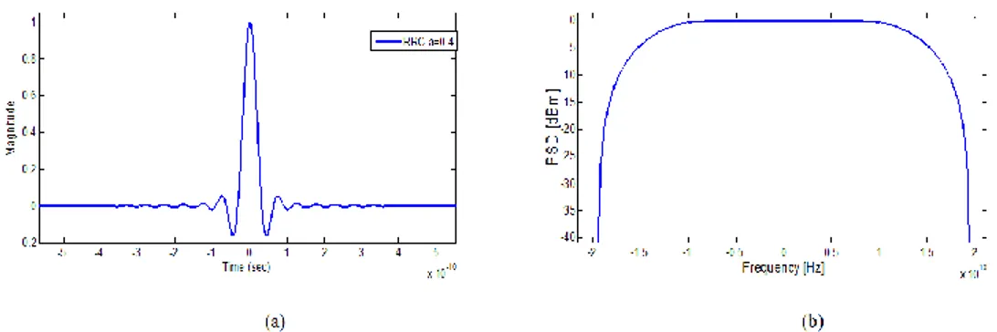
Sinc-shaped time domain waveforms do not have a match filter to maximize the signal-to noise ratio (SNR) at the receiver. To maximize the SNR a squared root raised cosine filter (RRC) is used both in the transmitter and receiver. The RRC pulses which cover 64 symbols with a roll-off factor of a = 0.4 as a compromise between system complexity and system performance is shown in Figure 1-4 (a) & (b) in time and spectrum domain respectively.
Figure 1-4: Time (a) and frequency (b) behaviour of a RRC pulse with roll-off factor
a=0.4.
Design of a single carrier transceiver is shown Figure 1-5 based on a 100Gb/s OIF implementation agreements for integrated polarization multiplexed quadrature modulated
Figure 1-5: (a) A polarization multiplexed quadrature modulated integrated
transmitter and intradyne coherent receivers. The optical power from a CW laser is divided in two parts and each part is independently modulated by a quadrature modulator, as shown in Figure 1-5(a).
The quadrature modulators typically comprise two nested Mach-Zehnder modulators with bias control and a 90º phase shifter in the outer modulators with phase control [14]-[15]. The output modulated signal are then combined in two orthogonal polarization states to obtain the signal transmitted on the optical fiber.
The coherent receiver required eight photodiode, four set of balanced detectors and linear amplifier, two ninety degree hybrid and two polarization splitting one for the received signal and the other for the local oscillator as shown Figure 3-43(b).
Single-carrier transceiver implementations are the preferred solutions for short-haul and metro applications, with baud rates ranging between 42.7 and 64 GBaud and high-level modulation formats, with 50 to 75 GHz channel spacing, achieving spectral efficiencies above 5.3 bit/s/Hz [9].
Compare to multi-carrier solutions, a single carrier uses adaptive algorithm for channel estimation, like constant modulus algorithm (CMA) and his variant for higher order modulation, like radius direct equalizer (RDE). Design of optical modulators is complex for higher order modulation which will increase the system cost.
In general it is easy to implement and require low cost, lower size and a low power dissipation. Compare to multicarrier it provide lower spectral efficiency but has the benefit of easy bandwidth allocation and network management.
ADC requirements regarding bandwidth and number of bits resolution for multi-level modulation is very challenging. At OFC 2016, NTT announced industry-first 16nm ultra-low power DSP for both 100G QPSK long-haul and 200G 16QAM metro optical links [16].
1.4.2 Multicarrier transmission
Targeting high speed channel generation, of the order of Tb/s, has meet with challenging limitation due primarily to limit sampling rate of ADC/DAC. To overcome this limitation, one of the approached proposed is to split the transmitted bandwidth in smaller sub-channels (subcarriers) in parallel which has led to creation of superchannels. The sub-channels are no needed to be overlapped as in OFDM. Nyquist optical/electrical
Figure 1-6: Different multicarrier transmission setup [17]
filters can be used to achieve same spectral efficiency as OFDM, known as Nyquist-WDM (NNyquist-WDM). Figure 1-6 show some of the most investigated multiplexing technique for creating superchannels [17] using more than one wavelength. Strictly speaking dense-WDM (Ddense-WDM) is a multicarrier transmission. The main difference is the spacing between the subcarriers. At the transmitter side an optical comb generation is usually used to ensure that no cross-talk happen in frequency domain between the subcarriers. Multicarrier trasmission based on coherent WDM (CoWDM) use rectangular time domain pulse and was proposed first in [18] with a spectral efficiency achieved of 1 b/s/Hz and 3 dB of penalty. In [17], as shown in Figure 1-6, an off-set QAM is proposed with a T/2 delay on one of the modulator arms. Off-set QAM shows less penalty because ISI and cross-talk is properly eliminated by using practical component. The main drawback of this setup is the phase control stabilization on each subcarrier because otherwise the cross-talk is very high. If offset-QAM is not used it require a high over-sampling rate. For a realistic implementation it requires a photonic integration, which is mandatory in all multicarrier systems.
Multicarrier trasmission based on no-guard-interval optical OFDM (NGI-OFDM) has been proposed and experimentally investigated in [19]-[20]. Similar to Co-WDM,
NGI-OFDM uses rectangular time domain pulse shape but with no phase control or offset-QAM modulation. To obtain good results an oversampling rate of a factor of 4 is used together with electrical pre-filter to eliminate aliasing effect. Electrical pre-filter are used for subcarrier separation at the receiver side. For both, CoWDM and NGI-OFDM the subcarrier spacing is equal to the data rate of each modulated subcarrier.
Multicarrier trasmission based on Nyquist-WDM (NWDM) is proposed in [21] to improve the receiver sensitivity and to relax the requirements of the received filters by using an extra optical filter at the transmitter with a rectangular spectrum profile. Non ideal rectangular profile filter is very difficult to realize consequently residual cross-talk exits between the channels. Guard interval can relax the spectrum profile but in that case the system will achieve same spectral efficiency as in DWDM. Otherwise, electrical FIR filters can be used as in [22] with many number of taps at the transmitter side to keep cross-talk level low.
Multicarrier trasmission based on coherent OFDM is another option to create superchannels with IFFT/FFT processing in the electrical domain. The highest capacity obtained using digital IFFT is 101.7Tb/s presented in [23]. The main drawback is the high peak to average power ratio (PAPR) which require non-linear mitigation. Phase noise mitigation technique are complex requiring a radio-frequency pilot tone which lie at the centres of the OFDM band to track the phase noise [24]. Cyclic prefix introduce overhead and reduce the spectral efficiency.
For next generation 400G transmission systems multi-carrier modulation formats will most likely to be used. Figure 1-7 show several 400G transceiver implementations for short-haul (SH), metro, long-haul (LH) and ultra-long-haul (ULH) applications according to OIF-Tech-Options-400G-01.0 [9]. The 400G application is sub-divided into short-haul (SH), Metropolitan (Metro), Long-Haul (LH) and Ultra Long-Haul (ULH). SH applications target very high spectral efficiency. Metro applications target at least 1000 km with the presence of ROADMs with fixed grid (100 GHz) or newly designed flexgrids (75 GHz). For LH application, the presence of ROADMs is optional but with distances close to 2000 km. ULH applications should be compatible with distances beyond 2000 km. Moving to 400G solutions faces a trade-off between spectral efficiency
and reach flexibility. If higher modulation levels are employed, reduced transmission reach is
Figure 1-7: Potential 400G architectures in the state of the art. 1DAC and ADC characteristics taken either from Section 6 or from the state of the art. 2Distances reported either in the state of the art or from OIF contributions. 3OIF2014.030.00, 4OIF2015.030.01, 5OIF2015.100.00, 6OIF2015.037.01, 7OIF2014.031.00 [9].
unavoidable because these high-order QAMs require higher OSNR, and are more sensitive to laser phase noise and to fibre non-linear effects. The higher the QAM order, the lower the tolerance to narrow optical filtering due to ROADM cascading.
According to the IEEE 802.3bs 400GbE Task Force timeline adopted in September 2015, the standard is expected in December 2017 [25].
1.5 Thesis outline and contributions
From the analysis done in the previous section both access and transport networks are bottleneck when considering the future demand of bandwidth, low cost solution and low power consumption.
The research objective of this thesis is to employ optical communications technology to provide a high speed novel transmission data to overcome the traditional time division multiplexing technique used commonly in access and transport layer.
In this thesis the goal is to provide a design and analysis of cost effective fiber optic access network for unbundling the local loop employing analytical and simulations tools. Propose, design and analyze high speed all optical OFDM trasmission. Establish an experimental test-bed to experimentally verify the analyzed high speed real time trasmission.
Propose, design and analyze a novel multicarrier trasmission for optical communications systems and identify the limitations of the proposed trasmission.
The following present a pre chapter overview of the thesis and the main contributions. In chapter 1, motivation and state of the art of current research topic are described for both access and transport layers.
In chapter 2 OFDM is proposed for optical access network with direct detection for a low cost solution. OFDM offers colorless ONUs, reduced DSP complexity and compatibility with TDM/WDM technology. It also allows unbundling the local loops if reflective semiconductor optical amplifier (RSOA) are used at the ONU side. RSOA characterization is performed analytically and by simulation commercial software. Adaptive OFDM is used to overcome the RSOA bandwidth limitations and evaluation of the access networks based on RSOA and OFDM is performed for system design parameters.
In chapter 3 all optical OFDM (AO-OFDM) is proposed with a very high spectral efficiency and aggregated data rate. Direct detection DPSK/DQPSK AO-OFDM trasmission is investigated with and without cyclic prefix. Polarization multiplexing AO-OFDM with coherent detection is evaluated by analytically formula and simulations result. Experimentally AO-OFDM system is demonstrated at National Institute of Communications and Information Technology (NICT), Japan, with no optical gating and chromatic dispersion for both direct and coherent detection by using a wavelength selective switch (WSS) at the transmitter side and an AWG at the receiver. Optical comb generation for AO-OFDM is evaluated both analytically and by experimental result.
Finally, an experimental comparison is performed between a fiber Bragg grating (FBG) and AWG for AO-OFDM demupltiplexing.
In chapter 4 a multicarrier trasmission based on electrical fractional Fourier transform (FrFT) is theoretically investigated and proposed for high speed optical communications networks. Theoretical time lens effect is derived based on FrFT and chromatic dispersion effect supported by simulation results. A fundamental study to explore the limits of the proposed system is performed and detailed results have been presented. It is demonstrated that the proposed optical transmission can encode data on both polarization and no dispersion compensation is needed at the receiver side. Further more, it is shown that the effect of phase noise is relaxed if compare to electrical OFDM transmission.
1.5.1 List of publications
The work presented in this thesis has led to the following publications:
J. Hoxha, J. Morosi, S. Shimizu, P. Martelli, P. Boffi, N. Wada, and G. Cincotti, “Spectrally-efficient all-optical OFDM by WSS and AWG,” Optics Express 23(9), 10986-10996 (2015)
J. Morosi, J. Hoxha, P. Martelli, P. Parolari, G. Cincotti, S. Shimizu, N. Wada, and P. Boffi, "25 Gbit/s per User Coherent All-Optical OFDM for Tbit/s-Capable
PONs," J. Opt. Commun. Netw. 8, 190-195 (2016)
P. Zakynthinos, G. Cincotti, M. Nazarathy, R. Kaiser, P. Bayvel, R. I. Killey, M. Angelou, S. B. Ezra, M. Irion, A. Tolmachev, B. Gomez Saavedra, J. Hoxha, V. Grundlehner, N. Psaila, G. Vollrath, R. Magri, G. Papastergiou and I. Tomkos, “
Advanced Hybrid Integrated Transceivers to Realize Flexible Terabit Networking, “ IEEE Photonics Society News, February 2014, Vol. 28, No. 1
J. Hoxha, G. Cincotti, S. Shimizu and N. Wada, "FBG- and AWG-based
AO-OFDM demultiplexing," Photonics in Switching (PS), 2015 International
Conference, Florence, 2015, pp. 82-84.
J. Hoxha, G. Zarra and G. Cincotti, "A flexible OFDM system for unbundling the
local loop in optical access networks," Networks and Optical Communications -
J. Hoxha, G. Cincotti, M. Nazarathy, P. Zakynthinos and I. Tomkos,
"Software defined transceivers for high-speed flexible optical
networks," Future Network and Mobile Summit (FutureNetworkSummit),
2013, Lisboa, 2013, pp. 1-8.
J. Hoxha and G. Cincotti, "Performance limits of all-optical OFDM
systems," 2013 15th International Conference on Transparent Optical Networks
(ICTON), Cartagena, 2013, pp. 1-4.
J. Hoxha, G. Cincotti, N. P. Diamantopoulos, P. Zakynthinos and I.
Tomkos, "All-optical implementation of OFDM/NWDM Tx/Rx," 2013
15th International Conference on Transparent Optical Networks
(ICTON), Cartagena, 2013, pp. 1-4.
J. Morosi, J. Hoxha, S. Shimizu, P. Martelli, P. Boffi, N. Wada, G. Cincotti, “
QPSK- based all optical OFDM with direct and coherent detection.” 2015
Fotonica AEIT Italian Conference on Photonics Technologies - Turin, Italy, May 6 - 8 2015
J. Hoxha, G. Zarra, G. Cincotti, “OFDM-based solutions for unbundling the local
loop in optical access networks,” 16o Convegno Nazionale sulle Tecniche
Fotoniche nelle Telecomunicazioni (FOTONICA), Naples, Italy 2014
J. Hoxha, G. Cincotti, “System performance of coherent all-optical OFDM in
long-haul transmission,”15o Convegno Nazionale sulle Tecniche Fotoniche nelle
References
[1] http://www.cisco.com/c/en/us/solutions/collateral/service-provider/visual-networking-index-vni/VNI_Hyperconnectivity_WP.html
[2] P. J. Winzer, “Challenges and Evolution of Optical Transport Networks‘”, ECOC 2010, Torino, Italy, Paper We.8.D.1.
[3] http://optical-networks.iscte-iul.pt/presentations/alcatel.pdf
[4] R. S. Tucker. Optical packet switching: A reality check. Optical Switching and Networking, 5(1):2–9, June 2008.
[5] http://www.ict-astron.eu/
[6] J. Hoxha, G. Cincotti, M. Nazarathy, P. Zakynthinos, I. Tomkos, “Software defined transceivers for high-speed flexible optical networks,” Future Network & MobileSummit 2013, Lisbon, Portugal 2013.
[7] A. Napoli, et al., “Next Generation Elastic Optical Networks: the Vision of the European Research Project IDEALIST,” IEEE Communications Magazine, Vol. 53, No. 2, February 2015.
[8] ITU-T. Transmission systems and media, digital systems and networks, February 2012
[9] http://www.oiforum.com/wp-content/uploads/OIF-Tech-Options-400G-01.0.pdf [10] Shumate,”Fiber-to-the-Home: 1977-2007,” J. Lightw. Technol., vol. 26, no. 9, pp.
1093-1103, May 2008.
[11] T. Koonen,”Fiber to the Home/Fiber to the Premises: What, Where, and When?,” vol. 94, no. 5, pp. 911-934, May, 2006.
[12] J. J. Zhang and N. Ansari,” Design of WDM PON with tunable lasers: The upstream scenario,” J. Lightw. Technol., vol. 28, no. 2, pp. 228-236, January 2010.
[13] N. Cvijetic,“OFDM for next-generation optical access networks,” J. Lightw. Technol. vol.. 30, .pp. 384-398, 2012.
[14] http://www.oiforum.com/public/documents/OIF-PMQ-TX-01.1.pdf [15] http://www.oiforum.com/public/documents/OIF_DPC_RX-01.1.pdf
[16] http://www.ntt-electronics.com/en/news/2016/3/industry-first-16nm-100g-200g-coherent-dsp.html
[17] J. Zhao and A. D. Ellis, “Offset-QAM based coherent WDM for spectral efficiency enhancement”, 19, 14617-14631 (2011)
[18] A. D. Ellis and F. C. G. Gunning, “Spectral density enhancement using coherent WDM,” IEEE Photon. Technol. Lett. 17(2), 504–506 (2005).
[19] R. Dischler and F. Buchali, “Transmission of 1.2 Tb/s continuous waveband PDM-OFDM-FDM signal with spectral efficiency of 3.3 but/s/Hz over 400 km of SSMF,” OFC’09, post-deadline paper PDP2.
[20] S. Chandrasekhar, X. Liu, B. Zhu, and D. W. Peckham, “Transmission of a 1.2-Tb/s 24-carrier no-guard-interval coherent OFDM superchannel over 7200-km of ultra-large-area fiber,” ECOC’09, post-deadline paper PD2.6.
[21] G. Bosco, A. Carena, V. Curri, P. Poggiolini, and F. Forghieri, “Performance limits of Nyquist-WDM and CoOFDM in high-speed PM-QPSK systems,” IEEE Photon. Technol. Lett. 22(15), 1129–1131 (2010).
[22] R. Schmogrow, R. Bouziane, M. Meyer, P. A. Milder, P. C. Schindler, R. I. Killey, P. Bayvel, C. Koos, W. Freude, and J. Leuthold, "Real-time OFDM or Nyquist pulse generation – which performs better with limited resources?," Opt. Express 20, B543-B551 (2012).
[23] D. Qian, M. Huang, E. Ip, Y. Huang, Y. Shao, J. Hu, and T. Wang, "101.7-Tb/s (370×294-Gb/s) PDM-128QAM-OFDM Transmission over 3×55-km SSMF using Pilot-based Phase Noise Mitigation," in Optical Fiber Communication Conference/National Fiber Optic Engineers Conference 2011, OSA Technical Digest (CD) (Optical Society of America, 2011), paper PDPB5.
[24] S. L. Jansen, I. Morita, T. C. W. Schenk, N. Takeda and H. Tanaka, "Coherent Optical 25.8-Gb/s OFDM Transmission Over 4160-km SSMF," in Journal of Lightwave Technology, vol. 26, no. 1, pp. 6-15, Jan.1, 2008.
17
OPTICAL ACCESS NETWORKS BASED ON ELECTRICAL OFDM
2.1 IntroductionOptical access networks comprise the link between ONU (customers) and OLT (service provider) as shown in Figure 2-1. This is usually called ‘last mile’ from the service provider prospective. The OLT is then connected to the core network, which provides very high speed transmission from Gb/s up to Tb/s using either SONET/SDH technology. This high speed transmission is not available at the ONU because of installed copper infrastructure which cannot provide this high amount of data. The solution on the so called ‘last-mile bottleneck’ is using the optical fiber.
In the PON architecture a single fiber originates from the OLT and power splitter are usually used to deliver the signal to ONU.
Different multiple access techniques are used to avoid collisions in the up-stream traffic originated from the ONUs, which include TDMA, WDMA, optical code-division multiplexing access (OCDMA).
OFDMA is an alternative solution which provides a continues transmission (not a burst one), enable dynamic bandwidth allocation which provide a high flexibility in both time and frequency domain and make use of DSP for channel equalization.
In order to increase the data rate and the number of ONU subscriber, WDM is one the solution to be used together with OFDMA.
2.1.1 Electrical OFDM with optical modulation
Optical field of a continues wave (CW) laser offers at least five degree of freedom for information modulation: field amplitude, intensity, phase, frequency and polarization. In practice frequency modulation is not used.
In general, the optical OFDM solution can be divided into two main groups: 1)Coherent detection (CO) with field modulation 2)Direct detection with intensity/field modulation IM/DD shown in Figure 2-2(a) and (b), respectively. CO-OFDM present a better receiver sensitivity and a higher spectral efficiency if compare to DD-OFDM [3].
Figure 2-2: (a) Block diagram of IM/DD and (b) CO-OFDM using optical modulation [2].
2.1.1.1 IM/DD
The OFDM multicarrier signal is generated in the electrical domain, as shown in Figure 2-2(a), where an analog front end is used for radio frequency (RF) up converter after the DAC. An optical modulator (OM) is used to convert the RF-OFDM signal in the optical
domain using either the field or intensity modulation. In case of field modulation an I/Q modulator is needed. In case of intensity modulator a real electrical OFDM signal is needed to modulate the optical carriers. A DC bias is used to generate a positive electrical signal. Because at the receiver side a single photodiode is used, the optical carrier should be transmitted. Half of the power is used for the optical carrier and only half for the OFDM signal. This system was proposed for the first time in [4] and shown in Figure 2-3.
Figure 2-3: Optical OFDM with DC bias and DD receiver [4].
At the receiver, some nulls power are produced at particular frequency obtained from the mixing terms between sidebands and optical carriers after optical fiber propagation. This is due to chromatic dispersion which can cause conversion from amplitude modulation into phase modulation [5]. To avoid this effects, an optical filter is used to filter the double side band OFDM signal as in [6]. The optical signal at the output of the filter is called single side band (SSB) OFDM signal. In alternative an optical single side band (OSSB) can be generated if a Hilbert transform is used as in [7] without the need of an optical filter. In this case a dual electrode MZM is driven by a real OFDM signal and by its Hilbert transform. The real OFDM signal is obtained by the Hermitian symmetry and the Hilbert transform is obtained by using 90° electrical hybrid. In this case there is no need for RF up-conversion because the spacing from the optical carrier can be obtained by using virtual subcarriers. In alternative, only a Hermitian symmetry can be used together with an optical filter to obtain a SSB OFDM signal. The optical modulator is a dual electrode Mach Zehnder modulator (MZM) biased in quadrature. The Hermitian
symmetry is simply obtain by using one half of the IFFT size as the complex conjugate of the other half. Even in this case some of the subcarriers are filled with zero (virtual subcarriers) to leave a guard band between the OFDM signal and the optical carrier. A 180° electrical phase shift is used between the two arms of the MZM.
2.1.1.2 CO detection
In the CO-OFDM approach optical carrier is not transmitted because it is suppressed and the optical OFDM signal show more power allocated in it. An optical I/Q modulator is usually used which generate only one sideband. For this reason no optical filter is needed as in IM/DD setup. At the receiver side a complete access to the full optical field by using a local oscillator allow to maximize the transmitted data rate and no guard band is needed [3]. The sensitivity of the receiver is increased because of the local oscillator and long reach trasmission is possible to achieve. As shown in Figure 2-2 (b) at the receiver side an optical 2x4 90° hybrid is needed together with balanced photodiode and CW local oscillator. The analog front end RF is shown as in reference [2], but of course this is not mandatory and will simplify the CO-OFDM setup.
There are also many drawbacks in CO-OFDM like: phase noise and frequency shift originated by CW local oscillator. Advanced algorithm are required for mitigating this effects in DSP.
Due to the high cost derived from the optical hybrid, CW local oscillator and DSP transceiver usually the CO-OFDM is not considered for the moment as a solution for the PON.
2.2 OFDM
The schematic of OFDM setup is shown Figure 2-4. The transmitted binary data streams are mapped to complex symbols from a particular modulation formats (M-PSK, M-QAM or differential modulation) [1]. Then a serial to parallel (S/P) block is used to convert the symbols in parallel. Modulated symbols enter the inverse fast Fourier transform (IFFT) which provide an efficient method for computing the IDFT[9]. The output of the IFFT can be written as [10]:
𝑥[𝑛] = ∑ 𝑋[𝑘]𝑒𝑗2𝜋𝑘𝑛𝑁 𝑁−1
𝑘=0
2-1
with 𝑋[𝑘] input modulated complex symbols (Fourier coefficients), 𝑥[𝑛] provide the output time series where the n-th time domain sample is the sum of N complex exponential functions and N is the IFFT size. In order to avoid overlapped between OFDM symbols, guard intervals is added (cyclic prefix).
Figure 2-4: Schematic of OFDM setup.
In this case a copy of the data 𝑥𝐶𝑃= (𝑥[𝑁 − 1], … 𝑥[𝑁 − 𝑁𝐶𝑃]) will be added at the beginning of the sequence 𝑥[𝑛] which define the length of the OFDM symbol. The duration of the cyclic prefix, 𝑇𝐶𝑃, is related to the channel impulse response length. To avoid inter-symbol interference it should be made longer which on the other hand decrease the spectral efficiency of the system. The complex output is then sampled at a rate double of Nyquist frequency equal to 2 ∙ 𝑁 2𝑇⁄ , where 𝑇 is the OFDM symbol period without cyclic prefix. To relax the bandwidth limitation due to low pass filtering and the
sampling rate some of the subcarriers, usually 20%, are filled with zeros. This subcarriers are usually called virtual subcarriers. After the IFFT a complex signal is obtained and in order to transmitted both the in-phase and quadrature component a frequency up-conversion is performed at 𝜔𝑐.
The analog complex OFDM signal transmitted, considering only one OFDM symbol is written as:
𝑠(𝑡) = 𝑒𝑗𝜔𝑐𝑡∑ 𝑋[𝑘]𝑒𝑗𝜔𝑘𝑡 𝑁−1
𝑘=0
∗ ℎ𝑇𝑥 2-2
where ℎ𝑇𝑥 is the transmitter filter impulse response.
Figure 2-5: Power spectral density of the OFDM signal.
If the transmitted symbols are uncorrelated the power spectral density of the OFDM signal is [1]: 𝑃𝑠(𝜔) = 𝑇 𝑁2∑ 𝐸[|𝑋[𝑘]|2] 𝑁−1 𝑘=0 𝑠𝑖𝑛𝑐2(𝜔 − 𝜔 𝑘) 2-3
where 𝐸[|𝑋[𝑘]|2] is the average power per symbol on kth subcarrier.
The power spectral density is shown in Figure 2-5. The total bandwidth of the OFDM signal is approximated as: 𝐵𝑊𝑇 ≈ 𝜔𝑘𝑁 + 2𝜋 𝑇⁄ if a null-to-null bandwidth definition is used.
To recover the transmitted symbols a Fourier transform is performed on the received signals after down-conversion. The channel/filtering effects is neglected. The received signal is then written as:
𝑌[𝑘] =1 𝑇∫ 𝑠(𝑡)𝑒 −𝑗𝜔𝑘𝑡𝑑𝑡 𝑇 0 = ∑ 𝑋[𝑖] 𝑁−1 𝑖=0 1 𝑇∫ 𝑒 𝑗(𝜔𝑖−𝜔𝑘)𝑡𝑑𝑡 𝑇 0 = ∑ 𝑋[𝑖] 𝑁−1 𝑖=0 𝑒𝑗(𝜔𝑖−𝜔2 𝑘)𝑇 𝑠𝑖𝑛 [(𝜔𝑖− 𝜔2 𝑘)𝑇] (𝜔𝑖− 𝜔𝑘)𝑇 2 = 𝑋[𝑘] 2-4 where the last equivalence is obtained if 𝜔𝑖 = 𝜔𝑘 (orthogonality of OFDM subcarriers). Another condition can be derived from Eq. 2-4: 𝜔𝑖− 𝜔𝑘 = 2𝜋𝑚 𝑇⁄ which states that in order to avoid inter-carrier interference the transmitted subcarriers must be spaced an integer multiply 𝑚 of the inverse OFDM symbol duration. In order to be orthogonal and to recover the transmitted symbol with a match filter. The orthogonality condition allow to transmit overlapped spectra and to increase the spectral efficiency.
The received signal considering channel and filtering effect is sampled with an analog to digital converter after filtering with a low pass filter to avoid aliasing. The cyclic prefix is then removed and the discrete FFT operation is performed. The discrete symbols can be written as: 𝑌[𝑘] = ∑ 𝑦[𝑛] 𝑁−1 𝑛=0 𝑒−𝑗2𝜋𝑘𝑛𝑁 2-5 where: 𝑦[𝑛] = ∑ 𝑋[𝑖] 𝑁−1 𝑖=0 𝑒−𝑗2𝜋𝑛𝑁𝑖 ∗ ℎ𝑇𝑥[𝑛] ∗ ℎ[𝑛] ∗ ℎ𝑅𝑥[𝑛] 2-6 ℎ𝑇𝑥[𝑛], ℎ[𝑛], ℎ𝑅𝑥[𝑛] are the sampled version of the low pass filter, channel impulse response and received filter, respectively. Eq. 2-4 perform a circular convolution due to the cyclic prefix because the extended OFDM symbol now appear like a ‘periodic signal’ when the convolution with the channel impulse response is performed. Due to the FFT
property the received symbols can be written as: 𝑌[𝑘] = 𝑋[𝑘] ∙ 𝐻[𝑘] where 𝐻[𝑘] is the discrete overall channel transfer function. A zero forcing equalizer can be designed by estimating the channel transfer function, 𝐻̂[𝑘], by dividing the received symbols obtaining an equalized signal as:
𝑌̂[𝑘] = 𝑌[𝑘]/𝐻̂[𝑘] 2-5
2.3 Electrical OFDM for PONs
Next generation optical access networks is expected to deliver high data rate providing multiple service using low-cost architectures and a flexible bandwidth allocation. Current TDMA-PON present high complexity to scale the data rate up to Gb/s due to the burst mode trasmission implementation. On the other hand, WDMA-PON can provide a high data rate by using a dedicated wavelength for each ONU. However it lacks in flexibility bandwidth allocation and bandwidth granularity.
OFDMA-PON was first proposed in [13] to provide multiple service. The main principle of OFDMA is to use a subset of different subcarriers for each ONU. If only 4 ONU is consider for simplicity like in [1], the down-stream and up-stream schematic is then shown in Figure 2-6, where each ONU process only a group of the total OFDM subcarriers and the OLT process all the subcarriers.
OFDMA is also compatible with WDMA-TDMA and they can all be used together. If the OLT assign a group of subcarriers to a ONU but the it has not enough traffic data to delivery then it can share the non-used subcarriers with other ONU using TDM. OLT is able to process in the same time slot different ONU and different wavelength (WDM) [2]. Albeit many advantage like high spectral efficiency, reduced cost compare to WDM (because OFDM needs less receivers) and transparent service provider there are also challenges for up-stream scenario like: different length of optical fiber connecting each ONU to OLT, carrier offset between the different subgroup of subcarriers and different polarization state. For down-stream the OFDM-PON scenario is more realistic and able to work on real time transmission.
2.3.1 Unbundling the local loop
In this work the focusing will be on the up-stream scenario. Another important requirements of the next generation optical access networks is to allow competition among different service provider. This should be provided through the ‘unbundling of the local loop’ (ULL) technology. Nowadays this is accomplished by traditional legacy twisted pair DSL (digital subscriber line) access with the two most popular alternative Asymmetric DSL (ADSL) and ADSL+. In the near future, the Very High-Speed DSL (VDSL) with vectoring technology is expected to provide high data rate per user up to 100Mb/s or more, an increase on the number of customer and a fast return on the investment (ROI) by reusing the same infrastructure [14]. Vectoring technology is basically based on a reduce crosstalk between DSLs.
The most used ULL technologies are direct access and bit-stream [15]-[16]. In direct access different operators who require to access the ONU is provided with a point-to-point physical access even though the infrastructure is provided by the proprietary service provider (incumbent). Usually at the CO each operators have its own ‘room’ with its own modem and their own DSL Access Multiplexer (DSLAM). So basically, the competitive operator is leasing the copper from a wholesale or service provider.
On the other hand, bit-stream technology is based on a virtual unbundling at data link layer (or Ethernet). In other words the incumbent is wholesaling virtual point-to-point connections to ULL. Virtual Unbundling of the Local Access (VULA) at the CO based
![Figure 1-2: Evolution of electronically multiplexed serial interface rates and WDM capacities [2]-[3]](https://thumb-eu.123doks.com/thumbv2/123dokorg/2834455.4668/21.918.202.787.656.971/figure-evolution-electronically-multiplexed-serial-interface-rates-capacities.webp)
![Figure 1-3: Spectrum utilization for fixed and flexi grid [7].](https://thumb-eu.123doks.com/thumbv2/123dokorg/2834455.4668/23.918.230.751.623.989/figure-spectrum-utilization-for-fixed-and-flexi-grid.webp)
![Figure 2-1: Schematic of the access networks [1].](https://thumb-eu.123doks.com/thumbv2/123dokorg/2834455.4668/36.918.243.743.778.983/figure-schematic-access-networks.webp)
![Figure 2-3: Optical OFDM with DC bias and DD receiver [4].](https://thumb-eu.123doks.com/thumbv2/123dokorg/2834455.4668/38.918.183.809.359.562/figure-optical-ofdm-dc-bias-dd-receiver.webp)
![Figure 2-6: Down-stream and up-stream scenario for PON based on OFDM [1].](https://thumb-eu.123doks.com/thumbv2/123dokorg/2834455.4668/43.918.175.798.768.965/figure-stream-stream-scenario-pon-based-ofdm.webp)