UNIVERSITY
OF TRENTO
DEPARTMENT OF INFORMATION AND COMMUNICATION TECHNOLOGY
38050 Povo – Trento (Italy), Via Sommarive 14
http://www.dit.unitn.it
MANAGEMENT OF DISTRIBUTED MEASUREMENT SYSTEMS
BASED ON ABSTRACT CLIENT-SERVER PARADIGMS
Fernando Pianegiani, David Macii, Paolo Carbone
April 2004
Management of Distributed Measurement Systems
Based on Abstract Client-Server Paradigms
F. Pianegiani, D. Macii, P. Carbone
DIEI – Dipartimento di Ingegneria Elettronica e dell’Informazione Università degli studi di Perugia, via G. Duranti 93 – 06125 Perugia, Italy
Phone: +39 075–5853629, Fax: +39 075–5853654, Email: [email protected], [email protected]
Abstract – This paper describes in detail a Java-based, client-server architecture specifically conceived to allow a flexible con-trol of remote devices. The main attributes of the proposed solu-tion are portability and flexibility. The former feature is assured by the employment of the TCP/IP protocol suite and by the Java lan-guage properties. The latter is due to the high level of abstraction of the system implementation, that addresses multi-user issues and a wide range of possible applications with a high code reusability. In particular, the proposed architecture can be easily upgraded so as to fit different kinds of devices, by simply adding a limited amount of code on the server-side of the overall system.
Keywords – Internet, Java, distributed measurement system, cli-ent-server architecture, remote calibration.
I. INTRODUCTION
In recent years, the growing demand for improved inter-operability between electronic instruments, the increase in PC computing and input/output capabilities along with the diffu-sion of standard buses specifications (e.g. IEEE 488, IEEE 1394, PCI/PXI and VME/VXI) and network protocols, have favoured the development of software tools oriented to the implementation of distributed control architectures. Such tools represent enabling technologies for the development of home automation networks [1], human-robot interactive ap-plications [2]-[5], real-time collaborative telemedicine sys-tems [6] and, more generally, distributed measurement sys-tems (DMS) both for educational and industrial purposes [7]-[9]. Unfortunately, many of the commercially available soft-ware tools devoted to Virtual Instrument (VI) implementation (e.g. Labview, Lab Windows and HPVEE) often require spe-cific applications to be installed on client computers [10]. Moreover, since they are based on proprietary technologies, remote control applications can not be freely distributed or easily extended. Conversely, common object remote brokers and interfaces have been defined to create extensible and dis-tributed programming environments. By using Corba tech-nology, for instance, each application is the result of a col-laboration between several objects distributed over commu-nicating networks and coded using various languages. Thus, new programs can easily and quickly be extended to address dedicated purposes. A similar goal can also be reached with object oriented languages, like Java and C++, without modi-fying the original structure of the source code [11]. This re-sult is achieved by using abstract classes and by loading d y-namically software libraries such as dynamic link libraries (dll) on Windows platforms or shared object (so) libraries under Unix.
Even if many solutions have been proposed on this topic, a certain lack of detailed low-level descriptions of possible implementations has been observed in literature. So one of the aim of this paper is to give a full description of a highly abstract Java-based client-server architecture that is able to control measurement systems remotely. Unlike other robust, highly distributed multi-server architectures [8][10][12], the solution presented in this paper focuses mainly on the opti-mization of the communication systems between multiple clients and a single server, whose high flexibility and ease of reconfiguration has been considered very important for the development of future multi-layered distributed applications.
In following sections, at first the overall operating envi-ronment is described and the design choices are explained. Then, it is shown that the integration of new instrumentation and PC-cards, such as CAN or IEEE 488 controllers, can be accomplished without modifying the code of the client-server architecture. Finally, an example of system implementation devoted to remote calibration purposes is presented.
II. DESCRIPTION OF THE DISTRIBUTED MEASUREMENT SYSTEM
Because of the rapid evolution of information exchange standards, any newly devised architecture for remotely controlling instrumentation should include enough features to accommodate actual hardware and software specifications, possibly anticipating future technological developments. This is one of the reasons why the proposed system has been designed to be highly abstract, easily extensib le and user-friendly.
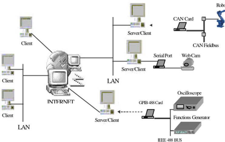
The system architecture is shown in Fig. 1. It consists of a group of distributed client-server applications that can be upgraded to control general-purpose instrumentation over the Internet. These instruments are either plugged directly into PCs (e.g. PCI data acquisition boards) or interfaced via a bus controller (e.g., IEEE 488 and IEEE 1394 cards). Security issues related to client-server communications have been addressed by using the Secure Socket Layer (SSL) protocol for each connection established between client and server ports. Obviously, the server is protected by a password. The access and the possible sharing of the available resources are managed using the multithreading approach. When a user requests the execution of any control operation, the server application runs a new dedicated thread. Since more than one thread can be run and processed independently, the system
CAN Card Robot CAN Fieldbus Client Client Client Server/Client Server/Client LAN GPIB 488 Card Functions Generator Oscilloscope Amp0.1Freq 4..56 IEEE 488 BUS Serial Port Web Cam
Server/Client
LAN
INTERNET
Fig. 1. Extensible distributed measurement system.
allows the execution of multiple operations at the same time. A portion of the server application has been conceived to engage, release and share the requested resources and to manage simultaneous accesses. The client-side application is started automatically when a user connects to the server homepage using a Java-enabled browser. Users are presented with a graphical user interface (GUI) showing the list of controllable interface cards and instruments, directly installed on the server. Moreover, if a standard bus controller (e.g. IEEE 488-PCI bus interfaces) is chosen, an additional search is performed to find devices connected to the bus. A list of all resources is shown on a graphical panel, enabling selection of a specific device. Then, by using secure socket connections and the TCP/IP communication protocol, information can be exchanged with the server unit (instrument control commands, parameters and reports). Finally, obtained measurement data can be saved locally or visualized on the screen. Notice that, the use of full Java-based graphical panels has been preferred over servlet technology, because it reduces the loading time of GUI, thus improving system performance.
Unlike other valuable Java-based multithreading solutions that need the insertion of several Java server classes to manage any instrument newly connected to the server [13], the most important feature of the proposed architecture is its easy extensibility. In fact it is possible to manage new cards and instruments installed on a server unit without recompiling or modifying any code component. It is only necessary to add a limited portion of upgrading code on the server. This operation is feasible either locally or remotely. In the following subsections the chosen programming tools will be described, along with a functional and temporal analysis of the proposed architecture.
A. Software Tools
As mentioned in the introduction, several languages are used to implement distributed control systems. The architecture described in this paper has been coded using the Java and C
languages. Java simplifies the development of data exchange mechanisms between client and server systems, by offering graphical user interfaces and client-server communication methods based on socket connections and applet executions. Moreover, the Java Secure Socket Extension (JSSE) set of packages implements a Java version of SSL (Secure Sockets Layer) and TLS (Transport Layer Security) protocols and in-cludes functionality for data encryption, server authentic a-tion, message integrity, and optional client authentication.
On the other hand, C is the language most frequently used to realize drivers and libraries for the low-level control of devices at the highest execution speed. In order to translate programming elements from Java to C, the Java Native Inter-face (JNI) and native methods have been employed [14]. However, native methods demand knowledge of both Java and C languages. Better results and lower development ef-forts could have been achieved using Microsoft Visual Java [13]. However this product was recently withdrawn from market. To describe the system at the architectural level, the unified modeling language (UML) has been employed. This language is useful to describe organizational and technical systems. To this purpose it employs 12 types of diagrams d i-vided into 3 main categories: diagrams to model static appli-cation structures, diagrams to represent different aspects of dynamic behaviors and diagrams to organize and manage the application modules [15].
B. Functional Description of the Client-Server Architecture
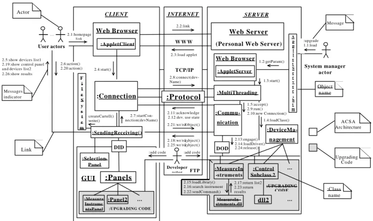
The architecture is composed of a client, a server and an Internet units. The implementation code is divided in 2 parts: an Abstract Client-Server Architecture (ACSA) that repre-sents the permanent part of the code and an upgrading code portion inserted for expansion purposes. The working princi-ple of the overall architecture is based on 3 main functions responsible for client-server communications, abstract man-agement of the available physical resources and upgrading operations. In order to describe the functional and time rela-tions between objects and classes of the ACSA architecture and the upgrading code, a UML collaboration diagram has been employed, that is shown in Fig. 2. In this diagram users, developers and managers are represented as 3 actors that al-low data exchange between client and server for remote automation purposes. The sequence of operations is as fo l-lows. The system manager actor or the server operating sys-tem starts the server application asynchronously by opening the AppletServer.htm file. This file contains the number of the server port accepting connections and a list of the avail-able resources. This data is essential to access and to share over the Internet the devices connected to the server. Then,
Appletserver.htm loads an applet that reads the information
stored in the html file through the getParameter() method. Finally, the applet starts the MultiThreading class that allows the server to enter a waiting state, expecting connection re-quests.
2.8:connect(dev- Name)
2.11:acknowledge 2.12:dev. use state 2.21:wr/rdObject() 2.18:wr/rdObject() 2.25:wr/rdObject() 2.4:start() CLIENT SERVER Web Server (Personal Web Server)
W W W 1.3:start() INTERNET TCP/IP A p p l l e t S e r v e r . h t m 2.2:link 2.3:load applet 2.17:return list2 2.23:return results … :UPGRADING C O D E FTP System manager actor Developer actor Web Browser :AppletServer 1.2:getParam() 1.4:loadClass() :Protocol 2.5:show devices list1
2.19:show control panel a n d devices list2 2.26:show results 2.6:action() 2.20:action() :createCartell() :write() F i l e S y s t e m 1.5:accept() 2.9:run( ) 2.10:new Connection() :MultiThreading :add co d e :upgrade 1.1:load ... dll2 2.13:engage() 2.14:loadDriver() 2.24:release() :DeviceMa-nagement 2.1:homepage link :add code :Commu-nication :Control Subclass 2 2.15:loadLibrary() 2.16:search instrument 2.22:sendCommand() MeasureIn -struments.dll … 2.7:startCon- nection(devName) User actors :MeasureIn -struments Link Messages indicator :Class name Message A C S A Arc hitecture Upgrading Code Actor Object name DID DOD :SendingReceiving() :Selection-Panel … :UPGRADING CODE :Measure Instrume ntsPanel :Panel2 GUI :Panels Web Browser :AppletClient :Connection
Fig. 2. UML collaboration diagram of the client-server architecture.
The user actors load the client application by opening the server homepage and executing the AppletClient applet. They can establish a link with the server by means of the
Connec-tion class which generates a socket connecConnec-tion to Multi-Threading. The connection or the disconnection to or from
the server, can be carried out by the user actors through a dedicated menu in several graphical panels. They are used to choose the instruments, to insert control commands and pa-rameters, and to visualize the responses from the server.
If MultiThreading accepts the connection request, it starts the Communication class in a dedicated thread and waits for a new request. In this way, more than one user actor can have access simultaneously to the server system and control one of the available instruments. In order to allow data exchange between client and server connection sockets, object in-put/output streams are defined. Initially, such streams are used by the server to send acknowledge messages concerning the connection state; then, they are used by the client to ceive the list of the available resources. The selection of re-sources is performed in 2 stages: at first, user actors have to choose one of the devices or controllers in the received list shown through SelectionPanel. Then, if a controller for a par-ticular input/output standard bus is chosen (e.g., IEEE 488, IEEE 1394), a search for devices physically connected to the bus is started automatically. This mechanism is carried out by a native method implemented in the driver of the bus control-ler. After completing the first selection stage, Connection
sends to the Communication class the name of the chosen de-vice and waits for answers about its availability. The rules allowing the dialog between Connection and Comunication are defined in the Protocol class. If the requested resource is available, the corresponding panel, subclass of Panels, will be shown to the User actors. Thus, they can select one of the instruments found in the second search stage, and can insert measurement data and control commands in the panel fields. The user requests are sent to the server through the
Sendin-gReceiving class. This operation employs an input
serializ-able object of the DeviceInputData (DID) class whose attrib-utes are suitable to represent all kinds of device input data. Finally, Communication and the subclasses of
DeviceMan-agement, transfer to the instruments the requests received
from the client and return measurement results, if available. This occurs through an output serializable object of the
De-viceOutputData (DOD) class.
For each new resource installed on the server, the
devel-oper actor has to upgrade the system by adding new
management code (highlighted in grey in Fig. 2). In particular, a new subclass of DeviceManagement has to be implemented, as well as one or more dll drivers for the low-level control of the device and a new dedicated GUI panel. Moreover, when the new card or instrument is connected to the server, the manager actor has to upgrade the parameters list in the AppletServer.htm file.
III. ABSTRACT MANAGEMENTOF THE AVAILABLE RESOURCES
The easy extensibility of the system depends on the ab-straction features of the ACSA. This has been achieved on the basis of 3 design choices:
• the declaration of device-independent attributes in the DID and DOD classes;
• the dynamic loading, on the client-side, of the control panels inheriting attributes from the Panels super-class;
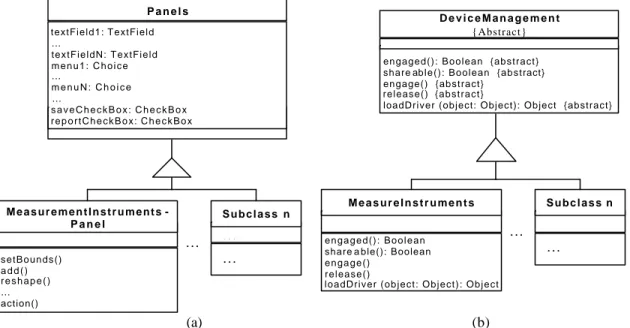
the dynamic loading, on the server-side, of the device spe-cific subclasses inheriting methods from DeviceManagement. The two former features in the list allow to exchange management and measurement data through a common inter-face, regardless of the kind of controlled devices. This means that, even if a different virtual front panel is employed for each instrument, control messages, either written in text fields or set by clicking on checkboxes, are encapsulated in a unique data record before being transferred. A dual mecha-nism is used to return measurement results to the client. All of the fields of these records are declared inside the Panels superclass as shown in Fig. 3(a), in which a UML class dia-gram describes the hierarchic relationship between Panels and its device-dependent subclasses.
As regards the third feature in the list, DeviceManagement allows the management of any controllable resource. This is accomplished by declaring abstract methods such as
share-able(), engaged(), engage(), release() and loadDriver(object: Object). As shown by the UML class diagram plotted in fig.
3(b), all of these methods are implemented in the
Device-Management subclasses whose structure depends on the
dif-ferent characteristics of devices connected to the server. The device-dependent methods, unknown to the ACSA, are called
by the Communication class through an instance variable of
DeviceManagement.
Methods shareable() and engaged() are devoted to detect the device availability following a specific user request. Instead,
engage() and release() allow to employ such device if it is
available and to release it when the user stops controlling the resource. Finally, loadDriver(object) loads dynamically the dll or so drivers, containing the C native methods necessary to control the requested instrument.
IV. AN EXPERIMENT OF REMOTE CALIBRATION
An application of the ACSA architecture has been devel-oped to carry out remotely calibration procedures [16] on some measurement instruments located in the laboratories at University of Perugia. In particular, an IEEE 488 card has been installed on the server-side of the system to allow the remote calibration of a Hewlett Packard 3440A multimeter and a Hewlett Packard 54603B oscilloscope by means of a Fluke 5500A multifunction calibrator. For this purpose, the upgrading code of the client-server architecture needed the implementation of three main software units: a subclass of the DeviceManagement class, a C programme and a subclass of the Panels class. In the first unit the loadDriver method call two native methods, implemented in the second unit, that allow to look for all measurement instruments connected to the IEEE 488 card and to carry out the calibration proce-dures. The method that execute this last operation must ceive in input some calibration data specified from the re-mote user of the system on the client-side. This data consist of the name of the instrument chosen to be calibrate (Device Under Calibration (DUC)), the kind of the measurements that
engaged(): Boolean {abstract} share able(): Boolean {abstract} engage() {abstract}
release() {abstract}
loadDriver (object: Object): Object {abstract}
D e v i c e M a n a g e m e n t
{Abstract}
M e a s u r e I n s t r u m e n t s
e n g a g e d ( ) : B o o l e a n share a ble(): Boolean e n g a g e ( )
r e l e a s e ( )
loadDriver (object: Object): Object
… … S u b c l a s s n … M e a s u r e m e n t I n s t r u m e n t s -P a n e l s e t B o u n d s ( ) a d d ( ) r e s h a p e ( ) … action() … … S u b c l a s s n … P a n e l s textField1: TextField … textFieldN: TextField m e n u 1 : C h o i c e … m e n u N : C h o i c e … s a v e C h e c k B o x : C h e c k B o x r e p o r t C h e c k B o x : C h e c k B o x (a) (b)
the DUC has to carry out (e.g., volt AC/DC, current AC/DC, resistance 2/4 wire, frequency), the range of values of the measurements, the number of points per range and the num-ber of measurements that have to be carried out for each point. Then, the same native method analyze the results of the measurements, correct in real-time the possible found devia-tion by some commands of the calibrator and return the cali-bration report. This contain date, outputs of the calibrator, minimum and maximum measurement values permitted from the reading and range uncertainty of the DUC, measurements executed by the DUC, deviations of the measurements from the outputs of the calibrator and the calibration timing.
The routine that manage the calibration operations has been realized in C, rather than for example in LabView, to increase the performance of calibration operations and to al-low a quick upgrade of the calibration system when new measurement instruments need to be calibrate.
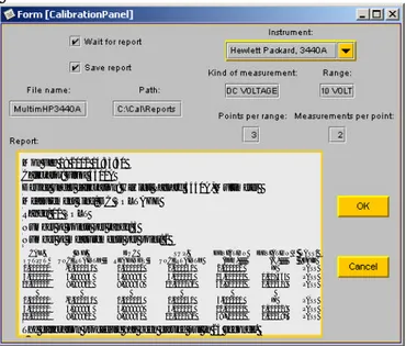
Using the Forte for Java tool, the third unit of the upgrad-ing code has been implemented to create a graphical user in-terface for the client-side. In particular, the virtual panel shown in Fig. 4 contain the report of a calibration procedure executed on the Hewlett Packard 3440A multimeter.
Mon Feb 18 2002 14:33:40 Calibrator: Fluke 5500A
Device under calibration: Hewlett Packard 3440A, Multimeter Measurement kind: DC VOLTAGE
Range: 10 VOLT Number of points per range: 3 Number of measurements per point: 2
CAL. OUTPUT INF. UNCERTAINTY DUC READINGS SUP. UNCERTAINTY DEVIATION (ppm) DEVIATION (%) PASS/ FAIL 0,000000 -0,000040 0,000002 0,000040 2,000000 X PASS 5,000000 4,999885 4,999985 5,000115 15,000000 0,007564 PASS 10,000000 9,999810 9,999938 10,000190 61,900000 0,000619 PASS 0,000000 -0,000040 0,000003 0,000040 3,000000 X PASS 5,000000 4,999885 4,999989 5,000115 11,000000 0,000228 PASS 10,000000 9,999810 9,999941 10,000190 58,700000 0,000587 PASS The calibration procedure has been carried out in 24 seconds.
Fig. 4. Client-side panel for the remote management of cali-bration operations.
C
ONCLUSIONSIn this paper, an abstract client-server architecture has been described that controls instrumentation over the Inter-net. This architecture exploits the flexibility, the portability and the network-oriented features of the Java language, thus avoiding the use of proprietary software tools. Moreover, it has been conceived to allow an easy upgrade of the system when new hardware resources are connected to the server computer. This results from the high level of abstraction characterizing both client- and server-side applications. In fact, while the low-level control of devices is performed by
routines written in C, the use of abstract classes and the dy-namic loading of native methods allow the client to commu-nicate with every instrument, regardless of its specific properties. This approach to the remote management of instrumentation is further improved by the multithreading mechanism, allowing more than one user to take simultaneous measurements independently.
Exploiting the extensibility features of the system, a dedi-cated application based on the ACSA architecture has been developed to carry out calibration procedures remotely. In particular, an experimentation of this application has been dedicated to the calibration of some measurement instru-ments located in the laboratories at University of Perugia and connected to the server of the system by an IEEE 488 bus controller.
R
EFERENCES[1] T. Saito, I. Tomoda, Y. Takabatake, K. Teramoto, K. Fujimoto,
“Gateway technologies for home network and their implementations,” in Workshop Distributed Computing Systems (DCS), pp. 175-180, 2001.
[2] D. Buhler, W. Kuchlin, G. Grubler, G. Nusser, “ The Virtual Automation Lab-Web based teaching of automation engineering concepts,” in Proc. Engineering of Computer-Based Systems (ECBS), pp. 156- 164, 2000.
[3] A. Speck, H. Klaeren, “ RoboSiM: Java 3D robot visualization,” in
Proc. International Conference on Industrial Electronics, Control and Instrumentation (IECON) , Vol. 2, pp. 821-826, 1999.
[4] A. S. Sekmen, Z. Bingul, V. Hombal, S. Zein -Sabatto, “ Human-robot interaction over the Internet,” in Proc. IEEE Southeastcon, pp. 223-228, 2000.
[5] P. G. Backes, K. S. Tso, J. S. Norris, G. K. Tharp, J. T. Slostad, R.G. Bonitz, K. S. Ali “ Internet -based operations for the Mars Polar Lander mission,” in Proc. International Conference on Robotics and
Automa-tion (ICRA), Vol. 2, pp. 2025-2032, 2000.
[6] Mee Young Sung, Moon Suck Kim, Myung-Whun Sung, Eom Joon Kim, Jae Hong Yoo, “ CoMed: a real-time collaborative medicine sys-tem,” in Proc. Computer Based Medical Systems (CBMS), pp. 215-220, 2000.
[7] Wang Lihui, B. Wong, Shen Weiming, Sherman Lang, “ A Web-based collaborative workspace using Java 3D,” in Design Computer
Sup-ported Cooperative Work (CSCW), pp. 77-82, 2001.
[8] L. Benetazzo, M. Bertocco, F. Ferraris, A. Ferrero, C. Offelli, M. Par-vis, V. Piuri, “ A Web-based distributed virtual educational labora-tory,” IEEE Trans. Instrum. and Meas., Vol. 49, no. 2, pp. 349-356, Apr. 2000
[9] K. Michal., W. Wieslaw, “ A new Java-based software environment for distributed measurement systems designing,” in Proc. Instr. and Meas.
Tech. Conf. (IMTC) , Vol. 1, pp. 397-402, 2001.
[10] P. Arpaia, A. Baccigalupi, F. Cennamo, P. Daponte, “ A measurement laboratory on geographic network for remote test experiments,” IEEE
Trans. Instrum. and Meas., Vol. 49, no. 5, pp. 992-997, Oct. 2000.
[11] D. Buhler, G. Nusser, W. Kuchlin, G. Gruhler, “ The Java Fieldbus Control Framework-object oriented control of fieldbus devices,” in Proc. Object-Oriented Real-Time Distributed Computing (ISORC), pp.
153-160, 2001.
[12] M. Bertocco, M. Parvis, “Platform Independent Architecture for Distributed Measurement Systems,” in Proc. Instr. and Meas. Tech.
Conf. (IMTC) , Vol. 1, pp. 648-651, 2000.
[13] D. Grimaldi, L. Nigro, F. Pupo, “ Java-based distributed measurement systems,” IEEE Trans. Instrum. and Meas. , Vol. 47, no. 1, pp. 100-103, Feb. 1998.
[14] Sun Microsystems, web address: http://java.sun.com .
[15] Object Management Group, web address: http://www.omg.org/uml. [16] A. Carullo., M. Parvis, A. Vallan “ A travelling standard for the
cali-bration of data-acquisition boards” in Proc. Instrumentation and