1
SCUOLA DI SCIENZE
Dipartimento di Chimica Industriale “Toso Montanari”
Corso di Laurea Magistrale in
Chimica Industriale
Classe LM-71 - Scienze e Tecnologie della Chimica Industriale
I
NVERSE AND REGULAR PHENYL
-
AZOLE LIGANDS FOR
LUMINESCENT
I
RIDIUM
(III)
COMPLEXES
Tesi di laurea sperimentale
Presentata da:
Riccardo Mancini
RELATORE
Prof. Letizia Sambri
CORRELATORE
Dr. Elia Matteucci Sessione II ___________________________________________________________________________________________________________ Anno Accademico 2014-2015 ___________________________________________________________________________________________________________2
I
NDEX1 Abstract ... 3
2 Introduction ... 4
2.1 Why just LEDs? ... 4
2.2 How OLEDs work? ... 7
2.3 The Importance of Iridium(III) Complexes ... 10
3 Purpose of the work ... 14
4 Results and Discussion ... 16
4.1 The Starting point: N2 – C4 ... 16
4.2 Step 1: Ligands synthesis ... 18
4.2.1 Synthesis of 2 ... 18
4.2.2 Synthesis of 3 ... 19
4.2.3 Synthesis of 6 ... 19
4.2.4 Synthesis of 7 ... 20
4.3 Step 2: Synthesis of the complexes ... 21
4.3.1 Synthesis of C3 ... 24 4.3.2 Synthesis of C2 ... 25 4.3.3 Attempted Synthesis of N4... 27 4.3.4 Attempted Synthesis of N3... 28 4.3.5 Synthesis of N3F ... 30 5 Conclusion ... 33 6 Experimental Section ... 34
6.1 Materials and methods ... 34
6.2 Synthesis ... 35
3
1 A
BSTRACTIn the modern society, light is mostly powered by electricity which lead to a significant increase of the global energy consumption. In order to reduce it, different kinds of electric lamps have been developed over the years; it is now accepted that phosphorescence-based OLEDs offer many advantages over existing light technologies. Iridium complexes are considered excellent candidates for bright materials by virtue of the possibility to easily tune the wavelength of the emitted radiation, by appropriate modifications of the nature of the ligands. It’s important to note that the synthesis of Ir(III) blue-emitting complexes is a very challenging goal, because of wide HOMO-LUMO gaps needed for produce a deep blue emission.
During my thesis I planned the synthesis of two different series of new Ir(III) heteroleptic complexes, the C and the N series, using cyclometalating ligands containing an increasing number of nitrogens in inverse and regular position.
I successfully performed in the synthesis of the required four ligands, i.e. 1-methyl-4-phenyl-1H-imidazole (2), 4-phenyl-1-methyl-1,2,3-triazole (3), 1-phenyl-1H-1,2,3-triazole (6) and 1-phenyl-1H-tetrazole (7), that differ in the number of nitrogens present in the heterocyclic ring and in the position of the phenyl ring. Therefore the cyclometalation of the obtained ligands to get the corresponding Ir(III)-complexes was attempted.
I succeeded in the synthesis of two Ir(III)-complexes of the C series, and I carried out various attempts to set up the appropriate reaction conditions to get the remaining desired derivatives.
The work is still in progress, and once all the desired complexes will be synthesized and characterized, a correlation between their structure and their emitting properties could be formulated analysing and comparing the photophysical data of the real compounds.
4
2 I
NTRODUCTIONBefore electric lighting became common in the early 20th century, street and home illumination was provide by gas light, oil lamps, or just fires. Now lights are mostly powered by electricity. Over the years the energy problems have led to an impressive increase of the research of luminescent materials,1 which may be used in more fields of knowledge for example as pH sensors,2,3 photocatalysts,4,5 photoxidant,6 in medical imaging as biological labelling reagents,7 or especially in many kind of LED devices. Nowadays any supermarket shows different kind of bulbs, with different prices and different performance. There are four main categories of electric lights: incandescent lamps (Figure 1-A), halogen (Figure 1-B), compact fluorescent (CFL, Figure 1-C) and light-emitting diode (LED, Figure 1-D).
Figure 1 – Common type of bulbs
The first type of lamp, introduced in 1879 by Thomas A. Edison patent, was commercialized in the 1920s. It works with an incandescent bulb’s tungsten filament that is heated until it glows: these lamps have the worst performance quality because less than 3% of the input energy is converted into usable light, while about 97% is converted into heat rather than visible light, and this rapidly lead to increasing in the temperature bulbs, reaching high values.8
Halogen lamps were marketed in 1960s with an advanced filament system. These lamps work exactly like incandescent ones, but are able to set up a reversible chemical reaction cycle with the evaporated tungsten, making them more long-lived. A gas, typically
5 halogens, was included in the bulbs and reacts with the tungsten in order to form a halide. Subsequently the mixture, coming into contact with the hot filament decomposes and re-deposited on the filament, creating a cycle. In this way the lifetime of a halogen lamp may be at least double of a normal incandescent light bulb, although the filament is much hotter. The big disadvantages of these lamps is the low efficiency and the problem to reduce unintentional ultraviolet (UV) exposure, in fact these kind of lamps usually have a UV-absorbing glass filter around the bulb causing an increasing in price. The third type, compact fluorescent lamps (CFL), marketed in 1938, use a low pressure mercury-vapour gas-discharge lamp that exploit fluorescence to produce visible light. The mercury vapour is excited with an electric current and produce UV light, which causes a phosphor coating luminescence. The efficiency of this type of lamp is higher than the incandescent one, but considering that they contain mercury, CFL are classified as hazardous waste and for this reason they are not reliable with the environmental problems of the modern society. Finally, in 1962, the earliest red LED appeared (Figure 2).
Figure 2 - Historical trend of the most common lights sources
It was developed by Nick Holonyak Jr. at General Electric Company.9 A light-emitting diode (LED) is a basic pn-junction diode, which emits light when activated. When a fitting voltage is applied, electrons are able to recombine with electron holes within the device, releasing energy in the form of photons. This effect is called electroluminescence, and the color of the light (corresponding to the energy of the photon) is determined by the energy band gap of the semiconductor.Recent developments in LEDs permit them to be used in environmental and task lighting. In order to build good luminescent devices, reasonable
6 efficiency, high stability, easy and economical fabrication methods are needed. It is now accepted in the electroluminescent industry that phosphorescence-based LEDs offer many advantages over existing lighting technologies:
Extremely long life and no maintenance;
Emit light oriented point, without loss radial light;
The LEDs are tunable, hence obtaining lights of different color; They have high efficiency, can be greater than 100 lm/W;
LEDs are small and allow you to create compact lamps, moreover they are shock and vibration resistant. This is a particular advantage in industrial and street lighting application;
LEDs light haven’t IR and UV radiation, moreover they are mercury free and for these reasons they are safety.
In contrast with these undoubted advantages, LEDs also show some disadvantages, such as:
LEDs are currently more expensive than other kind of lamps, due to materials; moreover, the low productivity makes this product more expensive;
Their performance largely depends on the operating temperature; high temperatures may result in overheating the LED package. For this reason they need an adequate heat sink;
LEDs light is not approximate as a spherical light distribution as the classic bulbs, but rather a lambertian ones. So LEDs are difficult to apply, without using different lenses, to uses needed a spherical light field;7 In the 1980s, C. W. Tang and S. A. VanSlyke at Eastman Kodak Company developed the first double layer OLED device.10 The principal difference between OLEDs and LEDs is that LEDs are made of inorganic semiconductors only, while in OLEDs are present also some organic layers. This variation allows OLEDs to be particularly flexible and transparent, and make them unique. Figure 3 shows the structure of the OLED.
Figure 3 – First type of double layer OLED device
Starting from the bottom, there was glass as substrate and an indium-tin-oxide (ITO) anode. On the top of it, the first organic layer (about 750 Å), the aromatic diamine in Figure 4A, work as hole transporting layer. The second organic layer was the emitting film, about 600 Å thick, and the luminescent molecule was the 8-hydroxyquinoline aluminium (Alq3,
in Figure 4B). Above all, the Mg:Ag cathode (10:1) tooks place. All the layers were deposited by vacuum deposition (about 10-5 torr). Moreover since OLEDs are water-sensitive, the build process must take place in a clean room, an environment with a low level of pollutants, water and particles.
Figure 4 – First organic layer (A), and second organic layer (B)
8 This was the first example of how “organic materials can indeed be viable alternatives for optoelectronic application such as displays”.10 Since then, research in OLEDs grew
considerably. Over the next years, research on multilayers OLEDs have led to the development of even more efficient devices, with the features of flexibility, low power consumption, lightweight and, generally, with great characteristic for displays. The structure remains the same, nevertheless other levels are added in order to improve their performance. In Figure 5 is reported an example of structure.
Figure 5 – An example of a multilayer OLED
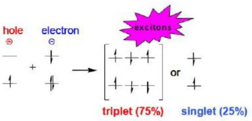
The total thickness of the organic layers is about 1000 Å, which consist of a hole transporting layer (HTL), an emissive layer containing host material and sometimes a dopant (EML), on it an electron transporting layer (ETL) takes place. When the voltage is applied, the positive and negative charges are injected into the organic materials. Hole and electrons, both migrate through the emissive layer and here they recombine to form excitons. Approximatively 75% of excitons created in OLEDs are triplets (spin parallel) and only 25% are singlets (spin antiparallel), this means that statistically the excitons are product in ratio 3:1, triplets and singlets (Figure 6).
9
Figure 6 – Triplet and singlet excitons state
To harness the most of the formed excitons, OLEDs utilize phosphorescent materials, then the exciton decay radiatively, and the color of this emission depends on the exciton’s energy state.
In contrast, a fluorescent device (like CFL lamps) only utilizes singlet excitons, then the remaining 75% is lost as non-radiative decay processes, for example heating of the device.11 This inefficient utilization of triplet excitons limits the internal quantum efficiency of fluorescence-based devices to only 25%. For this reason, quantum efficiency is significantly improved in OLEDs which turn out to be potentially more efficient than all other lighting devices mentioned above.
10 The research about phosphorescent emitters focus the attention especially on transition metal complexes, which are remarkable triplet emitters. The triplet excited state in these compounds is populated as consequence of the ISC process, which is favoured by the spin-orbit coupling due to presence of a heavy atom. In Figure 7 a typical Jablonski Diagram is reported, illustrating the fluorescent and phosphorescent emission. The states of a molecule are settled vertically by energies and grouped horizontally by spin multiplicity. Straight arrows indicate radiative transition (F and P), squiggly arrows indicate non radiative processes (IC, ISC).
Figure 7 – Jablonski diagram
Cyclometalated Ir(III) complexes exhibit an high photoluminescence quantum yield (PLQY), and they are considered excellent candidates for forming bright materials by virtue of the possibility to easily tune the wavelength of the emitted radiation.
In fact, the emission color can be readily tuned from blue to red by appropriate modification of the nature of the cyclometalating ligands and/or the ancillary ligands, as demonstrated by M. E. Thompson at the beginning of century.12 It is possible to obtain stable and efficient emitters in the ranges of the three primary colors. In Figure 8 are shown some different structures and the CIE color coordinates of Ir-based organometallic heteroleptic complexes.13
11
Figure 8 – Different structures of Ir-based heteroleptic complexes
It is interesting to note that currently red-green Iridium(III) emitting complexes have been well described, whereas blue emitting complexes are still less common. This is because wide HOMO-LUMO gaps are difficult to obtain and, moreover, the high energy levels of blue-emitters heavily marks the device durability.14 Many strategies have been pursued to stabilize the HOMO and/or destabilize the LUMO, and causing a hypsochromic shift, such as:
1. Reduction of the ring size of the aromatic N-heterocycle, switching from the typical pyridine to a smaller structure with an higher reduction potential in order to raise the LUMO of the complexes; 15
2. Increase the number of nitrogen atoms in the azole ring;16 3. Addition of electron-withdrawing groups, typically fluorine; 12
4. Variation of ancillary ligand. In fact, by changing or chemically modifying the ancillary ligand is possible to destabilize the LUMO, while keeping the HOMO relatively unperturbed.14
Several studies investigating on each of the strategies pronounced above are reported in the literature, and it appears clear that the efficiency in the blue-shifting of each approach widely differs from the others.
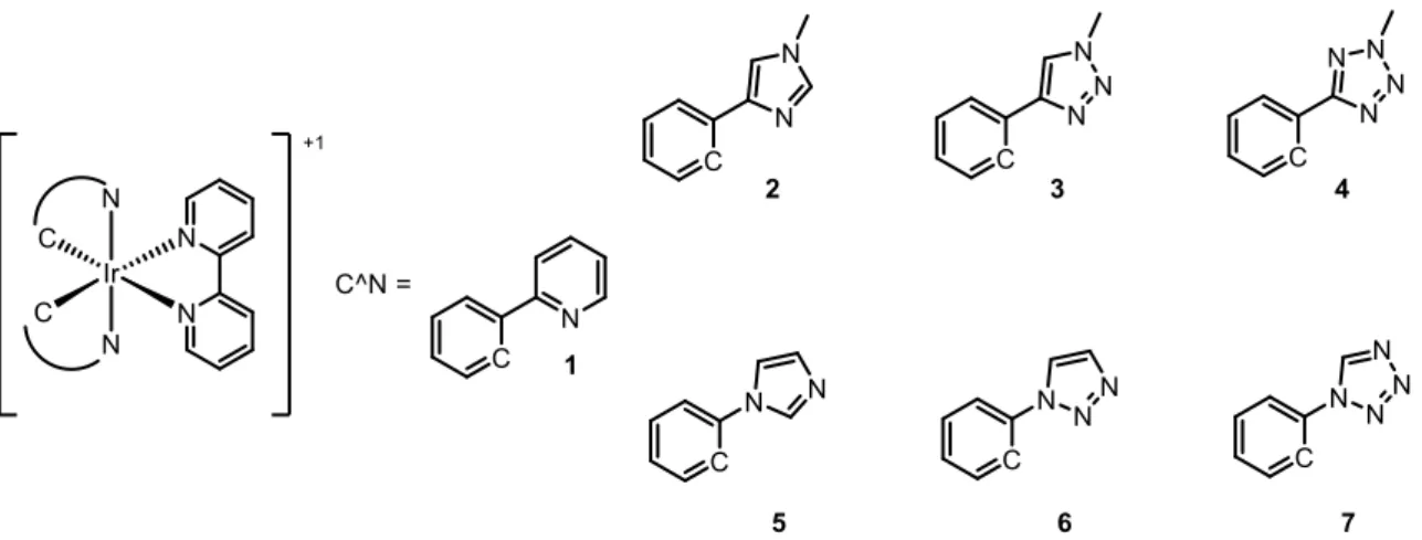
12 In order to improve blue emission from cyclometalated Iridium(III) complexes, J. Ortì and co-workers16 theoretically studied different families of cationic cyclometalated Ir(III)
complexes, by density functional theory (DFT). The aim of their work was to investigate the effect that the number and the position of the nitrogen atoms have on the complexes emission. For this purpose, the authors choose Iridium(III) complex 1 as reference (Figure 9) and calculated both the energy frontier molecular orbitals (HOMO and LUMO) and relative energy of the lowest-lying triplet electronic states. Then, two series of different complexes have been studied: in first, named C series or “regular series” (2, 3, 4), presents the phenyl group directly linked to a C atom of the N-containing heterocyclic ring, while the second, called N series or “irregular series” (5, 6, 7) show the phenyl linked to a N atom the N-containing heterocyclic ring, as shown in Figure 9.
Figure 9 – Ionic Iridium (III) complexes and the two families of ligands
Calculations show that the atomic orbital compositions of the frontier MOs are very similar for all the complexes. The HOMO is mainly centered on the Ir(III) metal center and on the phenyl moiety of the cyclometalating ligands, while the orbitals of ancillary ligand haven’t any influence. Instead, the LUMO is centered on the π* orbitals of the ancillary ligand, and have a very small contribution from the metal. In Figure 10 a schematic representation of the calculated energies of the frontier molecular orbitals of all the studied complexes is reported.
13
Figure 10 - Schematic representation of the energies calculated for the frontier molecular orbitals
The higher stabilization effect amounts to 0.65 eV for the HOMO in passing from 1 to 7. Graphic 1 shows the theoretical emission of each complex:
Graphic 1- Theoretical emission of the complexes
Analysing the theoretical data it is evident that increasing in the number of nitrogen atoms on the azole ring of the C^N ligands, leads to a stabilization of the HOMO and to an expansion of the HOMO-LUMO energy gap of the complex. Moreover calculations also show that the position of the aryl moiety (linked to a C or N atom of the N-heterocycle ring), plays a relevant role in determining the emission energy too. Complexes of the “irregular series” present the larger HOMO-LUMO gap and a significant blue-shifted emission, compared to the equivalent regular form.
14
3 P
URPOSE OF THE WORKAs illustrated in the previous sections, the synthesis of blue-emitting metal complexes is a very challenging goal. With this target in mind and taking into account the previously reported theoretical studies,16 we planned the synthesis of the series of new cyclometalated
Iridium(III) complexes reported in Figure 11, in collaboration with Dr. Nicola Armaroli group (CNR, Bologna). In detail, we wanted to use various cyclometalating ligands containing an increasing number of nitrogens in inverse and regular position. Moreover, in order to maximize the blue emissions of the final complexes, we planned to use t-butyl isocyanide as ancillary ligand.15
Figure 11 – Regular and Irregular target Iridium(III) complexes
The work was planned according the following steps. Initially the synthesis of the ligands should be designed and performed. Then the obtained ligands should be employed to set up appropriate procedures to give the corresponding complexes. The eventually obtained complexes should be carefully purified and completely characterized, both from chemical, spectral and photophysical point of view.
15 Finally, a correlation between the structure of the complexes and their emitting properties could be formulated analysing and comparing the photophysical data of the real compounds.
16
4 R
ESULTS ANDD
ISCUSSIONComplexes N2 and C4 have been already obtained by the research group where I worked for my thesis, as illustrated below.
The synthesis of N2 was reported in the following Scheme 1:17
Scheme 1 – N2 Synthesis
The reaction of commercially available ligand 5 with IrCl3·xH2O in a mixture of refluxing
2-ethoxyethanol and H2O, following the general procedure reported by Nonoyama21 gave
the cyclometalated Dimer [(5)2Ir(µ-Cl)]2 within 16 hours. The dimer was reacted with
tert-butyl isocyanide (tBuNC), after treatment with silver triflate in order to remove the
chloride anion and let the coordination of two monodentate ligands. After purification by column chromatography on silica and recrystallization, N2 was obtained as an air- and moisture-stable white solid in 74% yields.
At room temperature, N2 exhibits blue phosphorescence with λmax = 428 nm and Φ
(quantum yield) ≈0.1%.
On the other hand, the synthesis of C4 was much more demanding.15 Repeated attempts to obtain the classical dichloro-bridge dimer [(C^N)2Ir(μ-Cl)]2 by direct reaction of
IrCl3·xH2O with 2-methyl-5-phenyltetrazole 4 as cyclometalating ligand following the
reported literature proceduresfailed. For this reason, a further step was introduced in order to promote the cyclometalation step (Scheme 2).
17
Scheme 2 – C4 synthesis
Ligand 4 was reacted with IrCl3·xH2O in refluxing 2-ethoxyethanol/H2O. The obtained
complex, which structure was unknown, was reacted with AgBF4 in order promote the
cyclometalation. The resulting cyclometalated crude Iridium(III) complex was dissolved in ACN and then crystallized to give the solvato complex as colorless crystals (Scheme 2). Finally, it was dissolved in a mixture of DCM/EtOH and tBuNC was added and the mixture was left to stir overnight. Then, the solvent was evaporated and the residue solid was precipitated in Et2O to give pure complex C4.
As regard emission properties, it present blue phosphorescence at room temperature with λmax = 442 nm and quantum yield Φ ≈0.5%.
18 Since two of the six complexes of the series reported in Figure 12 have been already synthetized, I focused my work on the synthesis of the remaining four complexes, i.e. C2,
C3, N3 and N4.
Therefore, my first challenge was to synthesise the four different ligands reported in Figure 13.
Figure 12 –Target ligands
4.2.1 Synthesis of 2
Scheme 3
The first ligand that has been prepared was 1-methyl-4-phenyl-1H-imidazole (2). The synthesis was achieved by direct methylation of commercial 4-phenyl-1H-imidazole, as reported in Scheme 3.18 Cs2CO3 was used as base, with the function of the removal the
acidic proton of the imidazole, in order to activate the nucleophile in the SN2 reaction.
Hence, in five hours this reaction gave 2 in moderate yield (56%) as white solid. The product was fully characterized by 1H and 13C NMR.
19
4.2.2 Synthesis of 3
Scheme 4
The synthesis of ligand 3, 4-phenyl-1-methyl-1,2,3-triazole, was achieved by a one-pot copper(I)-catalyzed alkyne-azide cycloaddition (CuAAC) procedure, starting from the methyl iodide (Scheme 4).19 The first step of the reaction concerns the formation of the methylazide that was not isolated. Then phenylacetylene was added, followed by 2,6-lutidine, the catalyst CuSO4*5H2O, and Sodium Ascrobate, the reducing agent. The
reaction was completely regioselective and gave the desired 1,2,3-triazole 3, that was purified by column chromatography on silica gel and collected as a yellow solid in 62% yields. The product was fully characterized with 1H and 13C NMR experiments.
4.2.3 Synthesis of 6
Scheme 5
Ligand 6, 1-phenyl-1H-1,2,3-triazole, was prepared through a Cu-catalyzed cycloaddition reaction between phenyl azide and TMS-acetylene. The azide was prepared in situ following a literature reported procedure:20 aniline was reacted with t-BuONO and TMSN3
at 0°C, leaving it warming to room temperature within 16 hours. The reaction proceeded smoothly and the second step was performed without isolation of the intermediate of the first step. The mixture was dried in vacuum and the crude residue was dissolved in
20 methanol/water (1:1). Then TMS-acetylene was added to the solution, follow by CuSO4*5H2O and Sodium Ascorbate. Moreover, K2CO3 was added, in order to perform
the deprotection of the TMS group in the formed structure. After the work-up, the mixture was purified by silica gel column chromatography to afford 6 in 66% yield as brown solid. The product was fully characterized by 1H and 13C NMR.
4.2.4 Synthesis of 7
Scheme 6
The procedure for the synthesis of 1-phenyl-1H-tetrazole 7 involved the addition of aniline, sodium azide and triethyl orthoformate to acetic acid. Initially the solution was opaque yellow. The mixture was refluxed for 6 hours, after which the solution became clear yellow. The mixture was cooled to room temperature, quenched with water and sodium carbonate was added until the gas evolution ceased. The formed precipitate was filtered off, washed with water and dried under vacuum. The ligand was obtained in 62% yields and characterized with 1H and 13C NMR.
21 The most common route to obtained cyclometallated Ir(III) complexes consists in two steps. The first one involves the preparation of a cyclometallated Ir(III) dimer, while the second one entails the reaction between the obtained dimer and an ancillary ligand or a further cyclometalating ligand, in order to form the desired complex.
Nonoyama and co-workers published in 1974 a way to prepare the intermediate dimer A,21 by reaction of iridium trichloride with two equivalent of C^N ligand as reported in Scheme 7. The reaction of dimer A with a bidentate N^N ligand let to obtain a cationic cyclometalate Ir(III) complex, as shown by the plethora of examples reported in the literature.
Scheme 7 – General synthesis of heteroleptic Iridium complexes B
Concerning the formation of the dimer, 2-phenyl pyridine derivatives are the most used cyclometalating ligands. However, increasing the number of nitrogen in the heterocyclic ring lead to some difficulties in the cyclometalating step. For instance, as previously mentioned, the use of 5-phenyl tetrazole as cyclometalating ligand for the synthesis of C4 required special reaction conditions; on the other hand, cyclometalation with 4-phenyl-1,2,3-triazoles derivatives gave complex mixtures of dimers, that were not always characterized, as independently reported by Schubert22 and De Cola23 research groups. However, the goal of my work was to develop suitable procedures to obtain the series of Ir(III) complexes reported in Figure 11, and the complete elucidation of the intermediate structures was not essential.
In order to set up a convenient procedure for the synthesis of complex C3, I performed some preliminary tests following the previously reported methods with
1-methy-4-phenyl-22 1,2,3-triazole 3 as cyclometalating ligand and 2,2’-bipyridine as ancillary ligand, that generally let to smoothly obtain the desired complex, because of its chelating nature. As first, ligand 3 was reacted with IrCl3·xH2O in 2-ethoxyethanol and water, in accordance
with the Nonoyama’s procedure, as reported in Scheme 8:
Scheme 8-
After refluxing 24 hours, the mixture was cooled at room temperature and the obtained solid was filtered off. The 1H NMR analysis of the crude intermediate solid shows a
complicated pattern of signals and, therefore, the structure of the solid wasn’t further investigated. The obtained product was used as starting material for the next step.
Two procedures were tested to determine the best conditions to carry out the synthesis of
C3.
Method A) Schubert procedure
The isolated solid derived from the previous step was dissolved in a mixture of DCM and methanol (3:1), then an excess of 2,2’-bipyridine was added and the mixture was refluxed under nitrogen for 24 hours, in agreement with Schubert procedure22 (Scheme 9).
23 Then the solvent was evaporated and the residue was dissolved in few millilitres of DCM and precipitated with diethyl ether. The resulting solid was characterised by 1H and 13C
NMR experiments, revealing the formation of the desired product in 76% yield.
Method B) De Cola procedure
Following the methodology reported by De Cola et al.23 the solid derived from the
cyclometalation step, was dissolved in ACN, and the resulting yellow solution was refluxed for 24 hours under inert atmosphere (Scheme 10). After that time, the solution was dried in vacuum and the obtained solid was dissolved in a mixture of 2-ethoxyethanol and water (3:1) and an excess of 2,2’-bipirydine was added. The reaction was left to stir 24 hours at reflux and then the solvent was evaporated. The obtained solid was dissolved in few millilitres of DCM and precipitated with diethyl ether. The resulting solid obtained in 65% yield showed the same peaks at 1H and 13C NMR analysis of the previously prepared complex.
Scheme 10 – De Cola procedure
As shown, both methods gave the desired complex within good yields and comparable purity. The only differences reside in the reaction conditions: method A requires fewer steps and milder conditions than method B; so I decided to fellow method A reaction conditions for the synthesis of C3.
24
4.3.1 Synthesis of C
3Since the aim of my work is to obtain a series of complexes with emission properties shifted in the blue region as much as possible, I used t-BuNC as ancillary ligand, as discussed above. However, owing the monodentate nature of this ligand, a further synthetic step involving a Ag(I)-mediated halide extraction has to be introduced. The yellow solid obtained by refluxing two equivalent of 3with IrCl3·xH2O in 2-etoxhyethanol/H2O was
reacted with AgPF6 in DCM/MeOH for 16 hours at reflux under nitrogen atmosphere
(Scheme 11), then the solid was filtered off, the solvent evaporated and the obtained residue was finally treated with t-BuNC in DCM/EtOH overnight. After that time, the solvent was evaporated, and the solid was dissolved in a few millilitres of DCM and precipitated by addition of diethyl ether, affording the desired complex. The obtained C3 has been fully characterized with 1H NMR, 13C NMR, 19F NMR and mass spectra (ESI).
Scheme 11
The 1H NMR spectrum is consistent with the expected structure of C3. The singlet at 8 ppm corresponds to the two protons on the two triazole rings, then the four groups of distinct signals (doublet, triplet, triplet and another doublet) in the aromatics area correspond to the four protons on each of the two cyclometalated phenyl rings. The singlet at 4.25 ppm refers to the two equivalent N-methyl groups. Finally, at 1.40 ppm there is the singlet of the two t-butyl groups on the isocyanides
25
NMR spectra 1 – 1H experiment C
3
4.3.2 Synthesis of C
2Based on the successfully results obtained in the synthesis of C3, we decided to apply the
same synthetic approach for the preparation of C2. In detail, starting from 2, the
intermediate species was prepared by refluxing the Iridium salt in a degassed 2-ethoxyethanol/H2O mixture for 24 hours, (Scheme 12). Next, the obtained solid was
filtered, washed with water and then dissolved in a DCM/MeOH mixture and treated with AgBF4 at reflux for 16 hours. After this time t-BuNC was added and the reaction was left
to stir overnight. Finally, the mixture was treated with NH4PF6 in a counteranion-exchange
reaction, to achieve the complex as PF6- salt. The solution was washed with diethyl ether,
26
Scheme 12
The 1H NMR spectrum shows two singlet at 8.05 and 7.40 ppm that correspond to the two
protons on the two triazole rings. Then four distinct signals (doublet, triplet, triplet and another doublet) in the area of the aromatics correspond to the four protons of each of the phenyl rings. At 1.25 ppm there is the singlet of the two t-butyl groups of the two isocyanides. Despite repeated purification attempts, some unknown impurities are still present in the solid, as can be observed from some broaden signals and the increased value of some integrals in the 1H NMR spectrum.
NMR spectra 2 – 1H experiment C
27
4.3.3 Attempted Synthesis of N
4Concerning N4, repeated attempts to obtain the classical cyclometalated dimer [(7)2
Ir(μ-Cl)]2or a cyclometalated intermediate from ligand 7 and IrCl3·xH2O failed.
In detail, the first attempt involved the same approach previously reported for the synthesis of C2 and C3, using 2,2’-bipyridineas ancillary ligand: 2.5 equivalents of 7 have been
reacted with IrCl3·xH2O in refluxing 2-ethoxyethanol/water 3:1 for 24 hours. Then, the precipitated solid has been isolated and treated with 2,2’-bipyridine in a DCM/methanol (4:5) mixture for 24 hours at reflux in nitrogen atmosphere, as reported in Scheme 13. The resulting solid has been isolated and analysed by NMR. The 1H NMR spectrum of the crude showed the starting ligand as the main product, in mixture with other unknown impurities. The clear result was the lack of cyclometalation.
Scheme 13
In order to promote the cyclometalation step, it was decided to add a reaction step, the treatment with a Silver salt, as for C4.15
15Ligand 7 was therefore reacted with IrCl
3·xH2O in refluxing 2-ethoxyethanol/H2O at
reflux for 16 hours. The obtained intermediate solid was reacted with AgBF4 in DCM for
6 hours at room temperature. After that time, the solution was filtered in order to remove the Ag-derivative and dried under vacuum. The resulting crude was dissolved in a mixture of DCM/EtOH (4:5) and an excess of 2,2’-bipyridine was added. Subsequently, the solvent was evaporated and the residue solid was dissolved in DCM and precipitated with Et2O,
28
Scheme 14
Similarly, 1H NMR experiment shows a complex mixture that we weren't able to identify. However, ligand 7 is reported as a sensitive and reactive compound, poorly stable both in acid and basic environments; so harsh reaction conditions, eventually required to promote cyclometallation could lead to the decomposition of the starting material. Therefore, I continued the research to get Ir(III) complexes of the inverse series starting from ligand 6, which results a more stable compound.
4.3.4 Attempted Synthesis of N
3Unfortunately, also employing ligand 6, repeated attempts to obtain a dimer intermediate [(6)2Ir(μ-Cl)]2 or the desired Ir(III) complex N3-bipy failed, as for the N4.
In Table 1 all the reactions carried out varying the reaction conditions are reported.
29
Table 1
Entry ”Ir” Base Solvent T(°C) Ag Salt
1 IrCl3·xH2O - 2-ethoxyethanol/water (3/1) Reflux -
2 IrCl3·xH2O - 2-ethoxyethanol/water (3/1) Reflux AgBF4
3 IrCl3·xH2O K2CO3 ACN Reflux AgBF4
4 IrCl3·xH2O K2CO3 Glycerol 180 -
5 IrCl3·xH2O K2CO3 Ethylene Glycol 180 -
6 [Ir(COD)(μ-Cl)]2 - 2-ethoxyethanol/water (3:1) Reflux AgBF4
Motivated by the good results obtained in the synthesis of C2 and C3, the first attempt to get a cyclometalated Ir(III) complex of 6 involved the same procedure developed for such complexes (Table 1, entry 1). Thus, ligand 6 was added to a mixture of 2-ethoxyethanol and water (3:1), the solution was degassed and IrCl3·xH2O was added. The mixture was
stirred 16 hours at reflux, then water was added to the cooled mixture. The formed solid was filtered and dissolved in a DCM/MeOH (4:5) mixture, then an excess of 2-2’-bipyridine was added. The mixture was stirred at reflux for 24 hours, the solvent removed and the crude was submitted to NMR analysis, which revealed the absence of cyclometalation. Therefore a silver salt was added after the first step, with the aim to promote proton abstraction and consequent cyclometalation (Table 1, entry 2). Also in this case the experiment failed.
Since it was clear that the troublesome step was the cyclometalation of the ligand, K2CO3
as base was added,24 (Table 1, entry 3). Also in this case, no signals of the desired product were observed in the 1H NMR spectrum.
Therefore, we tried to move on and overcome the cyclometalation problem by performing the reaction at higher temperature. Typical procedures reported for the synthesis of homoleptic complexes was tested, in order to use stronger conditions. As first attempt (Table 1, entry 4), glycerol was used as solvent, and K2CO3 was added to the reaction
mixture. The solution was stirred at 180°C, and after that time a black tarry and stinky solid was separated by filtration. The crude solid was dissolved in a mixture of DCM and methanol (3:1), then an excess of 2,2’-bipyridine was added and the solution was refluxed under nitrogen for 24 hours. After solvent evaporation, the resulting crude showed a
30 complex 1H NMR spectrum lacking of signals that can be attributed to the desired
compound.,
In a further attempt (Table 1, entry 5), Ethylene Glycol was used as solvent, and the reaction was performed at 180°C in presence of a base, K2CO3. After 24 hours, a black
powdery solid was formed, and it was isolated by filtration. The crude solid was dissolved in a mixture of DCM and methanol (3:1), then an excess of 2,2’-bipyridine was added and the solution was refluxed under nitrogen for 24 hours. 1H NMR shows a complex mixture again. So, even these two pathways failed.
As last test (Table 1, entry 6), it was tried to perform the reaction using a more reactive Ir-source, [Ir(COD)(μ-Cl)]2. In order to form the Bis(1,5-cyclooctadiene)diiridium(I),25
IrCl3·xH2O was reacted with 2.5 equivalents of 1,5-cyclooctadiene (COD)in a refluxing
ethanol/water (2:1) mixture for 24 hours. After that time, a red-brick solid precipitate that was isolated by filtration in satisfactory yields. The obtained [Ir(COD)(μ-Cl)]2 was then
reacted in a 2-ethoxyethanol/water (3:1) mixture in presence of 2 equivalent of ligand 6 for 16 hours at reflux. After that time, the mixture was extract with DCM. The organic phase was concentrated, and the obtained crude was reacted with AgBF4 in DCM/MeOH
at reflux in inert atmosphere for 16 hours. After that time, the solution was filtered off, in order to remove the Ag-derivatives, and dried in vacuum. The obtained solid was dissolved in DCM and an excess of the 2,2’-bipirydine was added. The mixture was stirred for 24 hours at reflux.
Similarly to the previous experiments, the 1H NMR spectrum didn’t show any trace of the desired cyclometalated product.
4.3.5 Synthesis of N
3FIn a work published by Y. Ma et al. in 2014, 26 the use of a fluorinated ligand for the
synthesis of luminescent complexes is reported. In the paper, a better yield for a bi-F-functionalized triazole derivatives toward the mono-F-bi-F-functionalized in the synthesis of the final complexes is described. Therefore, we decided to prepare a new ligand (Figure 13), 6F, where the phenyl group is decorated with an F atom, trusting it could facilitate the
31
Figure 13 – From 6 to 6F
The same procedure of the synthesis of 6 was employed to obtain ligand 6F, with p-fluoroaniline as starting material (Scheme 16). Thus, p-p-fluoroaniline was reacted in ACN in the presence of t-BuONO and TMSN3 at 0°C, leaving it warm to room temperature
within 16 hours. After this time, the solvent was removed and the crude was dissolved in a methanol/water (1:1) mixture. Then, TMS-acetylene was added, followed by CuSO4*5H2O and Sodium Ascorbate. Moreover, K2CO3 was added in order to directly
perform the deprotection of the TMS. Since NMR analysis on the obtained crude shows the presence of the TMS group linked to the formed triazole-ring, the solid was dissolved in ACN and treated with AgF. The mixture was stirred for 16 hours at room temperature. Insoluble Ag-derivative were filtered off through celite. Subsequently the solution was dried in vacuum and the crude was purified by silica gel column chromatography to afford
6F in low yield (7.3%) as brown solid.
Scheme 16
I was able to test a single route with this new ligand, following the classical procedure as reported in Scheme 17.
32
Scheme 17
Ligand 6F was reacted with IrCl3·xH2O in refluxing 2-ethoxyethanol/H2O. After 16
hours, a solid is formed, and it was collected by filtration. Then, it was dissolved in a DCM/MeOH (4:5) mixture and an excess of 2,2’-bipyridine was added. The mixture was stirred at reflux for 24 hours in nitrogen atmosphere. After that time, the solvent was removed and the crude was submitted to NMR analysis, which revealed the absence of cyclometalation.
33
5 C
ONCLUSIONThe aim of my work was very ambitious, and I spent most of the time of the internship in performing synthetic experimental work in the lab and actually the project is still in progress.
I had successfully synthesized all of the designed ligands 2, 3, 6 and 7 in good yields and purity. I have developed an efficient synthetic method for the preparation of two cationic Iridium(III) cyclometalated complexes, C2 and C3, starting from the two ligands of the C- or regular, series, i.e. 2 and 3.
Unfortunately, any attempt to get cyclometalated complexes N3 and N4 from the N-ligands
6 and 7 failed. A wide screening of reaction conditions involving ligand 6 gave completely
unsatisfactory results. Studies are in progress to find a viable route to these remaining complexes. Afterwards, a complete photophysical characterization of the designed complexes would be performed, in order to find a possible correlation between their structure and their emitting properties.
34
6
E
XPERIMENTALS
ECTION1H, 13C, NMR spectra were recorded on a Varian AS 300, on a Mercury 400 or a Varian
AS 600 spectrometer.
Chemical shifts (δ) are reported in ppm relative to residual solvent signals for 1H and 13C NMR: Solvent 1H NMR (ppm) 13C NMR (ppm) CDCl3 7.26 77.0 CD2Cl2 5.25 54.0 DMSO 2.50 39.5 CD3OD 4.78 49.2
13C NMR spectra were acquired with 1H broadband decoupled mode. The types of carbon
atoms were determined by DEPT NMR experiments. To indicate the multiplicity were used the following abbreviations: s, singlet; d, doublet; t, triplet; q, quartet; m, multiple.
Analytical grade solvents and commercially available reagents were used as received, unless otherwise stated. Chromatographic purifications were performed using 230-400 mesh silica.
35
Scheme 18
Synthesis of 1-methyl-4-phenyl-1,2,3-triazole (3): Iodomethane (0.345 mL, 5.5 mmol)
and sodium azide (320 mg, 5 mmol) were combined in dimethyl sulfoxide (7.5 mL). The mixture was stirred at room temperature for four hours. Then the reagents were added to the reaction mixture in the order: water (3.5 mL), phenyl acetylene (0.6 mL, 5.5mmol), sodium ascorbate (118 mg, 0.6 mmol in 1 mL of water), copper sulfate pentahydrate (17.5 mg, 0.07 mmol in water), and in last 2,6-lutidine (0.65 mL, 5.5 mmol). The mixture was stirred at room temperature for 12 hours. The reaction mixture was then diluted with water (12.5 mL) and the solid filtered and washed with water (12.5 mL) and dilute ammonia 5% (12.5 mL). The solid was air dried and washed with diethyl ether. This gave 4-phenyl-1-methyl-1,2,3-triazole (490 mg, 62% yield). 1H NMR (300 MHz, CDCl 3) δ 7.81 (dd, J1 = 1.4 Hz, J2 = 7.3 Hz, 2H), 7.73 (s, 1H), 7.45-7.38 (m, 2H), 7.35-7.29 (m, 1H), 4.11 (s, 3H). 13C NMR (75 MHz, CDCl 3) δ 147.9 (C), 130.5 (C), 128.8 (CH), 128.1 (CH), 125.6 (CH), 120.6 (CH), 36.7 (CH3).
36
Scheme 19
Synthesis of 1-methyl-imidazole (2): To a solution of
4-phenyl-1H-imidazole (720 mg, 5 mmol) in N-N-dimethylformamide (12 mL) containing cesium carbonate (2.18 g, 6.7 mmol) was added iodomethane (0.345 mL, 5.5 mmol). The white solution was stirred at room temperature for 5 hours. Then the reaction mixture was washed with water, brine and dried over Na2SO4, filtered and concentrated. Purification by flash
column chromatography on silica gel (DCM:MeOH=95:5) gave 1-methyl-4-phenyl-1H-imidazole 2( 470mg, 60% yield ) as a white solid.
1H NMR (400 MHz, CDCl 3) δ 7.76 (dd, J1 = 1.3 Hz, J2 = 8.4 Hz, 2H), 7.44 (s, 1H), 7.36 (t, J = 7.9 Hz, 2H), 7.23 (tt, J1 = 1.3 Hz, J2 = 7.4 Hz, 1H), 7.15 (s, 1H), 3.68 (s, 3H). 13C NMR (100 MHz, CDCl 3) δ 142.4 (C), 137.9 (CH), 134.2 (C), 128.5 (CH), 126.6 (CH), 124.7 (CH), 115.8 (CH), 33.4 (CH3).
37
Scheme 20
Synthesis of 4-phenyl-1H-tetrazole (7): To a solution of aniline (0.91 mL, 10 mmol), was
added: sodium azide (1.33 g, 20 mmol), triethyl orthoformate (5 mL, 30 mmol), and finally glacial acetic acid (4.6 mL, 80 mmol). The yellow solution was stirred at 80°C for 6 hours. Than the reaction mixture was washed with water, brine and dried over Na2SO4, filtered
and concentrated. Purification by flash column chromatography on silica gel (DCM:MeOH=95:5) gave 1-methyl-4-phenyl-1H-imidazole 7( 0.877 g, 60% yield ) as a white solid 1H NMR (400 MHz, CDCl 3) δ 9.01 (s, 1H), 7.72 (d, J = 7.6 Hz, 2H), 7.59 (tt, J1 = 2.0 Hz, J2 = 7.4 Hz, 2H), 7.54 (tt, J1 = 2.0 Hz, J2 = 7.6 Hz, 1H). 13CNMR (100 MHz, CDCl 3) δ 140.5 (C), 133.8 (CH), 130.2 (CH), 130.0 (CH), 121.2 (CH).
38
Scheme 21
Shyntesis of 1-phenyl-1H-1,2,3-triazole (6) : In a solution of aniline (947 µL, 10 mmol,
1 eq.) in ACN (25 mL) at 0°C was added dropwise t-BuONO (1.612 g, 1.9 mL, 15 mmol, 1.5 eq.) followed by addiction of trimethylsilyl azide (1.451 g, 1.66 uL, 12 mmol, 1.2 eq.). The yellow solution changes color towards orange. The reaction was stirred at room temperature for 48 h. Then the mixture was concentrated in vacuo. In the same flask was added MeOH/H2O (1:1, 14 mL), trimethylsylilacetilene (2.12 mL, 15 mmol, 1 eq.),
potassium carbonate (1.65 g, 1.2 eq.), copper sulfate pentahydrate (500 mg, 2 mmol, 0.2 eq.) and finally sodium ascorbate (0.865 g, 4 eq.). The reaction was stirred at room temperature for 24 hours. The yellow solution changes color towards brown and gases was products. After one hour color changes again to red.
Upon completion of the reaction, aqueous ammonium hydroxide (28%) was added to the reaction mixture, the organic layer was separated, and the aqueous layer was extracted with EtOAc (3 times). The combined extracts were washed with water (twice) and brine and dried over Na2SO4. The solvent was filtered off and evaporated under reduced pressure.
The crude residue was purified by column chromatography on silica gel (exhane : ethyl acetate= 8:2) like yellow oil, , which some minutes it became a yellow solid.
1H NMR (300, MHz, CDCl 3): δ 8.00 (d, J = 1.1 Hz, 1H), 7.86 (d, J = 1.0 Hz, 1H), 7.75 (dd, J1 = 1.5 Hz, J2 = 7.5 Hz, 2H), 7.54 (tt, J1 = 1.7 Hz, J2 = 8.2 Hz, 2H), 7.45 (tt, J1 = 1.6 Hz, J2 = 7.7 Hz, 1H). 13C NMR (75 MHz, CDCl 3) δ 180.2 (C), 134.5 (CH), 129.8 (CH), 128.8 (CH), 121.7 (CH), 120.7 (CH).
39
Scheme 22
Synthesis of 1-(4-fluorophenyl)-1H-1,2,3-triazole (6F): In a solution of p-fluoroaniline (910 µL, 10 mmol, 1 eq.) in acetonitrile (25 mL) at 0°C was added dropwise t-BuONO (1.9 mL, 15 mmol, 1.5 eq.) followed by addiction of trimethylsilyl azide (1.6 mL, 12 mmol, 1.2 eq.). After an hour, the color changes to red. The reaction was stirred at room temperature for 16 hours. Then the mixture was concentrated in vacuum. In the same flask was added in first the solvent MeOH/H2O (1:1, 14 mL), in second trimethylsylilacetilene
(2.12 mL, 15 mmol, 1 eq.), then potassium carbonate (1.65 g, 1.2 eq.), copper sulfate pentahydrate (500 mg, 2 mmol, 0.2 eq.) and finally sodium ascorbate (0.865 g, 4 eq.). The reaction was stirred at room temperature for 24 hours. The yellow solution changes color towards brown and gases was products.
Upon completion of the reaction, aqueous ammonium hydroxide (28%) was added to the reaction mixture, the organic layer was separated, and the aqueous layer was extracted with DCM (3 times). The combined extracts were washed with water (twice) and brine and dried over Na2SO4. The solvent was filtered off and evaporated under reduced pressure.
The crude residue was treated with AgF (excess) in ACN. After that time, the mixture was filtered and evaporated under reduced pressure. The solid so obtained was purified by column chromatography on silica gel (exhane : ethyl acetate= 8:2) like yellow oil, , then it was cooled to room temperature and it became a yellow solid.
1H NMR (400, MHz, CDCl 3) δ 7.97 (d, J = 0.9 Hz, 1H), 7.85 (d, J = 0.9 Hz, 1H), 7.76-7.70 (m, 2H), 7.27-7.20 (m, 2H). 13C NMR (100 MHz, CDCl 3) δ 163.7 (C), 161.2 (C), 134.6 (CH), 122.7 (CH), 122.6 (CH), 110.9 (CH), 116.8 (CH), 116.6 (CH).
40
Scheme 23
Synthesis of Ir(III) Complexes C3-Bipy (Schubert): 1-methyl-4-phenyl-1,2,3-triazole (40 mg, 0.25 mmol, 2.5 equiv.) and IrCl3·xH2O (30 mg, 0.1 mmol) were reacted for 12
hours in degassed 2-ethoxyethanol/water (4 mL, 3:1 ratio) under reflux. Reached 130°C a yellow solid begins to form. After cooling to room temperature, the solution was filtered and washed with water and dried. A mixture of DCM and methanol (1+1.2 mL) was stirred for 15 minutes under N2 atmosphere, after that the solution was degassed the precursor
complex (1.0 equiv) and 2,2’-bipyridine ( 26 mg, 6.0 equiv), respectively, were added. The reaction mixture was stirred for 14 hours under reflux excluding light. After cooling to room temperature NH4PF6 (5 equiv) was added, and the mixture was stirred overnight. The
solvents were removed under reduced pressure, and the residue was dissolved in DCM (15 mL). The solution was washed with water and dried over Na2SO4. The concentrated DCM
solution was precipitate with diethyl ether, and the precipitating solid was isolated.
1H NMR (300, MHz, CDCl
3) δ 8.47 (d, J = 8.8 Hz, 1H), 8.10 (d, J = 5.4 Hz, 1H), 8.05 (td,
J1 = 5.4 Hz, J2 = 8.0 Hz, 1H), 7.76 (s, 1H), 7.41 (dd, J1 = 1.3 Hz, J2 = 7.6 Hz, 1H),
7.38-7.31 (m, 1H), 6.97 (dt, J1 = 1.2 Hz, J2 = 7.1 Hz, 1H), 6.86 (dt, J1 = 1.3 Hz, J2 = 7.2 Hz,
41
Scheme 24
Synthesis of Ir(III) Complexes C3-Bipy (De Cola): 2 1-methyl-4-phenyl-1,2,3-triazole (40 mg, 0.25 mmol, 2.5 equiv) and IrCl3·xH2O (30 mg, 0.1 mmol) were reacted for 12
hours in degassed 2-ethoxyethanol/water (4 mL, 3:1 ratio) under reflux. Reached 130°C a yellow solid begins to form. The resulting pale yellow solid was isolated by filtration and washed successively with water (10 mL), yield: 16 mg (56%). The resulting solid was dissolved in 12 mL of ACN, and stirred at reflux for 24 hours under nitrogen atmosphere, in order to form solvato complex. Then one day, the solution was dried under vacuum and used for the next step: 16 mg (0.028 mmol) of complexes precursor and 12 mg (0.08 mmol) of 2,2’-bipyridine were suspended in 2-ethoxyethanol/H2O (6+2mL). The reaction mixture
was flushed with nitrogen for 20 min and refluxed for 17 hours, protected from light. After the mixture cooled, water (15 mL) was added. The mixture was extracted with Et2O (2
times x 20 mL). The aqueous phase was heated at 80 °C to remove traces of Et2O. Addition
of an aqueous solution of NH4PF6 (1 g in 10 mL of water) yielded a yellow precipitated
that was filtered and washed with water (20 mL) and Et2O (20 mL). 1H NMR (300, MHz, CDCl
3) δ 8.47 (d, J = 8.8 Hz, 1H), 8.10 (d, J = 5.4 Hz, 1H), 8.05 (td,
J1 = 5.4 Hz, J2 = 8.0 Hz, 1H), 7.76 (s, 1H), 7.41 (dd, J1 = 1.3 Hz, J2 = 7.6 Hz, 1H),
7.38-7.31 (m, 1H), 6.97 (dt, J1 = 1.2 Hz, J2 = 7.1 Hz, 1H), 6.86 (dt, J1 = 1.3 Hz, J2 = 7.2 Hz,
42
Scheme 165
Synthesis of Ir(III) Complexes C3: 1-methyl-4-phenyl-1,2,3-triazole (40 mg, 0.25 mmol, 2.5 equiv) and IrCl3·xH2O (30 mg, 0.1 mmol) were reacted for 12 hours in degassed
2-ethoxyethanol/water (4 mL, 3:1 ratio) under reflux. Reached 130°C a yellow solid begins to form. After cooling to room temperature, the solution was filtered, washed with water and dried. The resulting solid (30 mg) was dissolved in CH2Cl2 / MeOH( 4 + 5 mL). and
AgBF4 (26 mg) was added, the solution was vigorously stirred and then refluxed for 12
hours. After cooling, the solution was filtered through a paper filter to remove AgCl and was evaporated to dryness. The resulting crude Ir(III) solvato complex was dissolved in CH2Cl2 / EtOH( 3 + 1 mL) and t-butyl isocyanide was added (23 µL), this mixture was
stirred at room temperature under N2 atmosphere for 16 hours. Then the solid was dissolved
in CH2Cl2 / EtOH( 10 + 2 mL) and NH4PF6 (32.6 mg) was added, the reaction was stirred
overnight at room temperature and then the solvent was evaporated. The solid was dissolved in CH2Cl2 and precipitated with Et2O, to give product (20 mg)
1H NMR (400 MHz, CDCl 3) δ 7.94 (s, 2H), 7.35 (d, J = 8.3 Hz, 2H), 6.86 (dt, J1 =1.3 Hz, J2 = 7.5 Hz, 2H), 6.77 (dt, J1 = 1.3 Hz, J2 = 7.5 Hz, 2H), 6.06 (d, J = 7.3 Hz, 2H), 4.30 (s, 6H), 1.36 (s, 18H). 13CNMR (100 MHz, CDCl 3) δ 142.4 (C), 137.9 (CH), 134.2 (C), 128.5 (CH), 126.6 (CH), 124.7 (CH), 115.8 (CH), 33.4 (CH3). 19F NMR (400 MHz, CDCl 3) δ -72.0 (d, J = 719.01 Hz 6F). (ESI-MS+): 674 (M – PF6).
43
Scheme 26
Synthesis of Ir(III) Complexes C2: 1-methyl-4-phenyl-1H-imidazole (40 mg, 0.25 mmol) and IrCl3·xH2O (30 mg, 0.1 mmol) were reacted for 12 h in degassed
2-ethoxyethanol/water (4 mL, 3:1 ratio) under reflux. Reached 130°C a yellow solid begins to form. After cooling to room temperature, the solution was filtered, washed with water and dried. The resulting solid (30 mg) was dissolved in CH2Cl2 / MeOH( 4 + 5 mL). and
AgPF6 (26 mg) was added, the solution was vigorously stirred and then refluxed for 12 h.
After cooling, the solution was filtered through a paper filter to remove AgCl and was evaporated to dryness. The resulting crude Ir(III) solvato complex was dissolved in CH2Cl2
/ EtOH( 3 + 1 mL) and t-butyl isocyanide was added (23 uL), this mixture was performed under N2, at room temperature overnight. Then the solid was dissolved in CH2Cl2 / EtOH(
10 + 2 mL) and NH4PF6 (32.6 mg) was added, the reaction was stirred overnight at room
temperature and then the solvent was evaporated. The solid was dissolved in DCM and precipitated with Et2O, to give product (20 mg)
1H NMR (400, MHz, CDCl 3) δ 7.93 (s, 2H), 7.31 (dd, J1 =1.2 Hz, J2 = 7.6 Hz, 2H), 7.20 (s, 2H), 6.89 (dt, J1 = 1.2 Hz, J2 = 7.5 Hz, 2H), 6.67 (dt, J1 = 1.2 Hz, J2 = 7.3 Hz, 2H), 6.28 (d, J = 7.1 Hz, 2H), 4.00 (s, 6H), 1.34 (s, 18H). 13C NMR (75 MHz, CD 3OD) δ 152.2 (C), 149.4 (C), 138.6 (C), 137.9 (CH), 130.5 (CH), 126.2 (CH), 122.2 (CH), 120.1 (CH), 114.2 (CH), 57.7 (C), 39.0 (C), 33.8 (CH3), 29.2 (CH3). 19F NMR (400 MHz, CDCl 3) δ -72.7 (d, J = 710.0 Hz, 6F).
44
Scheme 27
Bis(1,5-cyclooctadiene)diiridium(I) dichloride:To a 150 mL 3-neck flask was added
IrCl3·xH2O followed by addition of 95 % of ethanol, water and 1,5-cyclooctadiene under
nitrogen atmosphere. The resulting mixture was stirred under reflux for 24 h and formed a brick red precipitate. It was allowed to cool to room temperature and filtered. The precipitate was rinsed with cold methanol to remove the trace amount 1,5-cyclooctadiene unreacted. Then the product was dried in vacuum for 8 hours. And [Ir(COD)(μ-Cl)]2 was
45
7 B
IBLIOGRAPHY1 L. Flamigni, A. Barbieri, C. Sabatini, B. Ventura, F. Barigaletti, Top Curr. Chem. 2007,
281, 143.
2 V. W.-W. Yam, C. C. Ko, L. X. Wu, K. M. C. Wong, K. K. Cheung, Organometallics
2000, 19, 1820.
3 V. Amendola, D. Bacchilega, I. Costa, L. Gianelli, M. Montalti, P. Pallavicini, A. Perotti,
L. Prodi, N Zaccheroni, J. Photochem. Photobiol. A.: Chem. 2003, 159, 249.
4 K. A. Belmore, R. A. Vanderpool, J. C. Tsai, M. A. Khan, K. M. Nicholas, J. Am. Chem.
Soc. 1988, 110, 2004.
5 N. D. Silavwe, A. S. Goldman, R. Ritter, D. R. Tyler, Inorg. Chem. 1989, 28, 1231. 6 R. Lalrempuia, N. D. McDaniel, H. Muller-Bunz, S. Bernard, M. Albrecht, Angew. Chem.
Int. Ed 2010, 10, 9765.
7 E. Toth, L. Burai, A. E. Merback, Coord. Chem. Rev. 2001, 216, 363. 8 T. J. Keefe "The Nature of Light”, 2007.
9 N. Holonyak Jr., Lemelson-MIT Prize Winner. Lemenson-MIT Program.
Retrieved August 13, 2007.
10 C. W. Tang, S. A. VanSlyke, Applied Physics Letters 1987, 51, 913.
11 M. A. Baldo, D. F. O’Brien, M. E. Thompson, S. R. Forrest, Physical Review B 1999,
60, 14422.
12 S. Lamansky, P. Djurovich, D. Murphy, F. Abdel-Razzaq, H.-E. Lee, C. Adachi, P. E.
Burrows, S. R. Forrest, M. E. Thompson, J. Am. Chem. Soc. 2001, 123, 4304.
13
http://www.sigmaaldrich.com/technical-documents/articles/material-matters/achieving-high-efficiency.html
14 R. D. Costa, E. Ortí, H. J. Bolink, F. Monti, G. Accorsi, N. Armaroli, Angew. Chem. Int.
Ed 2012, 51, 8178.
15 F. Monti, A. Baschieri, I. Gualandi, J. J. Serrano-Pe
́rez,J. ́M. Junquera-Hernández, D. Tonelli, A. Mazzanti, S. Muzzioli, S. Stagni, C. Roldan-Carmona, A. Pertegás, H. J. Bolink, E. Ortí, L. Sambri, N. Armaroli, Inorg. Chem. 2014, 53, 7709.
16 P. Pla, J. M. Junquera-Hernández, H.J. Bolink, E. Ortí, Dalton Trans., 2015, 44, 8497
46
17 N. M. Shavaleev, F. Monti, R. Scopelliti, A. Baschieri, L. Sambri, N. Armaroli, M.
Grätzel, M. K. Nazeeruddin, Organometallics 2013, 32, 460.
18 S. F. Poon, D. J. St. Jean, Jr., P. E. Harrington, C. Henley III, J. Davis, S. Morony, F. D.
Lott, J. D. Reagan, J. Y.-L. Lu, Y. Yang, C. Fotsch, J. Med. Chem., 2009, 52, 6535.
19 F. Himo, T. Lovell, R. Hilgraf, V. V. Rostovtsev, L. Noodleman, K. B. Sharpless, V. V.
Fokin, J. Am. Chem. Soc. 2005, 127, 210.
20 A. S. Kumar, V. D. Ghule, S. Subrahmanyam, A. K. Sahoo, Chem. Eur. J. 2013, 19,
509.
21 M. Nonoyama, Bull. Chem. Soc. Jpn. 1974, 47, 767.
22 B. Beyer, C. Ulbricht, D. Escudero, C. Friebe, A. Winter, L. Gonzalez, U. S. Schubert,
Organometallics 2009, 28, 5478.
23 J. M. F. Hernandez, C. Yang, J. I. Beltran, V. Lemaur, F. Polo, R. Frohlich, J. Cornil,
L. De Cola, J. Am. Chem. Soc. 2011, 133, 10543.
24 H. Q. Liu, T. C. Cheung, S. M. Peng, C. M. Che, J. Chem. Soc. Comm. 1995, 1787. 25 D. Yang, Y. Long, J. Zhang, H. Zeng, S.Wang, C. Li, Organometallics 2010, 29, 3477. 26 Y. Zhao, J. Tang, H. Zhang, Y. Ma, Eur. J. Inorg. Chem. 2014, 4843.