To my family,
for their unconditional love,
Transport Properties
in Polymer Nanocomposite Membranes
©
Cataldo Simari 2015
PhD Dissertation
Laboratory: PC_SM “Mario Terenzi” Department of Chemistry and
Chemical Technologies - CTC University of Calabria
Ponte P. Bucci, 14D 87036-Rende (CS) Italy
ABSTRACT
The aim of this thesis has been to prepare and characterize innovative composite membranes for polymer electrolyte fuel cells (PEMFCs) applications. Among the different energy conversion devices based on polymer electrolytes, PEMFCs, both hydrogen (DHFC) and direct methanol (DMFC), seems to be one of the most promising clean energy technologies. As electrochemical devices able to directly convert the chemical energy of a fuel into electrical energy, PEMFCs offer interesting advantages in vehicular or portable applications , as the quick start, the high energy conversion efficiency (~ 50%), the reduced environmental impact for the low CO2 emissions (zero in the case where the primary fuel is hydrogen) and the flexibility respect to the fuel, in fact, besides hydrogen (DHFC), they can be fed for example with methanol (DMFC). However, considerable efforts are still needed to be able to achieve satisfactory performance in terms of efficiency, durability and cost for mass deployment of such technology. It is necessary to deal with some problems that concern the electrolyte membrane, such as the degradation of the materials, the low proton conductivity at low relative humidity (RH) and poor mechanical properties at temperature higher than 130 °C.
Therefore, the development of high-performance proton conducting polymer electrolyte membranes is critical for the optimal power density and efficiency a PEMFC can achieve because membrane ohmic loss is the major cause of overpotential in the operational current range of the fuel cell. In recent years, increasing interest has been devoted to the development of high temperature proton conducting polymer
electrolyte fuel cell systems. In fact, most of the shortcomings associated with the
low-temperature PEMFC technology based on perfluorosulfonic acid (PFSA) membranes can be solved or avoided by developing alternative membranes with suitable ionic conductivity and stability up to 150 °C. The increasing the operational temperature would result in increased performance of the cell because of easier and more efficient water management, higher reaction rates to the electrodes, improved CO tolerance by the anode electro-catalysts, faster heat rejection rates and better systems integration.
It has been mentioned the possibility to feed PEMFCs systems with other fuel respect to hydrogen. In particular, direct methanol fuel cells (DMFCs) combine the merits of polymer electrolyte fuel cells fueled by H2 with the advantages of a liquid fuel, such as easy handling and high energy density. However, despite these advantages, also regard this devices there are still technical barriers to overcome for their widespread commercialization such as methanol crossover from anode to cathode through the proton exchange membrane.
From the above, it is thus highly important to enhance the proton conductivity of the electrolyte membrane under low RH in order to accomplish higher PEMFCs performance. On the other hand, is essential to develop polymer electrolytes with reduced methanol cross-over for DMFC.
The work presented in this thesis is the result of a Ph.D. project carried out during a period of about three years from 2012 – 2015, in the Physical Chemistry Soft Matter Laboratory “Mario Terenzi” (PC_SM Mario Terenzi) at the Department of Chemistry and Chemical Technologies in the University of Calabria. The thesis was written as part of the requirements for obtaining the doctor of philosophy degree.
The overall objective of this doctoral thesis was to design, synthesize and evaluate innovative composite electrolytes with specific properties suitable for PEM fuel cells that operate at high temperatures (above 100 ° C ) and low RH and/or with low methanol permeability.
To this purpose, three main classes of materials have been explored as nanoadditives to create nanocomposite membranes: (i) organo-modified TiO2 nanoparticles, (ii) layered materials based on clays (anionic and cationic) and graphene oxide and (iii) hybrids clays-carbon nanotubes. While, as concern the ionomers, perfluorosulfonic acid (Nafion®) and polyaromatic polymers (sulfonated Polyether Ether Ketone and Polybenzimidazole) have been evaluated.
In my doctoral porject an attempt was made to conjugate an intense basic research in order to understand the molecular mechanisms at the basis of ionic conduction in such complex systems, and the design, synthesis and more comprehensive characterization of new nanocomposites with opportune requisites. For this purpose an deep study of the transport properties of the water confined within the electrolyte membranes has been
together to a wide physico-chemical, mechanical and electrochemical characterization in order to achieve a systematic understanding at a fundamental level of the effects of dimensionality, architecture and organization of these nanofillers on the properties of the ionomers and to exploit this knowledge for the preparation of high performance electrolytes.
Some of the electrolytes membranes investigated during my PhD thesis were prepared and studied in the framework of the PRIN Project: NAMED-PEM “Advanced nanocomposite membranes and innovative electrocatalysts for durable polymer electrolyte membrane fuel cells”.
The last part of this thesis concerns a research work arisen from a collaboration with ITM-CNR of the University of Calabria, on the Ion Exchange Membranes for Reverse Electrodialysis (RED) process. Here, the NMR techniques were used to study the water dynamics in anion- and cation- exchange membranes (AEMs and CEMs) in order to achieved additional important insights about the effect of the electrolyte solution, on membrane microstructure and its transport and electrical properties.
The results of this research have been published in scientific international Journals and reported in appendix to the end of the thesis.
During these years I have spent two stages periods abroad:
1) in the “Department of Materials Science and Engineering of the University of Ioannina, Ioannina (Greece)”, where I worked under the supervision of Prof. D. Gournis, my research has been focused on the synthesis of novel carbon-based materials as additives for nanocomposite membranes;
2) in Department of Physics & Astronomy of the Hunter College, New York (USA), where I worked under the supervision of Prof. S. Greenbaumn, I performed the High Pressure NMR investigation of water and methanol transport properties in sPEEK-based nanocomposite electrolytes.
Two scientific papers, based on the results obtained during these stages, have been recently submitted and also reported in appendix.
SUMMARY OF PAPERS
The first two papers deal with the investigation of the transport properties of novel Nafion-based nanocomposite membranes as electrolyte for Direct Hydrogen Fuel Cells (DHFCs). In paper I a new class of hybrid materials based on carbon nanotubes (CTNs) rooted on smectite clay (SWy) has been synthesized and, after opportune side-wall chemical oxidation and organo-functionalization of CNTs, was tested as additive in the polymer matrix. The experimental results demonstrated as this class of hybrid material allow the creation of a well connected path for proton conductivity: a conductivities of 710-2
S cm-1 @ 120 °C and 30% RH has been obtained for membrane containing nanotubes decorated with sulfonic acid groups.
Paper II is a study about the effect on water molecular dynamics of the
dispersion of sulfated Titania nanoparticles within Nafion matrix. In this work, a “two-sites” model for the quantitative analysis of the self-diffusion coefficients data have been also proposed. The presence of the filler has found to improve both the water retention and diffusion in composite membranes with a significant impact in the region of high temperatures and very low water content. On the other hand, the model
proposed allowed a good estimation of the hydration number on both pristine and composite membranes.
In paper III, Polybenzimidazole (PBI) was proposed as alternative electrolyte
for High Temperature PEMFC. In particular, a deep investigation about the effect of the monomer sulphonation on the proton dynamics and the mechanical properties of the membranes has been conducted. The experimental data proved that sulphonation causes the formation of inter-chain crosslinks, resultin in a reduced proton mobility and, consequently, the ionic conductivity.
The fourth and the fifth paper are devoted to the investigation of the effect of 2D-layered additives on methanol cross-over. Nanocomposite membranes were prepared and tested as electrolyte in Direct Methanol FCs (DMFCs). In Paper IV, tailored organo-modified graphene oxide nanolayers bearing sulfonated functional groups were tested as additives in Nafion matrix. A procedure to attempt some preferential orientation of the graphene nanoplatelets in the polymer matrix has been also experienced. It has been proved that the different preparation methods of the
nanocomposites led to characteristic morphology, transport properties and barrier effect to methanol. The resulting membrane showed a significant reduction of the diffusion of methanol and however, a high mobility of the water at high temperatures was still guaranteed.
Paper V refers about the investigation of Nafion-composite membranes
obtained by dispersion of anionic (LDH) and cationic (Laponite) nano-clays within polymer matrix. Nanocomposite membranes showed enhanced water retention
capability and reduced methanol permeability, leading to improved performances of the DMFCs. Remarkable results were obtained on the composite Nafion-LDH.
In Paper VI sPEEK-based membranes have been proposed as alternative
electrolyte for high temperature DMFCs. For the preparation of the nanocomposite membranes, an organically functionalized titania, TiO2-RSO3H, was evaluated as filler. The experimental results demonstrated that sPEEK-based membranes represent an interesting alternative for DMFC application, when opportunely modified with nanoadditives. Remarkable improvements were found when using the sPEEK/TiO2 -RSO3H composite membrane as electrolyte in a DMFC, in terms of reduced methanol crossover and higher current and power density delivered.
Paper VII is devoted to a systematic study, by EIS, about the effect of the
solution concentration on on the electrical resistance of anion- and cation- exchange membranes (AEMs and CEMs) and interfaces (electrical double layer and diffusion boundary layer). In this study, NMR techniques have been applied in order to obtain additional important insights about the effect of the electrolyte solution and membranes fixed charges concentration, on membrane microstructure and its mass and electrical transport properties.
LIST OF PAPERS
1. Nicotera, I., Simari, C., Coppola, L., Zygouri, P., Gournis, D., Brutti, S., Minuto, F.D., Aricò, A.S., Sebastian, D., Baglio, V.
“Sulfonated graphene oxide platelets in nafion nanocomposite membrane: Advantages for application in direct methanol fuel cells”
Journal of Physical Chemistry C, 2014, 118 (42), pp 24357-24368;
2. Fontananova, E., Zhang, W., Nicotera, I., Simari, C., Van Baak, W., Di Profio, G., Curcio, E., Drioli, E.
“Probing membrane and interface properties in concentrated electrolyte solutions” Journal of Membrane Science, 2014, 459, pp 177–189;
3. Nicotera, I., Kosma, V., Simari, C., D’Urso, C., Aricò, A.S., Baglio, V.
“Methanol and proton transport in layered double hydroxide and smectite clay-based composites: influence on the electrochemical behavior of direct methanol fuel cells at intermediate temperatures”,
Journal of Solid State Electrochemistry, 2014, 19 (7), pp 2053-2061;
4. Nicotera, I., Kosma, V., Simari, C., Angioni, S., Mustarelli, P., Quartarone, E.
“Ion Dynamics and Mechanical Properties of Sulfonated Polybenzimidazole Membranes for High-Temperature Proton Exchange Membrane Fuel Cells”,
Journal of Physical Chemistry C, 2015, 119 (18), pp 9745–9753;
5. Nicotera, I., Kosma, V., Simari, C., Ranieri, G. A., Sgambetterra, M., Panero, S., Navarra, M.A.
“An NMR study on the molecular dynamic and exchange effects in composite Nafion/sulfated titania membranes for PEMFCs”,
International Journal of Hydrogen Energy, 2015, 40 (2), pp 14651–14660.
6. De Bonis, C., Simari, C., Kosma, V., Mecheri, B., D’Epifanio, A., Allodi, V., Mariotto, G., Brutti, S., Suarez, S., Pilar, K., Greenbaum, S., Licoccia, S., Nicotera, I.
“Enhancement of proton mobility and mitigation of methanol crossover in sPEEK fuel cells by an organically modified titania nanofillers”,
Under revision in Journal of Solid State Electrochemistry. 7. Simari, C., Potsi, G., Policicchio, A., Perrotta, I., Nicotera, I.
“Hybrids Clay-Carbon Nanotubes for Nanocomposite Membranes with Enhanced Proton Conductivity Under Low Humidification”
Other relevant papers not included in this thesis
Nicotera, I., Oliviero Rossi, C., Simari, C., Turco Liveri, V., Calandra P.
“bis(2-ethylhexyl)phosphoric acid/bis(2-ethylhexyl)amine mixtures as solvent media for lithium-ions: a dynamical study”
In press to Colloids and Surfaces A - DOI: 10.1016/j.colsurfa.2015.11.021
S. Scalese, S., Nicotera I., D’Angelo, D., Filice, S., Libertino, S., Simari, C., Privitera, V.
“Cationic and anionic azo-dye removal from water by sulfonated graphene oxide nanosheets in Nafion nanocomposite membranes”
Submitted to New Journal of Chemistry
Boutsika, L.G., Enotiadis, A., Nicotera, I., Simari, C., Charalambopoulou, G., Steriotis, T.A.
“Nafion nanocomposites using Nanoscale Ionic Materials for high temperature proton exchange membrane fuel cells”
CONTRIBUTIONS TO CONFERENCES
Nicotera, I., Simari, C., Gournis, D.Oral presentation: “The effect of functionalized Graphene Oxide platelets on the
transport properties of proton and methanol in Nafion nanocomposite membranes” GEI 2013- Giornate dell’Elettrochimica Italiana, 22 – 27 September 2013, Pavia, Italy; Fontananova, E., Wenjuan, Z., van Baak, W., Nicotera, I., Simari, C., Di Profio, G.,
Curcio, E., Drioli, E.
Oral presentation. “Probing membranes and interfaces properties by impedance
spectroscopy”
Advances in Science and Engineering for Brackish Water and Seawater Desalination II; An ECI Conference Series, September 29 – October 3, 2013 Cetraro (Calabria), Italy; Nicotera, I., Angjeli, K., Simari, C., Coppola, L., Ranieri G. A.
Oral presentation: “Enhanced Proton Transport and Water Retention in
Nanocomposite Membranes for HT-PEMFCs using Organo-Modified Layered nanostructures”
CIMTEC 2014, 15-19 June 2014- Montecatini Terme, Italy;
De Bonis, C., D’Epifanio, A., Mecheri, B., Cozzi, D., Nicotera, I., Licoccia, S.
Oral presentation: “SPEEK/Functionalized Titanium Oxide Nanocomposite Proton
Exchange Membranes”
CIMTEC 2014, 15-19 June 2014- Montecatini Terme, Italy;
Nicotera, I., Angjeli, K., Simari, C., Kosma, V., Coppola, L., Baglio, V.
Oral presentation: “Layered nanostructures for composites hybrid membranes in fuel
cell application: investigation of water and methanol transport properties” XXV CONGRESSO DELLA SOCIETA' CHIMICA ITALIANA, 7-12 September 2014, Rende (CS), Italy;
Filice, S., D’Angelo, D., Libertino, S., Kosma, K., Simari, C., Gournis, D., Nicotera, I., Barberio, M., Privitera, V., Scalese, S.
Oral presentation: “CNT-TiO2 composites in Nafion membranes for efficient dye degradation in water”
IEEE Nanotechnology Materials and Devices Conference, 12-15 October 2014, Aci Castello, Italy;
Kosma, V., Simari, C., Coppola, L., Ranieri, G.A., Nicotera, I.
Oral presentation: “Hybrid nanocomposite membranes based on lamellar fillers: a
study on methanol and water transport properties for DMFC applications” EmHyTeC2014, 9-12 December 2014, Taormina, Italy;
Rossi, C.O., Calandra, P., Nicotera, I., Simari, C., Ranieri, G.A.
Poster presentation: “Dynamics of the Lithium ion confined in HDEHP/BEEA local
structures as probed by Pulsed Field Gradient NMR”
5th International Colloids Conference, 21 - 24 June 2015, Amsterdam, Netherlands. Nicotera, I., Simari, C., Coppola, L., Ranieri, G.A.
Oral presentation: “Novel Clay-Carbon nanotubes as fillers for hybrid nanocomposite
membranes: a study on water transport properties for PEMFC applications” V Iberian Symposium on Hydrogen, Fuel Cells and Advanced Batteries, 05-08 July 2015, Tenerife, España;
Boutsika, L.G., Enotiadis, A., Nicotera, I., Simari, C., Charalambopoulou, G., Theodore A. Steriotis, T.A.
Poster presentation: “Development of nanocomposite polymer electrolyte membranes
for fuel cell applications using novel nanofillers”
E-MRS Fall Meeting and Exhibit, 15-18 September 2015, Warsaw University of Technology.
CONTENTS
ABSTRACT………..…………i SUMMARY OF PAPERS………v LIST OF PAPERS………vii CONTRIBUTIONS TO CONFERENCES………....ix SECTION I. POLYMER ELECTROLYTE MEMBRANES: OVERVIEW AND APPLICATIONS………11.1 HYDROGEN AND FUEL CELLS………2
1.1.1 Hydrogen as fuel……….2
1.1.2 Fuel cells……….4
1.2 PEMFCs: PROPERTIES AND MATERIALS……….21
1.2.1 Polymers used in the PEM………24
1.2.2 Proton Conduction Mechanisms in PEM………..41
1.2.3 Nanocomposite Electrolyte Membranes………...…………46
1.3 REVERSE ELECTRODIALYSIS: FROM SALINITY GRADIENT TO SUSTAINABLE ENERGY………...53
1.3.1 Salinity Gradient Power (SGP)………...54
1.3.2 Reverse electrodialysis process (RED)………...58
1.3.3 Ion Exchange Membranes for RED………...…..61
References………..64
SECTION II. MATERIALS: FILLER NANOSTRUCTURED AND NANOCOMPOSITES………...69
2.1 NANOFILLERS………70
2.1.1 Graphene and Graphite Oxide………...70
2.1.2 Clays………..78
2.1.3 Carbon Nanotubes (CNTs) and Clay - CNTs hybrid……….83
2.1.4 Layered Double Hydroxide (LDH)………90
2.2 PREPARATION OF NAFION NANOCOMPOSITE MEMBRANES………99
References………...102
SECTION III. RESULTS AND DISCUSSION……….107
3.1 POLYMER ELECTROLYTE FOR DHFC….………...110
3.1.1 SWy-CNTs hybrids for Nafion-based nanocomposites (PAPER I)………..111
3.1.2 Nafion/Sulfated titania membranes for PEMFCs (PAPER II)……….116
3.1.3 PBI-based electrolyte for High Temperature PEM-FC (PAPER III)………122
3.2 NANOCOMPOSITE MEMBRANES FOR DMFC………...129
3.2.1 Carbon-based layered materials in DMFC: a novel strategy to reduce the methanol crossover (PAPER IV)…………...130
3.2.2 Anionic and cationic clays nanocomposites for DMFCs (PAPER V)……...139
3.2.3 sPEEK based electrolyte for DMFC (PAPER VI)……….149
3.3 ION EXCHANGE MEMBRANES FOR REVERSE ELECTRODIALYSIS……157
3.3.1 Ion Exchange Membranes microstructures as a function of the electrolyte solution concentration (PAPER VII)……..158
References………....164
CONCLUSIONS……….167
ACKNOWLEDGEMENTS APPENDIX A ……….173
EXPERIMENTAL TECHNIQUES ………175
4.1 NUCLEAR MAGNETIC RESONANCE (NMR) .……….176
4.1.1 NMR Relaxation Measurements ……….183
4.1.2 Temperature dependence of T1 and T2 ……….186
4.1.3 Self-Diffusion Measurements with NMR ………190
4.1.4 High pressure NMR ……….193
4.2 ELECTROCHEMICAL IMPEDANCE SPECTROSCOPY (EIS) ….………195
4.2.1 Principles and Theory ………..195
4.2.2 Linearity and Steady State of Electrochemistry Systems ……….201
4.2.3 Equivalent Electrical Circuits (EEC) ………203
APPENDIX B
SCIENTIFIC PAPERS ………..211 Paper I: “Hybrids Clay-Carbon Nanotubes for Nanocomposite Membranes with
Enhanced Proton Conductivity Under Low Humidification” ...213
Paper II: “An NMR study on the molecular dynamic and exchange effects in
composite Nafion/sulfated titania membranes for PEMFCs” ………..215
Paper III: “Ion Dynamics and Mechanical Properties of Sulfonated
Polybenzimidazole Membranes for High-Temperature Proton Exchange Membrane Fuel Cells” ………..217
Paper IV: “Sulfonated graphene oxide platelets in nafion nanocomposite membrane:
Advantages for application in direct methanol fuel cells” ……….219
Paper V: “Methanol and proton transport in layered double hydroxide and smectite
clay-based composites: influence on the electrochemical behavior of direct methanol fuel cells at intermediate temperatures” ……….221
Paper VI: “Enhancement of proton mobility and mitigation of methanol crossover in
sPEEK fuel cells by an organically modified titania nanofillers” ……..223
Paper VII: “Probing membrane and interface properties in concentrated electrolyte
SECTION
I
POLYMER
ELECTROLYTE
MEMBRANES:
OVERVIEW
AND
APPLICATIONS
This Section is divided in three main Chapters:
(1) Hydrogen and Fuel Cells;
(2) Proton exchange fuels cells: properties and materials (3) Reverse Electrodialysis;
In the first part concerning the fuels cells is reported a comprehensive overview about the main topic in which polymer electrolyte membranes found application, i.e. the proton exchange membrane fuel cells (PEMFCs) that are one of the most promising clean energy technologies. A review of different fuel cell technologies with their working principles, advantages, disadvantages and suitability for several kind of application are also illustrated.
The second part is devoted to the Reverse electrodialysis (RED) technique, another emerging membrane-based energy conversion process, used to extract electricity by mixing two water streams of different salinities. A brief panning about the aspects related to this particular process is also reported.
1.1
H
YDROGEN AND FUEL CELLS
This Chapter deals with the main aspects related to hydrogen energy and fuel cells. As main topic of my PhD research, particular emphasis is given to fuel cells based on polymeric membranes as electrolyte (PEMFCs). The state of the art and the main shortcomings hampering the large scale diffusion of this technology have been extensively discussed.
1.1.1 Hydrogen as fuel
Today depletion of petroleum-based energy resources, climate change and environmental pollution has turned into a great problem for human. As main route to solve these problems, vast efforts to replace fossil fuels with other energy sources such as its connotation clean fuel have been taken.A promising possibility is to exploit the energy potential of the most plentiful element in the known universe: hydrogen. As known, hydrogen is the simplest element (only one proton and one electron) that constitutes about 75% of all normal matter in the universe and nearly 90% of all atoms. At room temperature and pressure, this diatomic molecule (H2) is colorless, tasteless, odorless, slightly soluble in water and safe even if highly explosive.
Hydrogen combustion with oxygen can generate a huge amount of energy:
2H2 + O2 → 2H2O + 572 kJ/mol
Furthermore, we need to consider that hydrogen has an energy density of 39 kWh kg–1, which means that 1 kg of hydrogen contains 130 times more energy than 1kg of batteries, and at least three times larger than that of other chemical fuels (for example, the equivalent value for liquid hydrocarbons is 13 kWh kg–1). This makes hydrogen universally recognized as a green synthetic fuel that could replace fossil fuel, especially for transport applications. Despite its simplicity and abundance, hydrogen doesn't occur naturally as a gas on the earth. Due to its low density (0.08988 g/L), it is not retained by the force of gravity and thus tends to escape from the terrestrial atmosphere: hydrogen is
is always combined with other elements. Water, for example, that is a combination of hydrogen and oxygen (H2O), can be considered unlimited resources of hydrogen.
Fig 1 shows a clean way, based on hydrogen, to produce energy starting from water and sunlight through the combined action of photovoltaic cells and water electrolysis. Solar panels, wind turbines or any other form of renewables could be used to generate electricity to locally power homes and domestic industries, and any excess electricity can be used for splitting water into hydrogen and oxygen, with the hydrogen stored for later use. The stored hydrogen can then be converted back into electricity or other forms of energy when needed, via a fuel cell or direct combustion. Besides water, hydrogen is the main component of many other organic compounds, notably the “hydrocarbons” that make up many of our fuels such as gasoline, natural gas, methanol and propane[1] from which it can be separated from through the application of heat via a process known as reforming. However, unlike hydrocarbons, hydrogen cannot be destroyed, is carbon-free, non-toxic, and its thermal or electrochemical combustion with oxygen yields nothing but energy and water[2, 3].
Figure. 1. Hydrogen cycle for green generation of electrical power.
Water is the only waste product deriving from hydrogen combustion; this is the great advantage replacing methane, gasoline and other fossil fuels with hydrogen. The combustion of these substances actually produces carbon dioxide (CO2), the main
greenhouse gases in the atmosphere. The increase of carbon dioxide and other greenhouse gases in the atmosphere is believed to be the cause of global warming and numerous environmental and climate problems (such as melting glaciers and rising sea levels). To cope with these environmental threats, the international community has decided to take very important economic measures, e.g., the Treaty on the reduction of greenhouse gas emissions, known as the “Kyoto Protocol”. Unfortunately, even if hydrogen seems to provide the solution to environmental pollution and dwindling fossil fuels[1-3], up to now the “green revolution”, so called because foresees a shift from an economy based on fossils fuels to one based on clean and renewable sources of energy, it has not occurred yet. In fact, the scientific world must still overcome several obstacles in order to make hydrogen become the major energy resource: pure hydrogen is currently more expensive than traditional energy sources; the production efficiency (the amount of energy or feedstock used to produce hydrogen) still needs to be improved; lack of infrastructure able to produce and distribute in a capillary way large amounts of hydrogen and lack of technologies suitable to store it safely.
Nonetheless hydrogen represents a lifeline for the future of our planet: an engine that burns pure hydrogen produces almost no pollution. A system based on hydrogen as fuel provides a path for effectively harvesting renewable energy and a sustainable path for unlimited clean energy in which the inherent energy of the stored hydrogen can be released and converted into electrical energy when needed with the only emission of pure water. All of this can be done by another type of electrochemical device, better known as Fuel Cell.
1.1.2
Fuel cells
Due to their particular properties, Fuel Cells are on the verge of creating a vast revolutionary change in the electricity’s field. A fuel cell is an electrochemical device, which can continuously and directly convert the chemical energy of a fuel, without fuel combustion, into electrical energy. Therefore, in a fuel cell system, the chemical energy related to electrochemical reaction of the fuel with oxidant directly change into water, electricity and heat[4]. Fuel cells are often compared to batteries: both convert the energy
produces electricity as long as fuel (hydrogen) is supplied, never losing its charge. Fig. 2 shows a comparison of fuel cell performance with other energy conversion systems. As it is possible to see, the efficiency of fuel cell systems is in any case higher if compared with conventional system: fuel cell converts up to 40–60% of available fuel to electricity. Beside the high efficiency of energy conversion that allow savings in fossil fuels, comparing a fuel cell with other distributed generation technologies, it offers more others advantages: zero emission, reduced noise pollution, modularity, scalability, quick installation and gives good opportunities for cogeneration operations[5, 6] (increasing the efficiency at 90% with heat recovery). All these aspects render fuel cells preferable over other energy conversion devices and a promising technology for use as a source of heat and electricity for buildings, and as an electrical power source for electric vehicles.
Figure 2. Comparison of fuel cell performance with other energy conversion systems.
Fuel cells operate best on pure hydrogen. But fuels like natural gas, methanol, or even gasoline can be reformed to produce the hydrogen required for fuel cells. Reforming these fuels to create hydrogen will allow the use of much of our current energy infrastructure -gas stations, natural gas pipelines, etc.- while fuel cells are phased in. Some fuel cells even can be fueled directly with methanol, without using a reformer.
Although fuel cells are not a recent development, the use of polymeric membranes as electrolytes has received an incredible impetus in the recent past. It is because of this development that fuel cells are the premier candidates as portable source of power for light duty vehicles and buildings and as replacement for rechargeable batteries[7]. In fact, among the different type of fuel cells, proton-exchange membrane
fuel cells (PEMFCs) are considered to be one of the most promising technology for a
clean and efficient power generation in the twenty-first century. Despite PEMFCs have already found a wide range of applications there are still some barriers that must be overcome to promote their rapid commercialization: developing membrane that complies with the basic requirements of fuel cells and is inexpensive at the same time has been the principal goal of research.
In this section, after a description of the general principles of the Fuel Cells and their classification, we’ll focus our attention on Proton Exchange Membrane Fuel Cells and the proton transport properties of these electrolytes, ending with an analysis of a possible strategy to improve PEMFC performances: the synthesis of composite membranes.
Historical outline
The basic principles of a fuel cell had effectively been demonstrated at the beginning of nineteenth century by Humphry Davy. This was followed by pioneering work on what were to become fuel cells by the scientist Christian Friedrich Schönbein in 1838. However, is William Grove, that is generally credited with inventing the fuel cell in 1839. Grove conducted a series of experiments, which ultimately proved that electric current could be produced from an electrochemical reaction between hydrogen and oxygen over a platinum catalyst[8]. The term fuel cell was first used in 1889 by Charles Langer and Ludwig Mond, who researched fuel cells using coal gas as a fuel, but the technology generally remained obscure.
Figure 3. Historical review of fuel cells[10].
In 1932, Cambridge engineering professor Francis Bacon modified Mond's and Langer's equipment to develop the first Alkaline Fuel Cells (AFC) but it was only in 1959 that Bacon demonstrated a practical 5 kW fuel cell system. In the late 1950s and early 1960s NASA, in collaboration with industrial partners, began developing fuel cell generators for manned space missions. Within this collaboration, Willard Thomas Grubb at General Electric (GE) created the first PEMFC unit. Another GE researcher, Leonard Niedrach, refined Grubb's PEMFC by using platinum as a catalyst on the membranes. The Grubb-Niedrach fuel cell was further developed in cooperation with NASA, and was used in the Gemini space program of the mid-1960s. International Fuel Cells (IFC, later UTC Power) developed a 1.5 kW AFC for use in the Apollo space missions. The fuel cell provided electrical power as well as drinking water for the astronauts for the whole duration of their mission. IFC subsequently developed a 12 kW AFC, used to
provide onboard power on all space shuttle flights. Beginning in the mid-1960s, the research work was focused on further development of various fuel cells for applications like stationary powers and transportations. Prompted by concerns over energy shortages and higher oil prices, in the 1970s, many national governments, mainly USA, Canada and Japan and large companies initiated research projects to develop more efficient forms of energy generation[9] resulting in important advances in Phosphoric Acid Fuel Cell (PAFC) technology, in particular in stability and performance. In the 1990s, attention turned first to PEMFC and Solid Oxide Fuel Cell (SOFC) technology, particularly for small stationary applications, moving then to Direct Methanol Fuel Cell (DMFC), as PEMFC technology was adapted for direct methanol portable devices, and to Molten Carbonate Fuel Cell (MCFC) technologies, for large stationary applications. During the last two decades, due to the increasing concerns on the part of governments, business and consumers over energy security, energy efficiency, and carbon dioxide (CO2) emissions, the attention has turned once again to fuel cells as one of main potential technology capable of delivering energy efficiency and CO2 savings while reducing dependence on fossil fuels. Not surprisingly, fuel cells began to become commercial in a variety of applications in 2007. First they started to be sold to end-users with written warranties and service capability, in particular, thousands of PEMFC and DMFC auxiliary power units (APU) were commercialized in leisure applications, such as boats and campervans, with similarly large numbers of micro fuel cell units being sold in the portable sector in toys and educational kits. Then Honda presented the model FCX Clarity at Los Angeles automobile saloon. This model is available for the consumer since the summer of 2008. This is the first fuel cell vehicle platform-exclusive in the world manufactured in series[10].
The types of Fuel Cells
As already explained, a fuel cell is an electrochemical device able to convert the chemical energy of a reaction directly into electricity with byproduct of water and heat. There are several types of fuel cell but they are all based around a central design. A fuel cell unit consists of a stack, which is composed of a number of individual cells. The structure of a simplified fuel cell is shown in Fig. 4 [11]. Each cell within the stack has
membrane electrode assembly (MEA). The MEA consists of an appropriate electrolyte with catalysts on both sides. The hydrogen fuel is fed continuously to anode electrode and the oxidant (or oxygen from air) is fed continuously to the cathode electrode. Through a reaction occurring at the anode, hydrogen fuel is decomposed into positive ions (protons) and negative ions (electrons). The intermediate electrolyte permits only to the appropriate ions to flow from anode to cathode side and acts as an insulator for electrons. If free electrons or other substances could travel through the electrolyte, they would disrupt the chemical reaction. In fact, free electrons, in order to reach the other side of the membrane and ensure the stability to the system, must move to the cathode side through an external electrical circuit. The recombination of the positive and negative ions with oxidation takes place at the cathode to form depleted oxidant (or) pure water.
Figure 4. Schematic design of a Fuel Cell.
Based on the nature of the electrolyte, fuel cells may generally be distinguished into four main categories: Proton Exchange Membranes, Alkaline, Solid Oxide and Molten Carbonate fuel cells. Each type has its own unique chemistry, such as different operating temperatures, catalysts and electrolytes (see Fig. 5). According to their operational temperature range, a further classification can also be done as:
High Temperature Fuel Cells:
Molten Carbonate fuel cells (MCFCs) Solid Oxide fuel cell (SOFCs)
Low Temperature Fuel Cells:
Proton Exchange membrane fuel cells (PEMFCs): Direct Hydrogen FC (DHFC)
Direct methanol FC (DMFC) Phosphoric Acid FC (PAFCs)
Alkaline fuel cells (AFCs)
Figure 5. Schematic representation of different fuel cell types: Proton Exchange Membrane
(PEM) fuel cell, Direct Methanol fuel cell (DMFC), Alkaline fuel cell (AFC), Phosphoric Acid fuel cell (PAFC), Molten Carbonate fuel cell (MCFC) and solid Oxide fuel cell (SOFC).
According to the review conducted[12-17] and the above described classification, the main advantages, disadvantages and suitability of application of all the different fuel cells are briefly described below.
Special emphasis will be given in the next section to proton exchange membrane (PEM) fuel cells, the type of fuel cell studied in this thesis.
Molten Carbonate Fuel Cells (MCFCs) are high temperature fuel cells,
working at temperatures about 600–700 °C, that use an electrolyte composed of a molten carbonate salt mixture suspended in a porous, chemically inert ceramic lithium aluminum oxide matrix. By this electrolyte circulating carbonate ions (CO32-) from the cathode to the anode (the reverse of most fuel cells), see Fig. 6.
Figure 6. Schematic illustration of a Molten Carbonate FC.
Anode reaction: 2H2 + 2CO32- 2H2O + 2CO2 + 4e- (1) Cathode reaction: O2 + 2CO2 + 4e- 2CO32- (2) The lower cost of a MCFC compared with other fuel cells is probably the main advantage of this kind of cell. The high operational temperatures, allow the replacement of platinum with other non precious metals as catalysts at the anode and cathode. Beside, unlike alkaline, phosphoric acid, and PEM fuel cells, MCFCs do not require an external reformer to convert fuels such as natural gas and biogas to hydrogen. Methane and other light hydrocarbons in these fuels are converted to hydrogen within the fuel cell itself by a process called internal reforming, which enables the use of a variety of fuels and reduces the cost associated with adding a reformer to the system. Improved efficiency (50–60%) is another reason MCFCs offer significant cost reductions over
phosphoric acid fuel cells[12]. The primary disadvantage of current MCFC technology is durability. The high temperatures at which these cells operate and the corrosive electrolyte used accelerate component breakdown and corrosion, decreasing cell life. This cell is intolerant to sulfur and slow start up is another of its drawbacks. Molten carbonate fuel cells are currently being developed for natural gas and coal based power plants for electrical utility, industrial, and military applications. It is mainly used for medium and large power applications[13].
The Solid Oxide Fuel Cell (SOFC) is another type of high temperature fuel cell, operating temperature of about 1000 °C. Fig. 7 shows the basic structure and working principles of a SOFC. In a SOFC, the electrolyte is a solid ceramic material based on sintered yttria or scandia stabilized zirconia. Because the oxide ions travel through the electrolyte, fuel cell can be used to oxidize any combustible gas.For the electrodes, platinum is replaced by lower price metals such as nickel or cobalt.
Anode reaction: 2H2 + 2O2- 2H2O + 4e- (3) Cathode reaction: O2 + 4e- 2O2- (4) The main advantages of the SOFC is that they are operated at high efficiency of 50– 60%. In addition, waste heat can be recycled to make additional electricity by cogeneration operation, overall fuel use efficiencies could top 85%. As for MCFC, a SOFC does not require a separate reformer to extract hydrogen from the fuel due to its internal reforming capability[12, 14].
Figure 7. Scheme of a SOFC.
The high operating temperature improves the catalytic activity of alternative metallic or ceramic materials, this means that the system does not need noble metal catalysts, e.g. platinum, and then reduction of cost. Unlike MCFC, SOFCs can tolerate several orders of magnitude more sulfur than other cell types can and they are not poisoned by carbon monoxide, which can even be used as fuel. Hence SOFCs can use natural gas, biogas, and gases made from coal. However high temperature operation has also its disadvantages. First it results in a slow start up and requires significant thermal shielding to retain heat and protect personnel, which may be acceptable for utility applications but not for transportation. Not less important, the high temperatures also place stringent durability requirements on materials. Here because one of the most fascinating challenge about this technology is the development of low cost materials with high durability at cell operating temperatures. The SOFC is mainly used for medium and large power applications. This type of fuel cells is used in stationary applications or such as auxiliary power systems (APU)[15].
The Alkaline Fuel Cells (AFCs) have been one of the first fuel cell technologies developed, and they were the first type widely used in the U.S. space program to produce electrical energy and water Onboard spacecraft. Formerly it is also called as
Bacon fuel cell after its British inventor. Despite an AFC operates at temperature very close to that of PEMFC (around 100 °C), it has an higher efficiency of conversion, reaching even 60–70%. The better performance of AFCs is due to the rate at which electrochemical reactions take place in the cell (see Eqs. 5-6).
Anode reaction: 2H2 + 4OH- 4H2O + 4e- (5) Cathode reaction: O2 + 2H2O + 2e- OH- (6)
These fuel cells use a solution of potassium hydroxide (KOH) in water as the electrolyte and can use a variety of non precious metals as a catalyst at the anode and cathode. In recent years, novel AFCs that use a polymer membrane as the electrolyte have been developed. These fuel cells are closely related to conventional PEM fuel cells, except that they use an alkaline membrane instead of an acid membrane. It transports negative charged ions from anode to cathode and releases water as its byproduct, Fig 8.
Figure 8. Schematic illustration of an Alkaline FC.
One of the advantages of this fuel cell system is the quick start. Furthermore it is also possible to use electrodes made of non-noble and relatively cheap materials such as
by carbon dioxide (CO2) since it takes more time to react and consumes the alkaline in the electrolyte thereby reducing the concentration of hydroxide ion during chemical reactions[12,13]. This means that even the small amount of CO2 in the air can affect this cell's operation, making it necessary to purify both the hydrogen and oxygen used in the cell: it needs an expensive separate system to remove the CO2 from the air. Susceptibility to poisoning also affects the cell's lifetime (the amount of time before it must be replaced), further adding to cost.
The Polymer electrolyte membrane fuel cell (PEMFC), also called proton exchange membrane fuel cells, foresees a solid polymer as electrolyte, which is an excellent conductor of protons and an insulator for electrons, interposed between two porous carbon electrodes containing a platinum or platinum alloy catalyst. They are typically fueled with pure hydrogen, supplied from storage tanks or reformers, oxygen from air, and water. At the interface between anode and the electrolyte, the fuel is converted into protons (H+) and electrons (e–), a process which is made possible by a catalyst that is typically Pt-based. Polymer electrolyte membrane allows protons to flow through, but prevents electrons from passing through it. Electrons travel to the cathode through an external circuit producing electrical current, while H+ ions (protons) pass through the membrane from anode to cathode, where they combine with oxygen molecules and electrons to produce water and heat. Figure 9 shows a scheme of this process. PEM fuel cells operate at relatively low temperatures, around 80°C (in specific configurations around 180 °C). The chemical reactions involved in anode and cathode sides and their overall reactions are given in Eqs. (7)–(9)[16].
Anode reaction: H2 2H+ + 2e- (7)
Cathode reaction: 1/2O2 + 2H+ + 2e- H2O (8)
Figure 9. Schematic representation of a PEMFC.
A PEM Fuel Cell, compared with other fuel cells, delivers high power density, despite its low weight and volume. Besides, the low temperature operation allows them to start quickly (less warm up time) resulting in less wear on system components and then in better durability. However, the presence of platinum as catalyst to separate the hydrogen's electrons and protons, from one side cause an increase to system cost, from the other side the platinum catalyst is extremely sensitive to carbon monoxide poisoning, making it necessary to employ an additional reactor to reduce carbon monoxide in the fuel gas if the hydrogen is derived from a hydrocarbon fuel. Due to their fast startup time and favorable power to weight ratio, PEM fuel cells are particularly suitable for use in passenger vehicles, such as cars and buses[12] and some stationary applications.
The Direct Methanol Fuel Cell (DMFC) technology is relatively new when compared to rest of the fuel cells. Like PEM fuel cell, also in a DMFC the electrolyte is
DMFC system, the fuel cell anode is directly fed by pure methanol in appropriate mixture with water (Fig. 10). Via chemical reactions, the anode directly catalyzes the production of hydrogen and electrons from liquid methanol (CH3OH): this system does not need an external reformer. At the cathode, the negative ions, coming from the anode through an external circuit, and protons, that have passed through the electrolyte, are combined with oxidized air to produces water as a byproduct:
Anode reaction: CH3OH + H2O CO2 + 6H+ + 6e- (10) Cathode reaction: 3/2 O2 + 6H+ + 6e- 3H2O (11)
Figure 10. Schematic diagram of a Direct Methanol FC.
As novel technology, direct methanol fuel cells offer a series of advantages compared with other fuel cell systems. For example, despite the system is very similar to a PEMFC, a DMFC do not have many of the fuel storage problems typical of a fuel cell that need pure hydrogen as fuel: methanol has a higher energy density than hydrogen. Being liquid, like the fuels currently used, methanol is easier to transport and supply to the public using our current infrastructure. Unfortunately, the diffusion of this
technology on an industrial scale is hampered by two important shortcomings that limit DMFC performances: the slow oxidation kinetics of methanol below 100 °C and the crossover of methanol, resulting in a drop in efficiency of fuel utilization upon 50%[17]. Methanol crossover can be ascribed to the high affinity between methanol and polymer used as electrolyte; methanol diffuses through the membrane from the anode side to the cathode. It has been found that nearly 30%–40% of methanol can be wasted due to this crossover to the cathode depending on operating conditions like temperature, concentration of methanol in the anode feed, and current density in the cell[18, 19]. The direct consequence of this phenomenon is a reduction of DMFC efficiency: both because there is a fuel leak (the crossed-over methanol is essentially wasted), and because the carbon atoms of the methanol induce cathode’s catalyst poisoning. To minimize the negative impact of the methanol crossover, fuel cell developers are forced to (1) use thicker membranes that reduce the fuel crossover but increase the specific cell resistance; (2) limits methanol concentrations at the anode compartment to around 2–5 wt%, that, however, limit the overall DMFC efficiency to around 15–20% and the power density to around 30 mW/cm2. Despite these limits, Direct Methanol fuel cells are slowly replacing traditional batteries in applications for relatively low-power energy sources like small electronic equipment: i.e., notebooks, cameras and video cameras, DVD players, and some medical devices. In fact, by virtue of the higher lifetime compared to the lithium ion battery and the possibility to recharge them by simply changing the cartridge of fuel there is an increasing interest in such systems in the market of portable applications. So far, another potential field of application of DMFC as power sources for electric vehicles is too remote. Work is needed to achieve the futures of longer lifetime and greater efficiency[20].
The Phosphoric Acid Fuel Cell (PAFC) operates at temperature almost double as compared to that of PEM fuel cell, about 175–200 °C. The electrolyte, a liquid phosphoric acid within a matrix of silicon carbide, conducts hydrogen ions (H+) from the anode to the cathode (Fig. 11). The chemical reaction involved in this fuel cell is same as PEM fuel cell , see Eqs. 7-9, where pure hydrogen is used as its input fuel[12].
Unlike the PEM and AFC, which are easily "poisoned" by carbon monoxide (it binds to the platinum catalyst at the anode, decreasing the fuel cell's efficiency), PAFCs are more tolerant of impurities in fossil fuels that have been reformed into hydrogen: reformed hydrocarbon fuels may use air directly from the atmosphere. The high operating temperature allow energy cogeneration and the potential available for hot water supply as well as electricity depends on the heat and electricity load profile. Not surprisingly, PAFCs are more than 85% efficient when used for the cogeneration of electricity and heat but they are less efficient at generating electricity alone (37% – 42%). Unfortunately this systems are still affected by a series of disadvantages. First, PAFCs are less powerful than other fuel cells, given the same weight and volume. As a result, these fuel cells are typically large and heavy.
Figure 11. Scheme of a PAFC.
PAFCs are also expensive: they require much higher loadings of expensive platinum catalyst than other types of fuel cells do, which raises the cost. Finally, they utilize as electrolyte a liquid which is corrosive to average temperatures, involving handling and safety problems. However, PAFC is one of the most mature cell types to be used
commercially. This type of fuel cell is typically used for stationary power generation, but some PAFCs have been used to power large vehicles such as city buses. The 100, 200 and 500 kW size plants are available for stationary and heat applications. A 1.3MW system is already tested in Milan[13]. More over PAFC have been installed at 70 sites in Europe, USA and Japan.
1.2
PEMFC
S
:
PROPERTIES
AND
MATERIALS
It was in 1959 when General Electric (GE) first incorporated an ion exchange resin as an electrolyte for space application. Those resin were phenolic membranes obtained polymerizing phenol-sulfonic acid with formaldehyde. Since then, an intensive research has been focused on PEM fuel cell system as clean alternative for energy production. However, it was the discovery of Du Point to give further impetus to the development of devices for a large scale use as energy storage or conversion system (fuel cell)[21]. In 1970s, he developed a stable cation-exchange membrane based on sulfonated polytetrafluoro-ethylene, called “Nafion®”, characterized by a specific conductivity two order higher than previous polymer electrolytes for PEM fuel cells able, also, to extend the lifetime of the device by four orders of magnitude (104–105 h). Nafion membrane has immediately become a standard for PEMFC and remains so till today. This enabled the PEMFC over a period to surpass the solar cells and other alternatives. Based upon its perceived simplicity of design and weight advantages, combined with optimum compatibility[22].
From what above, it appears clear as the central core of a PEM fuel cell is the so called Membrane Electrode Assembly (MEA). Fig. 12 shows in details all the components of a PEM fuel cell. As is possible to see, the MEA consists of a polymeric membrane squeezed between the two porous, electrically conductive electrodes (electrocatalyst), and is the place where electrochemical reaction occurs to produce free electrons and protons from the appropriate fuel. These electrodes are typically made out of carbon cloth or carbon fiber paper. At the interface between the porous electrode and the polymer membrane there is a layer with catalyst particles, typically platinum supported on carbon. The membrane, which acts as the electrolyte, must possess particular characteristics. In fact, this solid polymer electrolyte must form a thin but sound electronic insulator and gas barrier between the two electrodes, preventing the direct contact between hydrogen and oxygen and the resulting efficiency losses due to direct chemical reaction (chemical short-circuit), and, at the same time, must provide the transportation pathway for the hydrogen ions from the anode to the cathode side of the cell, allowing high current densities[23].
Figure 12. Schematic representation of a PEM fuel cell.
Although interest in synthesizing polymers for fuel cell applications has been observed for about a century, major developments in this field were made only in the recent past[24]. In fact, there is considerable application-driven interest in lowering the membrane cost and extending the operating window of PEMs. Current PEMFC technology is based on Nafion, an expensive perflourinated proton-exchange membranes (PEMs), that operate effectively only under fully hydrated conditions: it is well known the proton conductivity of proton exchange membranes is strictly related to the extent of the humidity of the membrane. Higher proton conductivity, and so high fuel cell performance, achieve by the higher extent of the humidity. Besides the level of hydration, another factor affects the performance of a proton exchange membrane, it is the thickness of the membrane. A strategy to avoid water drag or water crossover is to reduce the membrane thickness thereby enabling an improvement in the fuel cell performance. Other advantages of reduced thickness include lower membrane resistance (and therefore an enhancement in membrane conductivity), lower cost and rapid hydration. However, there is a limit to the extent to which membrane thickness can be reduced because of difficulties with durability and fuel by-pass. To reduce PEMFC system complexity, the road currently being undertaken by researchers foresees the
electrolytes could definitively open interesting path for the large-scale implementation of this technology. A polymer that can work with no needs of humidification, can also enable the PEMFC to be operated under ‘warm’ conditions (i.e. above 100 °C) thus further improving its efficiency and capital cost could also be further reduced because at warmer conditions less Pt could be used. To achieve high efficiency the membrane must possess the following desirable properties[25]:
o high proton conductivity; o zero electronic conductivity;
o chemical and electrochemical stability under operating conditions; o extremely low fuel or oxygen by-pass to maximize coulombic efficiency; o adequate mechanical strength and stability;
o moisture control in stack; o compatibility
o availability;
o production costs compatible with intended application.
As already said, the role of polymeric membrane between electrodes is the conduction of the produced proton from anode to cathode[23]. In order to support high currents with minimal resistive losses, a proton conductivity above 10-2 S cm-1 is required. At the same time, the membrane has to be electronically insulating, in order to avoid short circuit of the cell, and a good barrier for the reactants: reactant cross-over decreases the efficiency and results in voltage losses in fuel cells. Besides to alteration of the performance of the fuel cell, an high crossover rate entails safety issues resulting from the formation of explosive gas mixtures. Another key feature that the membrane must necessarily possess is a high resistance under the condition of the operating cell. For example the polymer matrix has to withstand to the harsh oxidative stress, i.e. aggressive radicals, high potentials, extreme pH and eventually high temperatures. Advances in the synthesis and characterization of polymers are also aimed to improvements in thermal and mechanical properties and flexibility of the polymers. Thermal cycling of the electrochemical cell will induce stresses in contact points between different cell components, which ultimately might lead to physical membrane failure. Moreover, in order to allow a good reaction kinetics, compatibility of the
membrane with the cell hardware as well as the electrode materials is required. Finally, but not less important, in order to reach widespread commercial utilization of the PEM technology, the cost of the membrane material has to be minimized[26, 27].
Towards the development of the PEMFC, several new PEMs as well as variants on the Nafion structure have been developed over the last decade. Generally, the materials used in synthesis of the polymer electrolyte membranes can be classified into three vast groups:
perflourinated ionomers (or partially perflourinated);
non-flourinated hydrocarbons (including aliphatic or aromatic structures); acid-base complexes[28].
1.2.1 Polymers used in the PEM
Perfluorinated sulfonic acid (PFSA) and Nafion polymers
The PFSA membranes are currently the reference polymer for portable fuel cell applications. This class of membranes is characterized by a perfluorinated backbone with attached sulfonic acid groups (-SO3H)[29]. The perfluorinated polymer used most extensively goes by the trade name of Nafion®, a copolymer of variable amounts of unsaturated perfluoroalkyl sulfonyl fluoride and tetrafluoroethylene (Teflon®), developed by Du Pont in 1970s. In the recent past, a series of alternative polymers with a shorter pendant side-chain (SSC) carrying the sulphonic group than Nafion have been investigated for fuel cell operation, see Fig. 13. Similar polymers are Flemion® produced by Asahi Glass, 3M®, Aciplex-S®, Aquivion® produced by Solvay-Solexis, etc[30-32]. However, because of its high proton conductivity, good chemical stability and mechanical strength, the DuPont product is considered to be superior among the three major types of PFSA membranes[42].
Figure 13. Chemical structures of LSC and SSC perfluorinated ionomers
The chemical-physical properties of this polymer are closely related to its chemical structure. Teflon backbone of this structure gives the hydrophobic nature for membrane while the hydrophilic sulfonic acid groups (HSO3-), chemically grafted into the backbone, are involved in the absorption of the large amount of water by polymer and therefore, lead to hydration of the membrane. Hence, according to Kreuer[34], perfluorosulfonic polymers naturally combine, in one macromolecule, the extremely high hydrophobicity of the perfluorinated backbone with the extremely high hydrophilicity of the sulfonic acid functional groups. Such amphoteric feature, in presence of water, lead to some hydrophobic/hydrophilic nano-separation. While the sulfonic acid functional groups aggregate to form a hydrophilic domain responsible for the transport of protons and water, the hydrophobic domain provides the polymer with the morphological stability and prevents the polymer from dissolving in water.
Due to the high ionic conductivity and chemical stability under operating environment, that make Nafion® a suitable electrolyte for fuel cell applications, during the recent years an increasing interest has been focusing on this ionomer. It is clear that the tuning of these materials for optimum performance requires a detailed knowledge of chemical microstructure and nanoscale morphology.
Structurally, Nafion® is complex. Although the exact structure is not known, several models have been proposed since the early 1970s, to describe the way in which ionic
groups aggregate within the Nafion® polymer. The basis for all these models is the description of the microscopic structure of the polymer that was proposed in the early 1980s by Gierke and Hsu[35], according to which Nafion morphology can be described as an inverted micellar structure in which the ion-exchange sites (the sulfonate-ended perfluoroalkyl ether groups) are separated from the fluorocarbon backbone thus forming spherical clusters (pores), connected by short narrow channels. The model was hence termed as ‘cluster network’ model[26, 37], shown in Figure 14. Other similar model have been subsequently proposed. According to the “random network model”[38], for example, a structure where hydrated regions are distributed randomly in the polymer matrix has been suggested. Such structures facilitates quicker transport of protons upon the rotation of these side chains and has been proved to be generally acceptable, especially in the region of 9–34% relative humidity[39].
Figure 14. Cluster-network model[36] for the morphology of hydrated Nafion.
Yeager and Steck, instead, proposed a model, whose representation has shown in Fig. 15, based on a three-phase clustered system with interconnecting channels within the polymer. The three regions consist of (A) a fluorocarbon backbone, some of which is microcrystalline, (B) an interfacial region of relatively large fractional void volume containing some pendant side chains, some water, and those sulfate or carboxylic groups and counter ions which are not in clusters, (inhomogeneous matrix phase) and (C) the clustered regions where the majority of the ionic exchange sites, counter ions, and sorbed water exists[40, 41].
Figure 15. The Yeager 3 phase model[40] of Nafion® clusters, region A, B and C are the
fluorocarbon backbone, the interfacial and the clustered regions respectively. .
About 15 years later Gierke’s theories, Litt[42] first proposed a re-evaluation of Nafion morphology reframing a lamellar model consistent with the bilayer structure in order to explain the reversibility of the swelling/deswelling behavior of Nafion membranes. Such lamellar model was then refined by Haubold et al[43]. After performing experiments on dry samples in air and samples equilibrated with water, methanol, and a range of water/methanol mixtures using an in situ flow cell, Haubold proposed a layered model whose basic structure element (i.e., the scattering particle) is a “sandwich” (Figure 16). The side chains, including the sulfonic acid groups, compose the “shell” (external portion) of the sandwich, while the inner liquid portion (the “core”) consists of the water/methanol molecules. To provide channels that serve as conduction pathways for protons through the membrane, these structural elements were proposed to be juxtaposed in a linear fashion so that the liquid core regions are contiguous.
Figure 16. Sandwich-like structural element proposed for the morphological organization of
Nafion[43].
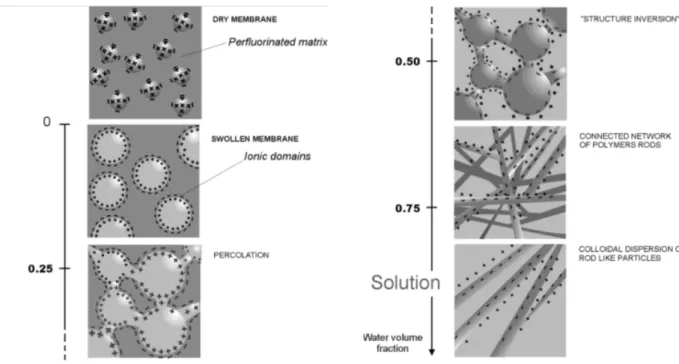
Among the different model, a plausible mechanism for the evolution in structure from the widely accepted concept of isolated clusters, for membranes containing relatively low water contents, to rod-like structures in solution, was offered by Gebel, and is shown schematically in Figure 17[44]. According to this qualitative model, the dry membrane is considered to contain isolated, spherical ionic clusters with diameters of ~1.5 nm and a center-to-center separation distance of ~2.7 nm. The absorption of water induces a progressive clusters swelling until the membrane “dissolves” into solution. The rodlike structures separate to yield a colloidal dispersion of isolated rods: the structure of highly swollen membranes is very close to that of the Nafion solution.
Figure 17. Conceptual model fot the morphological reorganization and continuity of the ionic
domains in Nafion as the dry membrane is swollen with water.
One of the latest models for Nafion morphology has been proposed in 2007 by Schmidt-Rohr and Chen[45]. The application of a recently introduced algorithm to the small-angle scattering data present in litterature allowed them to propose a water-channel model for Nafion structure. According to this model, the structure of Nafion at a hydration level of 20 vol% (11 wt% ) water, is made up of water channels (cylinders), whose diameter ranges between 1.8 and 3.5 nm, with an average of ~ 2.4 nm, lined with hydrophilic side groups, Fig. 18a,b. Such channels, that are locally parallel to their neighbours and can be considered as cylindrical inverted micelles, are stabilized on the outside by the relatively straight helical backbone segments. The stiffness of the helical backbone segments[46, 47], can stabilize the long cylindrical structures. The water-channel model naturally accounts for many of the outstanding properties of Nafion, in particular its high proton conductivity and water permeability[48] as well as the large permeation, diffusion coefficient and electro-osmotic drag[49].
Currently, this simple water-channel model seems to provide a unified view of the structure of Nafion.
Figure 18. Parallel water-channel (Inverted micelle cylinder) model of Nafion. a, Two views of
an inverted-micelle cylinder, with the polymer backbones on the outside and the ionic side groups lining the water channel. Shading is used to distinguish chains in front and in the back.
b, Schematic diagram of the approximately hexagonal packing of several inverted-micelle
cylinders. c, Cross-sections through the cylindrical water channels (white) and the Nafion crystallites (black) in the non-crystalline Nafion matrix (dark grey), as used in the simulation of the small-angle scattering curves.
As we have just seen, these models have led to a much clearer understanding about morphology and transport features of ionic domains in Nafion. In contrast, the nature of the crystalline component has received little attention: the relevance of this morphological feature to the technologically important properties of the membranes is still unclear. However, since the initial studies on Nafion morphology, the crystalline component has been recognized as an important structural feature and often considered as a necessary component that provides mechanical integrity and a barrier to solvent swelling: it is crucial for mechanical properties, acting as physical crosslinks[50]. Therefore, acting on the crystalline part of the polymer, for example by redissolution in appropriate solvent[51], one can generate distinct ordered structures in the clusters and form a network between clusters using the short channels that connect the aggregates. Upon doing so, the original ionomer properties can be altered and tailored to specific uses and needs, such as, specific gas and liquid separations and fuel cell operations.
Two main research areas currently of interest on Nafion® are the transport phenomena within the membrane and in particular modifications made to the membrane to increase its performance as well as water retention capacity. PFSA-based fuel cell technology, in fact, still suffers of several shortcomings, primarily due to the use of Nafion membranes:
the high cost of membrane amounting to US$ 700 per square meter[52]; lack of safety during its manufacture and use[53];
requirement of supporting equipment[54], e.g. the hydration system adds considerable cost and complexity to the vehicle;
temperature related limitations[55]; methanol crossower[56].
Despite its shortcomings, Nafion® is still the polymer of choice for most PEFC and DMFC applications. However, it is likely that Nafion® will be replaced by an alternative membrane in the future[57]. To overcome few of the disadvantages enumerated above, the researchers are carrying out an intensive research work to identify promising alternatives[58]. Rikukawa and Sanui[55] suggest that in order to produce materials that are less expensive than Nafion, some sacrifice in material lifetime and mechanical properties may be acceptable, provided the cost factors are commercially realistic. Hence, the use of hydrocarbon polymers, even though they had been previously abandoned due to low ionic conductivity, has attracted renewed interest[34].
Non‐fluorinated hydrocarbon polymers
Promising candidates for proton exchange membrane synthesis are non-fluorinated hydrocarbon polymers. These can be aliphatic or aromatic polymers bringing benzene ring structures in the polymeric backbone of membrane or in the bulky pendant groups from this membrane polymeric backbone. Presently, one of the most promising routes to high-performance proton conducting polymer electrolyte membranes is the use of hydrocarbon polymers for polymer backbones[59]. Hydrocarbon membranes provide some definite advantages over perfluorinated membranes: from one side they can be synthesized with relatively inexpensive and commercially available