U
NIVERSITÀ DELLA
C
ALABRIA
Dipartimento di Elettronica,
Informatica e Sistemistica
Dottorato di Ricerca in
Ingegneria dei Sistemi e Informatica
XXIII
Tesi di Dottorato
QoS Aware Multicast Routing and
Meta-Heuristics over Multi-Layered Satellite-Hap
Networks
DEIS- DIPARTIMENTO DI ELETTRONICA,INFORMATICA E SISTEMISTICA
Novembre
To My Love Darina
To My Princess Daniela
To My Hurricane Matteo
Acknowledgements
I would like to give many many thanks to all people that help me in these last years, which are spent for research and dreams. Working with the people of the Telecom Lab has been wonderful. All time passed in laboratory has been richer of funny moments and hard work that has permitted me to growth professionally and as man. Many thanks to Floriano and Mauro, which are for me two awesome people and they have demonstrate to be Friends.
Many thanks to Prof. Salvatore Marano because he trusted me every mo-ments also in these last few years when I have to go.
I would like to spent some words for my family, which is composed by super peoples that have demonstrate a great love for me and for my family too. They have been a reference point during all my life. I’m very proud of each one of them, starting from my father Giuseppe called by me jurassic man because he hates all new things; my mother Eleonora that is a very Mom and for me represents a reason to do better every day; my sister Sabrina that is a hard head and she doesn’t hear me on everything also when she fall in faults, but for this reason I love she; my Sister Manuela that when she was young was much more similar to me than now, but she is growth, maybe in better, of course :).
My uncle Franco called with the oldest name of zio Black, is for me one of the most important people of my life. He is a light and I see in him everything of good that exist in the world. The best one.
My uncle Silvio, which is totally different from zio black, but he is a refer-ence point for me and for my family too. He is present ever without condition, I totally admire hime for those he made in his life. He is fall but he is rise with his force only.
My aunt Alba, she had help me in hard moment and she is always available for any reasons.
My Grandfather and Grandmother Amilcare and Nonna Barone, there aren’t words enough to dedicate them. They are good people that have been demonstrate their love towards me and my family every time I need an help or simply a confortant word. I love them for those they made for me.
iv
My Grandmother Carmela she is a sweet people and they lives her life in a hard manner and I know she miss my Grandfather Pietro. She is a great nonna for all she made for me when I was young and for those she made when I married.
Pietro for me is all, a guide, a great man that I love previously, now and further. I never forget him and only a word, Nonno I miss you. Help me every time.
A great hug to my parents in law Alla and Valerio because they have been with us every moments and in particular in hard moment of our life. They want al lot of love to their daughter Darina and I know how much is hard for them to have their daughter so far from them. Thanks to trust into me and Thanks to give us your support.
A special thanks to my Friends Fiore and Maria that being to be a new family, I hope for them many many years of Happiness and Love.
Emilio, we are friends from long years and you have demonstrate to be a friend on which I can trust.
Fabio, I’m not forget about you and your family. You was and you are my best friend. Thanks to you my life was better and I’m proud to be your friends. I hope that you and your wife Dorota can be happy with your daughter Laura. And now, at the end but only because they are the most important people that I have, my Family. I start to spent some words about Matteo, last that are coming into my life, but he fulfill my life with his fun and hurricane moments that brake the monotony of the day and make every day different from other ones, I love you because when I look into your eyes I see me and Mommy at same moment. Then my princess the best daughter ever, you are the light of my life, and you are come to make me and your mommy happy and proud of you. You are so sweet and beautiful that does not exist words to describe you. I love you.
At the and you, my Love, Dascha, sometime you are angry and your voice tone is a little bit higher than the normal, but I love you, because you are true and genuine, you do every things without ask for a thanks. I can give you only my Love and my life. You make feel me happy and good every time. You are a friend, a perfect Mother, but you are also the most beautiful woman in the world.
Thanks to everyone that know me, because You have make this true. This is a dream that are come true. Thanks to God for all of about this.
Summary
In the last few years, multimedia broadband services and applications are growth. More resources have been requested to the networks and more Qual-ity have to be supplied for the services. Moreover, new kind of networks were born such as wireless network and cellular networks such as 3G/4G and UMTS, also wired connections are evolved and more resources are available to allow new services and applications.
In these years, social networks and multimedia applications are increase ex-ponentially making possible new field of applications. With new technologies, in fact, it is possible to supply utility services such as tele-health, wireless health monitoring, public safety services and much more services over the internet, WAN and so on.
Moreover, dedicated services and networks can be rapidly installed in case of emergency scenarios such as war or natural disaster cases.
For these reasons, new network architectures can be implemented to offer a wide range of services. In particular, it is thinkable to interoperate between different network such as Satellite network, Cellular network and Wired Net-work to take advantages from all netNet-works reducing weakness. Moreover, it is necessary to increase resources availability making efficient choices and optimizing reservation along links on which network data flows.
To make these scenarios possible services and network have to offer a rea-sonable Quality in terms of Quality of Service (QoS). To do this new protocols and algorithms capable to take advantages from modern network infrastruc-tures have to be designed. A wide range of services can be distributed on the network in a multicast manner, for example multimedia data such as video and audio can take advantages from multicast transmission reducing in a drastic manner the number of control packets and data packets sent into the network. In case of unicast transmission, in fact, a higher number of packets than the multicast are sent into the network to allow each destinations to receive data flows.
In order to make more robust, reliable and scalable multicasting on the hybrid network, a multicast algorithm has been associated to the the
vi Summary
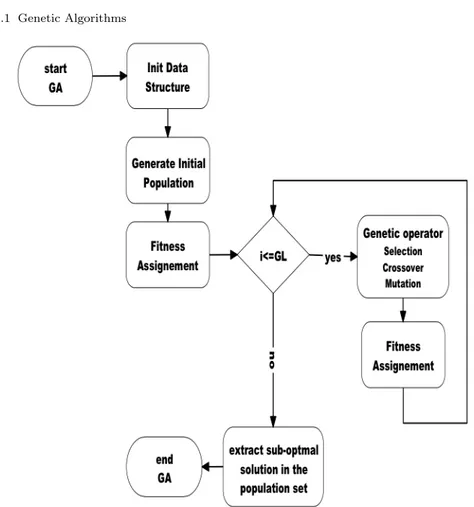
ticast protocol, when a multi-constraints QoS aware multicast have to be addressed. A multicast algorithm that has the main goal to find a multicast tree in an multi-constraints environment belongs to the NP-Complete class of problem. In literature this is known as a Steiner Tree Problem (STP). In order to solve this issue a new class of algorithms has to be addressed. In particular, taking into account limited resources of the routers and time limits a heuristic method has to be designed. In these last years a series of algorithms that derive by the observation of natural evolution and biological process that are also called biologic algorithms, pay out much attention. In this works, the Genetic Algorithm (GA) adapted to Multicast issues has been designed and proposed to provide a better resource management that allow a higher number of multicast sessions and higher number of users to join into the network. This allows a network cost reduction and offers better services with a higher quality to the community.
To spread services around wide areas with same quality, a broadband network, which are not sensible to terrestrial overloaded network, have to be addressed to distribute with reliability and scalability multicast services. Satellite network equipped with newest architecture such as DVB-RCS or DVB-S2 that implements two way services represents an optimal solution to distribute broadband services, because it also support a certain realtime in-teraction between sources and destinations without changing of network. This architecture has the main problem to have a higher round trip delay owing to the distance between satellite and Earth surface, in fact, some applications such as realtime applications do not support satellite communications. For these reasons, and in general to reduce, where possible, round trip delay an intermediate network has been introduced into infrastructure. HAPs meshes are composed of several on air platform that provide wireless broadband com-munications. They can interact with cellular platforms or with most common wireless networks changing their payload if necessary. An interaction of Satel-lite and HAP can reduce delays and increase network performances. In order to make this possible an efficient multicast protocol capable to address in an efficient manner data flow and protocols interaction between several entities has been designed and proposed. Moreover, using aforementioned algorithm, efficient routing has been addressed. In this hybrid network, which is based on a DVB-RCS like architecture, local communication can be made exploit-ing HAPs or wired network. instead, in case of far connections satellite link can be used as bridge among HAPs network, otherwise satellite can be used directly to connect a terrestrial router with another one when HAPs links are overloaded or in case of some areas where HAP coverage is not present.
Contents
Summary . . . v
List of Figures . . . xii
List of Tables . . . xiii
Acronyms . . . xv
1 Satellite and Hap multimedia Network . . . 1
1.1 Satellite Network . . . 1
1.1.1 How satellite network works . . . 2
1.1.2 Satellite Type . . . 3 1.1.3 DVB-RCS . . . 4 1.1.3.1 DVB-RCS Architecture . . . 5 1.2 HAPs mesh . . . 7 1.2.1 HAPs types . . . 9 1.2.1.1 Aerostatics Balloon . . . 9 1.2.1.2 Airplane . . . 9
1.2.1.3 Unmanned Aerial Vehicle (UAV). . . 9
1.2.2 HAPs Available Frequency . . . 10
1.2.3 HAP communications system advantages . . . 12
1.2.4 HAP communications system issues . . . 13
1.3 Heterogeneous Network . . . 14
1.4 Conclusions on Chapter 1 . . . 16
2 Qos multicast aware on multilayer hierarchical network . . . 19
2.1 Multicast Routing Overview . . . 19
2.1.1 Multicast Tree . . . 21
2.1.2 The life cycle of a multicast group . . . 22
2.1.2.1 Multicast Group(Session) Creation . . . 22
2.1.2.2 Multicast Tree Construction with Resource Reservation . . . 23
viii Contents
2.1.2.3 Data Transmission . . . 23
2.1.2.4 Group Teardown . . . 24
2.2 QoS Aware Multicasting . . . 24
2.2.1 Multicast Algorithms and Issues . . . 24
2.2.2 STP . . . 26
2.2.2.1 STP reduction . . . 27
2.3 Multicast Protocols . . . 28
2.3.1 Source Based (SB) Multicast Tree Protocols . . . 29
2.3.1.1 Distance Vector Multicast Routing Protocol (DVMRP) . . . 29
2.3.1.2 Multicast Open Short Path First (MOSPF) . . 29
2.3.1.3 Protocol Independent Multicast - Dense Mode (PIM-DM) . . . 30
2.3.2 Core Based (CB) Multicast Tree protocols . . . 30
2.3.2.1 Protocol Independent Multicast - Sparse Mode (PIM-SM) . . . 30
2.3.2.2 Core Based Tree (CBT) . . . 30
2.3.3 More on Multicast tree protocols . . . 31
2.3.3.1 Network State - Storing and Updating processes . . . 31
2.3.3.2 Tree Finding processes . . . 32
2.3.3.3 Tree management and assessment due to join/leave updating . . . 32
2.3.3.4 Tree state management . . . 33
2.3.3.5 Scalability . . . 33
2.4 Problem formulation . . . 33
2.4.1 Network Representation . . . 34
2.4.2 QoS Multicast Analytical Formulation . . . 34
2.4.3 QoS Multicast Constraints. . . 36
2.5 Conclusion on chapter 2 . . . 37
3 Metaheuristics algorithms for QoS optimization . . . 39
3.1 Genetic Algorithms . . . 39
3.1.1 Coding and Decoding of the Multicast Tree . . . 41
3.1.2 Starting Population . . . 43
3.1.3 Multicast tree reconstruction . . . 44
3.1.4 Fitness Assignment . . . 44
3.1.5 Genetic Operators . . . 46
3.1.5.1 Disconnected Tree Issue . . . 48
3.1.5.2 Convergence Issues . . . 48
3.1.5.3 Genetic Algorithm results . . . 49
3.2 Broadcast gain . . . 49
3.2.1 Hybrid Algorithm . . . 52
3.3 Simulated Annealing . . . 53
Contents ix
3.3.1.1 Algorithm coding . . . 55
3.3.1.2 Neighbors Generation . . . 58
3.3.1.3 New solution algorithm . . . 59
3.3.1.4 Inner Energy Function . . . 59
3.3.1.5 Temperature Function . . . 61
3.4 Multicast Algorithm Simulation Campaigns . . . 63
3.4.1 Multicast tree density coefficient . . . 64
3.4.2 Optimal Solution Degree distance . . . 65
3.4.3 GAAlgorithm results. . . 66
3.4.4 Hybrid Cost Delay Bandwidth - Genetic Algorithm (HCDB-GA) versus Simulated Annealing (SA) Simulation Campaigns . . . 70
3.5 Conclusions on Chapter 3 . . . 74
4 QoS multicast protocol and algorithm . . . 77
4.1 Reference Scenario . . . 78
4.2 Multicast Protocol . . . 78
4.2.1 Join Multicast session . . . 79
4.2.2 Multicast Tree Maintenance . . . 81
4.2.3 Member Leave . . . 81
4.2.4 End Multicast Session . . . 82
4.2.5 QoS Aware multicast protocol . . . 82
4.2.6 Core Election . . . 85
4.3 Multicast Protocol and Multicast Algorithm integration . . . 86
4.3.1 CBT with QoS aware support . . . 87
4.3.2 Enhanced - Core Based Tree (E-CBT) QoS Aware Multicast Protocol. . . 89 4.4 Simulation campaigns . . . 91 4.5 Conclusion on chapter 4 . . . 95 Conclusions . . . 97 References . . . 101 List of Publications . . . 105
List of Figures
1.1 Satellite Network Architecture . . . 2
1.2 DVB-RCS Architecture . . . 6
1.3 HAPs mesh Architecture . . . 8
1.4 Aerostatics Balloon . . . 9
1.5 Airplane HAP . . . 10
1.6 UAV - HAP . . . 10
1.7 HAP available Frequencies . . . 11
1.8 Rain Effects on Signals . . . 11
1.9 Scattering Effect on Signals . . . 12
1.10 Multilayer Architecture . . . 15
2.1 Network Topology views as a Graph . . . 35
2.2 Multicast Tree achieved from Network Topology . . . 35
3.1 Genetic Algorithm Flow Chart . . . 41
3.2 SA Binary code . . . 56
3.3 SA Path coding . . . 56
3.4 SA coding proposal . . . 57
3.5 Solution with loop, which is not allowed . . . 57
3.6 not allowed solution due to node presence into solution . . . 57
3.7 Neighbor Generation Process . . . 58
3.8 Common Temperature Trend . . . 62
3.9 Proposed Temperature law trend . . . 63
3.10 Average End-to-End Delay vs. Generations . . . 66
3.11 Average available bandwidth vs. Generations . . . 67
3.12 Algorithms solution density chart. . . 67
3.13 End-to-End delay vs. h1,h2 coefficients variation . . . 68
3.14 Available Bandwidth vs. h1 and h2 coefficients variation . . . 69
3.15 Density chart vs. h1 and h2 coefficients variation . . . 69
3.16 CCDB-GA vs MOGA in terms of execution time . . . 69 3.17 CCDB-GA vs. MOGA - End-To-End Delay at iterations steps 70
xii List of Figures
3.18 CCDB-GA vs. MOGA - Cost trend comparison at iterations
steps . . . 71
3.19 Execution time comparison between GA and SA algorithm . . . 71
3.20 Average End-to-End delay found by algorithms . . . 72
3.21 Minimum Available bandwidth along the paths between source and destinations . . . 72
3.22 Average End-to-End delay vs. Multicast group increasing . . . 73
3.23 Max End-to-End delay trend vs. Multicast group increasing . . 73
3.24 Distance among the optimal solution and meta-heuristics found solution . . . 74
4.1 Multicast Protocol Reference Network and Join Message scenario . . . 79
4.2 Join Request Message . . . 80
4.3 Join Acknowledgment (ACK) Message . . . 80
4.4 EMS . . . 83
4.5 Terminals Answer to EMS . . . 83
4.6 E-CBT example working scenario . . . 87
4.7 QoS aware CBT . . . 88
4.8 E-CBT main Loop . . . 89
4.9 E-CBT Algorithm Trigger . . . 90
4.10 Packets number vs. source generation probability . . . 91
4.11 Protocols packets number vs. source generation probability . . . 92
4.12 RCST link average utilization vs. source generation probability 93 4.13 HAP link average utilization vs. source generation probability . 93 4.14 Average HAP layer Links Utilization . . . 94
4.15 Average RCST layer Links Utilization . . . 94
List of Tables
1.1 User Account and Available Time Slots . . . 4 1.2 Coverage areas of the HAP based on elevation angle . . . 9
Acronyms
ACM Adaptive Coding and Modulation ACK Acknowledgment
BER Bit Error Rate BG Broadcast Gain
BSMA Bounded Shortest Multicast Algorithm CB Core Based
CBT Core Based Tree
CCDB-GA Constraints Cost Delay Bandwidth - Genetic Algorithm COLM Constrained Online Multicast
CPU Control Processor Unit DVB Digital Video Broadcasting
DVB-RCS Digital Video Broadcasting with Return Channel Satellite DVB-H Digital Video Broadcasting for handheld terminal
DVB-S2 Digital Video Broadcasting - Satellite two DiffServ Differentiated Services
DVMRP Distance Vector Multicast Routing Protocol EMS End Multicast Session Message
FWL Forward Link
E-CBT Enhanced - Core Based Tree EMS End Multicast Session
ETSI European Telecommunications Standards Institute GA Genetic Algorithm
GEO Geostationary Satellite HAP High Altitude Platform
HCDB-GA Hybrid Cost Delay Bandwidth - Genetic Algorithm HEO High Earth Orbit
IGMP Internet Group Management Protocol IntServ Integrated Services
ITU Internation Telecommunication Union LDMS Local Multipoint Distribution Services LEO Low Earth Orbit
xvi Acronyms
LSA Link State Advertisement
MF-TDMA Multi Frequency - Time Division Multiple Access MODCOD Modulation and Coding
MOGA Multi Objective Genetic Algorithm MOSPF Multicast Open Short Path First MPE Multi Protocol Encapsulation MTDC Multicast Tree Density Coefficient NCC Network Control Center
NCR Network Clock Reference OBP On Board Processor
OSC Optimal Solution Coefficient OSPF Open Short Path First
PIM-DM Protocol Independent Multicast - Dense Mode PIM-SM Protocol Independent Multicast - Sparse Mode QoS Quality of Service
RCST Return Channel Satellite Terminal RIP Routing Internet Protocol
RP Rendezvous Point RPM Reverse Path Multicast
RSVP Resource Reservation Protocol RX Receiver
SA Simulated Annealing
SAMRA Simulated Annealing Multicast Routing Algorithm SB Source Based
STP Steiner Tree Problem TSA Tabu Search Approach TX Transmission
Chapter 1
Satellite and Hap multimedia Network
In this chapter the reference network is described in details. As known, nowa-days, more resources and more amount of contemporary connections are re-quired in order to satisfy population services requirements. Moreover, the growth of service complexity and increasing of requested quality require a bet-ter resource management to be performed. In order to satisfy all requirements a multilayer architecture with a hierarchal organization has been addressed in this work[12]. This network is composed of a satellite layer based on Digi-tal Video Broadcasting with Return Channel Satellite (DVB-RCS) standard that is connected with a High Altitude Platform (HAP) layer which could be organized into more HAPs mesh. This kind of network can floods several type of applications, moreover several fields of employment can be found.
This architecture is easy to configure and it offers robust communica-tions and wide coverage areas. Furthermore, it can be used to solve last mile problem also in those areas where broadband communications are not available due to limitations of wired infrastructure. Multi Protocol Encap-sulation (MPE), which is supplied with the DVB-RCS architecture, allow users to connect with the external TCP/IP networks offering a wide range of services and applications.
1.1 Satellite Network
DVB-RCS and current DVB-S2 satellite networks permit to send and receive data on uplink and downlink connection with high bandwidth. This per-mits several services to be distributed on this networks that previously were not allowed due to the architectural limits of the oldest satellite networks. Previously satellite networks allowed only one-way services to be addressed, because first generation of satellite was designed to only sent broadcast data that does not need an interactive modality. Satellite network is composed on a Satellite equipped with an On Board Processor (OBP), which
2 1 Satellite and Hap multimedia Network
cates with several Return Channel Satellite Terminal (RCST). RCSTs allow end users to connect to the network, each RCSTs allow at max 16 terminals at the same time to be connected[25, 43, 42].
Satellite network, as known, offer high broadband wireless connections and wide footprint, but suffers by a higher round trip delay due to the dis-tance between terminals and satellite. The DVB-RCS allow to interoperate with TCP/IP based network thanks to the Gateway (GTW) that supplies a redesigned TCP/IP protocol[18, 44, 45].
1.1.1 How satellite network works
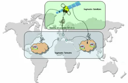
The satellite network is composed of an OBP satellite node that communi-cates with several RCSTs in different areas. Each area is covered by a spot of the satellite that is also called spot footprint. The satellite network is also divided into two sections that are: space segment and the terrestrial segment as shown in Figure 1.1. The Space Segment is composed of the satellite and the Master and Control station, instead the Terrestrial Segment is composed of RCSTs nodes and gateway.
Fig. 1.1 Satellite Network Architecture
Satellite offers wide areas coverage and allows user to avoid territorial limit on quality of the communications, these limits are represented by national rules and laws. Moreover, robust and feasible communications are available, but several limits such as one-way communications, high complexity of
ter-1.1 Satellite Network 3
minals and the high cost of the devices make this architecture hard to spread and acquire wide slice of market [31, 32, 42].
1.1.2 Satellite Type
Several type of satellite networks exist, each type of satellite network of-fer different performances. Most common satellite type is the Geostationary satellite system where the satellite is located in an orbit around 36000Km far from the earth surface.
Orbit is the trajectory that a satellite describes during its travel around the earth. Satellite trajectory is designed to avoid that the satellite goes into gravity field falling to the earth. The trajectory minimize the force needed to balance the attraction force generated by the gravity. Orbits depends of satel-lite distance and inclination respect the earth equatorial plane or inclination respect earth axis. Most common orbits are:
• Elliptic Inclined Orbit : in this case the orbit is inclined respect the equa-torial plane with an inclination angle of 64 degree. This orbit is stable and it is designed to balance the gravitational force, moreover it is well suitable for mobile communications because it solves problem related to natural or artificial obstacles. This orbit is used to supply services at high latitude such as earth poles.
• Circular inclination Orbit : Altitude of the satellite is constant, its incli-nation is around 90 degrees and it is particular suitable to cover all region of the earth.
• Circular Orbit with null inclination : This orbit presents an inclination angle of 0 degrees on the equatorial plane. Geostationary orbit is the most popular and known orbit. The satellite has an altitude that is constant. the satellite period time is the same of the earth, and for this reason the satellite seems to be a fixed point in the sky. This kind of orbit guarantees a coverage time of 24h per days and a greater footprint, in fact Three satellite are enough to cover all earth surface. This kind of satellite does not permits to cover polar area or high latitude.
Satellite systems like Geostationary Satellite (GEO) are easy to configure in terms of terrestrial and space segment and offer wide footprint, but they present a high round trip delay and the lower inclination angle does not permit to cover high latitude. Low Earth Orbit (LEO) systems offer lower round trip delay than GEO satellite and it is possible to use little terminals to receive signal. Therefore, handheld service can be supplied with this kind of satellite system, moreover the receiver chain is not complex and this permits a reduction of the terminal cost. LEO systems are lesser visible than the GEO and a constellation of satellite is needed to have a good footprint. Moreover, the satellite payload is more complex and a more complex protocols
4 1 Satellite and Hap multimedia Network
are needed to manage more frequent handovers. High Earth Orbit (HEO) satellite are much similar to a GEO satellite rather than the LEO satellite, therefore, we found high round trip delay and packet loss due to the altitude and environment condition, but taking into account their inclination angle these satellite make possible the coverage of high latitude.
1.1.3 DVB-RCS
The DVB-RCS standard is proposed by the European Telecommunications Standards Institute (ETSI) and its supply rules to be respected by the satel-lite architecture in order to distribute services and applications over the net-work. It is composed by a satellite, often equipped with OBP which has the capability to regenerate network flow cleaning it by the channel noise and increasing communications quality. Moreover, thanks to the MPE it is also possible to introduce into MPEG-2 Streaming TCP/IP packets[44]. This allows system to operate with multimedia Broadcasting services and internet-working services and applications.
DVB-RCS allows users to send packets in a two way manner, thus means that it is possible to send and receive contemporary using the satellite net-work. Moreover, high bandwidth is offer both in uplink and downlink seg-ment. In fact in uplink the available bandwidth is up to 2 MBps while for the downlink it is possible to reach the 56 MBps[2].
End-user terminal transmits using a scheduled hub with a burst schema based on Multi Frequency - Time Division Multiple Access (MF-TDMA), this allows to achieve a slot temporal division of the transmission, but for each slot it is possible to send several services using several carriers. The forward link is the logical link that connects the HUB with the Terminals and merge video broadcasting with data flow of the TCP/IP layer. This link is based on the DVB standard that can use ATM or IP encapsulating this data into MPEG-2 TS. Forward link is used by the satellite only in order to transmit data in a broadcasting manner. Return channel is shared between the RCSTs that send data towards satellite and Gateway if data have to go outside the DVB-RCS network. Slots have assigned to the RCSTs taking into account user typology. In fact based on the user account the RCSTs can addressed a certain number of slots.
User Account Available Bandwidth Time Slots Carrier
144 Kbps 60 10
384 Kbps 23 26
1024 Kbps 9 28
Corporate 2 MBps 4 136
1.1 Satellite Network 5
1.1.3.1 DVB-RCS Architecture
The DVB-RCS standard provides to supply how DVB-RCS works. In partic-ular, it supplies all information about each component of the system such as Satellite, RCSTs NCC, HUB and how signals have to be managed starting from coding, modulation signal power and so on. Moreover, log-in procedure, synchronization, TX and Rx parameters information are also given. System is composed of a Satellite that receives traffic from the RCSTs, Network Control Center (NCC) and HUB and distribute data among them. The NCC is an en-tity that manages sessions and supplies sinchro and transmission information to RCSTs. HUB has the main task to allow communication between DVB-RCS network and external network. Other details about network components are herein given.
The NCC has the main task to control and manage the network composed by satellite, RCSTs, feeder and gateway. The two way architecture has in-troduced several problem and the complexity of the system is increased, for these reasons the NCC uses more resources to make all tasks. NCC manages the network accesses and in particular the log-on procedures that each RC-STs have to perform in order to receive network services. In fact, to allow a RCSTs to log into the network the NCC has to send the Forward Link (FWL) information and the clock synchro (Network Clock Reference (NCR)). Once the NCR is set and the log-on procedures is successfully end, the NCC sends towards the RCST all information about the network and transmission con-figuration. The NCC has the possibility to disconnect a RCST and change transmission parameters if something change during the session.
The HUB is a key element of the DVB-RCS architecture, it supplies con-nection between terminals and external network allowing internet-working. In particular it supplies the following services
• Manage traffic coming from the internal terminals that uses the Return Channel of the satellite network;
• Manage accounting services to supply interactive services and connection with external public network;
• Allow connections with external server provider, DB and multimedia ser-vices also in pay per view;
• Allow connections from external traffic towards internal devices using MPE to exploit the DVB forward link to reach devices;
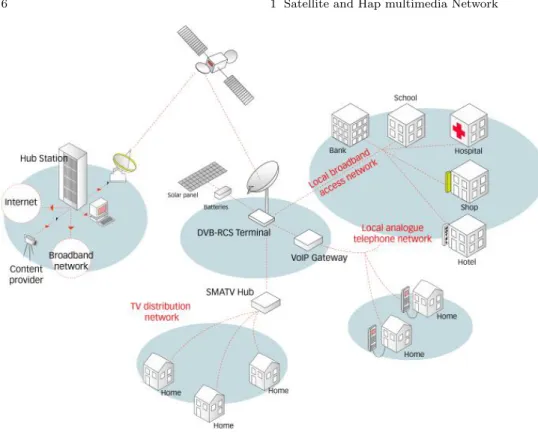
The RCSTs are used by the users to achieve access at the network, Using the RCSTs it’s possible to receive services by the interactive network and com-municate with other devices that belong to the network and other user that are external at the network but connected to internet. In case OBP satellite RCSTs can communicate among them directly saving time and increasing robustness of the system. The RCTs allow user to exploit the return channel of the network.
6 1 Satellite and Hap multimedia Network
Fig. 1.2 DVB-RCS Architecture
In these last few years several updates have done to the DVB-RCS stan-dard and in particular DVB-RCS+M and DVB-RCS2 stanstan-dards have been presented. The DVB-RCS+M is even a DVB-RCS platform that supports Digital Video Broadcasting - Satellite two (DVB-S2) standard that allows us to achieve enormous advantages such as more robust transmission and re-duction of packet loss, moreover a better QoS is supplied taking into account the capability of the new standard to better manage class of traffic thanks to new packet scheduling on satellite payload. Moreover, the capability of the RCSTs to change the Transmission (TX) parameters taking into account environments conditions guarantees that the transmission better adapt to external conditions such as climate and overload of the network.
On the other hand, the new generation of satellite networks (DVB-S2 standard) are based on interactive and adaptive bidirectional links, allowing a data rate up to 2Mbps for each user in return link, that provides better perfor-mance and robustness respect the previous standard. DVB-S2 was developed around three key concepts: best transmission performance, total flexibility and reasonable receiver complexity. These goals are also obtained through the Adaptive Coding and Modulation (ACM) for the forward link: in fact, DVB-S2 can perform several kinds of Modulation and Coding (MODCOD)
1.2 HAPs mesh 7
allowing to achieve a wide range of configurations and a very flexible sys-tem capable to adapt itself to the channel variations[54, 19, 14, 7]. Nowadays DVB-S2 is widely investigated owing to its capability to outperforms other similar technologies. DVB-S2 standard permits to distribute several types of services with a certain Quality of Service (QoS). ACM technique permits to adapt satellite FWL to Channel condition respecting the QoS requirements. A suitable resource management is a key factor because it can enhance the overall system performance exploiting the ACM technology. Moreover, ACM permits to give the possibility to adapt the system to the user preference and application requirements. Thus, it permits to obtain a more flexible system. Therefore, it is very important the communication from Satellite terrestrial Terminal to Satellite. In fact, Satellite Terminals send feedback messages to-wards Satellite, which contains information about the quality of the received signal.
1.2 HAPs mesh
HAP covers wide areas with a high bandwidth both in uplink and downlink, moreover an inter-hap communication is allowed. Using HAP it’s possible to cover several areas such as urban, sub-urban, rural and disadvantaged areas. HAPs are easy to configure and new networks can be installed without terminal configurations, if terminals are just configured. This make possible to install new networks avoiding time wasting. Moreover, HAPs can be installed using light airplane, air static ballon or most recent UAV, where human pilots are not needed, this permits to save time and reduce risks for human life. Useful working time is increased and only maintenance and autonomy issues can force terminals landings. This terminals present a leak side related to their autonomy[30].
Each HAP can communicate with other one exploiting inter-hap link and high bandwidth is guaranteed. HAPs are organized into several groups where each group being to be a mesh. However, HAPs solve several issues and well fit those problems related to crisis scenarios such as post natural disaster or war environments. Several kind of applications can be distributed such as videoconference, tele health, resource sharing, private communications and multimedia services. Moreover, HAPs can be used to distribute cellular ser-vices such as 3G cellular and Digital Video Broadcasting for handheld termi-nal (DVB-H) networks allowing handheld communications to be addressed (see Figure1.1.3.1).
HAP system represents a valid support to other technologies that actually are supplied, in other words terrestrial and satellite infrastructures. HAP supplies connection for several kind of terminals, which can be fixed or mobile or handheld. A commonly supported bit rate per link is around 20 Mb/s, this bit rate can be reached with a limited antenna[34].
8 1 Satellite and Hap multimedia Network
Fig. 1.3 HAPs mesh Architecture
HAPs allow users to communicate with high bandwidth and lower propaga-tion delay. For these reasons this architecture has been chosen to interoperate with DVB-RCS networks. HAPs can be used to serve local area exploiting low propagation delay and high bandwidth. In order to communicate with far location the OBP satellite is also used. Moreover, taking advantage from the high bandwidth is also possible to offer the same class of services and applications of the satellite layer without loss of QoS.
HAPs are installed around 17-21 Km because in these atmospheric altitude no strong winds or turbulence are present. This choice is made due to stability issues of the HAP in order to allow stable connections and reduce unlike effects. Given an altitude and an elevation angle (g) it is possible to find the coverage area using the following formula
d = 2R⇤ arccos R R + h⇤ cos(g) ! g ! (1.1) where R is earth range and h is the HAP altitude. For the elevation angle has been defined a lower bound that it’s 5°. Each coverage area is subdivided in cells to increase coverage are exploiting the frequency reuse technique. In order to avoid area with too load the most useful elevation angle is chosen to be 15°.
Based on previously formula it is possible to identify coverage area having as key factor the elevation angle
1.2 HAPs mesh 9 Area Name and Description Elevation Angle Range
Urban Area Coverage [30°, 90°]
Sub Urban Area Coverage [15°, 30°]
Rural Area Coverage [5°, 15°]
Table 1.2 Coverage areas of the HAP based on elevation angle
1.2.1 HAPs types
the HAP are suitable to offer a wide range of services and applications, more-over due to the wide range of services that they can supply several payload types have been developed. For these reasons several kinds of HAPs have been designed. Most common vehicles are aerostatics ballon, UAV and airplane 1.2.1.1 Aerostatics Balloon
This type of HAP is essentially 150 mt. length. Their position in air is main-tained using electrical engines that exploit solar panel to exploit solar energy. These panels are positioned at the external of the balloon.
Fig. 1.4 Aerostatics Balloon
1.2.1.2 Airplane
The airplane HAP are maintained in air for 8 hours, they are driven by a pilot and a copilot and a 24 hours a day service coverage is always guaranteed. Support airplane is sent in prefixed time slot to allow airplane turnover. Once they are active they make a circle to supply service at 22 Km of height. 1.2.1.3 UAV
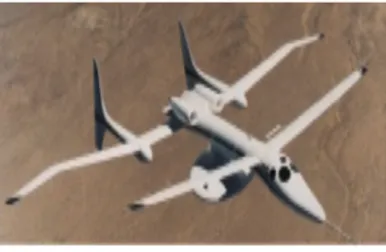
This kind of vehicles represents a valid alternative to the previously systems. They are acquiring several market because they are pilot free and they land
10 1 Satellite and Hap multimedia Network
Fig. 1.5 Airplane HAP
only for maintenance and refueling issues. Since they are ultra-light systems a little fuel tanks is present, for this reason they can be sent on air only for a limited time.
Fig. 1.6 UAV - HAP
1.2.2 HAPs Available Frequency
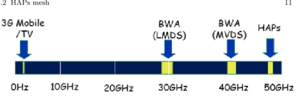
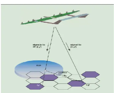
The range of used frequencies is wide due to the nature of the HAPs that al-low several kind of communications. The dedicated bandwidth are 122 band of 300Mhz each one around 47-48 GHz. For the wireless access with Lo-cal Multipoint Distribution Services (LDMS) are commonly used microwave frequencies across the 26 GHz and 29 GHz bands. For the broadcast commu-nications a bandwidth around 29.1-29.25 GHz is used while for the Mobile operator (3G network) it’s possible to use the bandwidth around 900-1800 MHz for GSM and 1885 and 2200 MHz for the UMTS. Moreover, HAP can be also used to distribute applications using the WiMax standard and the used band are typically 2.3 GHz, 2.5 GHz and 3.5 GHz (see figure1.2.2).
HAP offers many advantages but also presents several issues. Propagation is limited by the diffraction due to the high frequencies, which are used by the HAPs. This represents a limit for communication and also in terms of QoS, in particular for those metrics related to the packet loss ratio. In the HAP networking some transmission issues are present and hard to be faced, these are herein described :
1.2 HAPs mesh 11
Fig. 1.7 HAP available Frequencies
Distance Far is the distance and high is the packet loss ratio, often the distance factor to being considered is quadratic D2, in case of
cellular transmission the factor is D4.
Rain In case of rain some issues can be raise, in particular when a frequency around the 48 GHz and higher are used. In case of frequency up to 28 GHz rain effects could be not considered. The effects influence the power of the signals, in this way packet loss increase ( see Figure 1.2.2).
Clouds In this case the power loss depends of the used frequency and increase with the increasing of the frequency. In the LMDS band the dB loss are 0.1, 0.5 and 0.9
Scattering Is the radiation loss due to water particle that the signal meet during the travel, in this case the radiation are spread along the cells that use the same frequencies.
12 1 Satellite and Hap multimedia Network
Fig. 1.9 Scattering Effect on Signals
One of the main issue of the HAP is the positioning of the platform and the maintaining of the stability. It is important that these two parameters have to be respected because in case of loss of stability the overall quality and performances of the system is wasted. The Internation Telecommunica-tion Union (ITU) has designed that the platform has to be localized into a sphere of 500 mt. of radius. The maintaining of the position and stability represents a great issue for these vehicles, main problems are strictly related to stratospheric winds and turbulence. Winds and Turbulence might causes some problems that are more visible on light weight vehicles, instead greater vehicles are more stable and offer better performances. In order to solve this kind of problem it is possible to equip vehicles with antennas array that can change its position, antennas are designed to follow position and stability of the vehicle. Otherwise, it is possible to equip vehicle with mechanical hard-ware capable to correct position and stability. These solutions are possible but are very expansive in terms of cost.
1.2.3 HAP communications system advantages
In this section the possible advantages of the HAP communications are treated. HAP allows communication in a widely area due to their capability to cover wider area than a terrestrial system infrastructure. Moreover,
ter-1.2 HAPs mesh 13
restrial infrastructures need a greater amount of economic resources to be placed and a greater Natural impact than the HAP system.
HAPs offer a good flexibility to the traffic load due to their capacity to reuse frequencies and cells rearrangement. Moreover, HAP can be placed in different location in a easy way and with low cost. The HAP network is scalable respect the network size and load, in fact if more resources are needed other HAP can be connected to others exploiting inter - hap links, which offer a broadband connections allowing communications between HAP and HAP.
One of the key factor of the HAP system is that a complete system can be installed in a short time. In opposite condition, when the HAP system has to be installed also a short time is needed to perform this procedure, this allow us to save a lot of time and resources. Therefore, HAP can be rapidly used and they can be used in those scenarios where an emergency has to be treated shorter.
The mean time of life of a HAP is around 5 years, but sometimes a HAP can land due to payload updating or maintenance issues. Moreover, HAP is energy safe, solar energy is used to supply energy at whole system and they are impact free.
1.2.4 HAP communications system issues
The main issues of a HAP network are herein described, since the system was operative the ITU has assigned to the HAP high frequencies, which are around 47-48 GHz. At these frequencies the rain effects and the scattering effects are not treasurable but a more efficient transmission schema has to be used to supply services with a certain quality, in particular frequencies reuse has to be designed with more attention. To use network in a better way, a more efficient coding and modulation schemas have to be used in a broadband context. Moreover, QoS parameters such as the Bit Error Rate (BER) have to be considered.
Resources allocation and network protocols are under develop because a HAP system is different from other systems such as satellite, mobile or terrestrial architecture. It is interesting to develop protocols that can consider hybrid network composed of HAP, Satellite and terrestrial architectures at the same time. At the MAC level protocols have to take into account IEEE 802.16/ ETSI BRAN standard. As shown in section1.2.2 much important problem to face are the stability when a turbulence acts on the HAP, and the environments conditions such as snow, rain and so on.
14 1 Satellite and Hap multimedia Network
1.3 Heterogeneous Network
The proposed architecture is a hybrid network with a Satellite layer, an HAP layer and the lower layer is composed of several end user terminals, which are connected with their local router known as RCSTs. The architecture is a DVB-RCS like platform that takes advantage of the large coverage area of the satellite system, and it can take advantage of the lower propagation delay of the HAPs layer. In fact, today more services are requested from the end user, some of these are sensitive to the bandwidth while others are sensitive to the end-to-end delay or to the jitter delay and so on.
Thus, the hybrid architecture can satisfy a wide class of services. Moreover, as is known the HAP is a mobile platform that is flexible and it can offer several wireless services; HAP can cover a city region and rural zones too. Some services can request one or more requirements (QoS constraints) to offer high quality to the end users.
In these last few years an increasing demand for broadband services and QoS guaranteed services has been requested by the users. In this field the multicast routing is increasingly utilized in order to supply for a differenti-ated type of services such as video conference, e-learning, e-entertainment, and multimedia contents and so on. Therefore, an integrated architecture composed of two layers could be used to distribute broadband services.
In particular, it is possible to distribute multimedia contents considering the hap-layer for a nearby region and to use the satellite as a bridge to reach distant regions. Moreover, it is possible to use the hap-layer to distribute real-time services into the network, and satellite links for those services that are not real-time sensible such as e-learning or video distribution [6]. Another interesting application field could be public health, civil protection, war field and post natural disaster field. In particular, HAP system is easily config-urable and in order to start up the system a short time is needed. Thanks to the HAP layer local centers could intercommunicate in a shorter time; moreover, they could contact the coordinator center that could be in a far region or in another state exploiting the satellite link communication. The inter-hap mesh communications is made using satellite node as bridge.
In order to match with these requirements it is important to work with an algorithm and protocol that can satisfy the request of the services. Multi-cast paradigm offer a wide range of application fields, assuring that a better resource management and a reducing number of packets that flows on the network. Moreover, multicast allow us to use two kind of paradigm one is the many to many where many sources communicate with many receivers; the second paradigm that is the common is the one to many where a single source per multicast session sends packets towards many receivers.
Knowing the benefits and drawbacks of the network, which offers a large footprint but higher propagation delay for the satellite layer and low prop-agation delay, but a small footprint for the HAP layer then it is possible to build an algorithm that focuses its optimization parameters taking into
1.3 Heterogeneous Network 15
account network capabilities. The algorithm must find best multicast tree with the greatest bandwidth and the shortest average end-to-end delay. As demonstrate in a further section of this works the algorithms that are capable to face with this scenarios are very complex and a classic approach cannot be used due to resource limit and complexity reasons. Then a heuristic and in particular a meta-heurists shall be proposed to address this problem.
In this work we have focus our attention on the GA meta-heuristic. This meta-heuristic was chosen because it is simple, efficient, robust, reliable and scalable, moreover it works with not complex data structure; however, found solutions are not so far from the optimal solution; owing to these reasons, it is unsuitable to use exhaustive search methods in a real context due to the limited computational resources of the router and due to the time limit. In this way the overall system performances can be enhanced and a more scalable and reliable system can be obtained.
In the multicast context is important to take into account multicast tree maintenance and rearrangement because multicast sessions present high dy-namics such as join/leave procedures, nodes/links failure and so on. During join process new branches can connect an unknown subnetwork and new routes that are more efficient could be find. Taking into account the broad-cast nature of this kind of network it is possible to exploit broadbroad-cast to reach multicast destination in a more efficient manner achieving a better resources management.
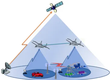
Fig. 1.10 Multilayer Architecture
As shown in Figure1.3 we are going to describe the reference architecture. The considered architecture is a hybrid multi-layer system composed of an On Board Process (OBP) Geostationary DVB-RCS Satellite which
cooper-16 1 Satellite and Hap multimedia Network
ates with a HAP mesh [30, 12, 13] . Both Satellite and HAP’s mesh cover with their spot-beams a set of terminals called Return Channel Satellite Ter-minals (RCSTs), with reference to DVB-RCS terminology [31, 2] . The overall platform is a DVB-RCS like architecture where the HAPs have been intro-duced. HAP is equipped with a regenerating communication payload, which increases platform complexity, as well as weight and power consumption. In this scenario the multicast concept has been introduced [32, 18] in order to evaluate the performance of our proposed multicast algorithm.
The chosen architecture is a DVB-RCS like architecture where multicast services are supplied to the end-users. As aforementioned illustrated several scenarious can be addressed. In order to achieve maximum of the network a scalable and reliable multicast protocol that interacts with the GA multicast algorithm shall be designed.
In the following chapters the multicast protocol and algorithm shall be illustrated taking into account that the multi QoS constraints problem has to be addressed. Our challenge is to make a perfect interoperability between protocol and algorithm that face with a multi-constraints scenarios, this per-mits to achieve a better resource management allowing a higher number of users and multicast groups to join into the network. Moreover, a better qual-ity shall be supplied increasing the overall qualqual-ity of the offered services and a higher user satisfiability is obtained.
1.4 Conclusions on Chapter 1
In this chapter a description about reference network is given. First of all a brief description about satellite network has been done. Reference archi-tecture is a satellite network based on DVB-RCS standard which is com-posed by an OBP satellite and several earth terminal capable to send and receive packets from the satellite architecture. This system permits to exploit high bandwidth services both in uplink and downlink. Moreover, thanks to the DVB-RCS and Multi Protocol Encapsulation protocol it is possible to easy interoperate with TCP/IP based networks. Satellite networks offer high coverage areas and robust connections. In order to enhance network perfor-mances and solve end-to-end delay a HAP meshes have been introduced. HAPs allow user to exploit high bandwidth service having low cost termi-nal. HAPs meshes are not worldwide available but where available permits to have easy configurable network and high configurability.
At the end the resultant network is composed of an OBP satellite that is connected with HAPs meshes and RCSTs. HAPs meshes and each single HAPs can communicate with other HAPs, Satellite and RCSTs while RCSTs can communicate with HAPs and Satellite too.
Hierarchical multilayer network is composed as herein shown: 1. First layer is composed by an OBP Satellite;
1.4 Conclusions on Chapter 1 17
2. Second layer is composed by HAPs meshes; 3. Thirty and last layer is composed by the RCSTs;
Multilayer network can be used to solve last mile problem, allowing where possible use of low cost terminal to connect at the network. Moreover, several advantages are supplied such as:
• high footprint, in fact Urban, Sub-Urban and rural areas can be covered by the same network;
• easy network configurability, in fact this network and in particular HAPs can be easy moved from an area to another easiest, saving time and cost of installation;
Several scenarios such as natural disaster, civil protection and war scenar-ios can be easy supplied with the proposed infrastructure due to the large footprint of the satellite network and thanks to the faster reallocation or installation of the HAP system that can be drive on site where their pres-ence is needed. Broadband networks allow several services to be addressed, for example in emergence scenarios high priority has to be assigned to life saving procedures. To do this tele-medicine, videoconferences, survive rescue services and resource sharing are only some examples of services that have to be available at first in order to rapidly organize local forces sending or-ders and knowledges from general headquarters to on field subsidiaries. A flexible and robust backbone permits to offer more services with an higher quality and allow operator to provide new solutions in different field of ap-plications. In accordance with that, multi-constraints QoS Multicast aware can increase network performances providing better resources management. Today, a higher number of users have access to the network and a better management avoids to overload the wired terrestrial networks, which are overloaded for several reasons, herein some of the are reported:
• growth of the multimedia services requestes in terms of resourses and time management;
• increase of access due to the paradigm every where-every time;
• increase of the on-demand services and the spreading of the pay-per-view and internet tv;
• increase of the use of mobile devices;
• increase of the online gaming where a lot of users exploit network to meet known and unknown people to make a game over the network.
Chapter 2
Qos multicast aware on multilayer
hierarchical network
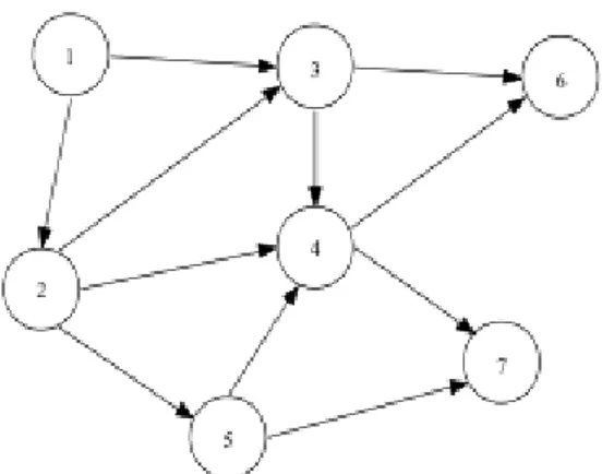
In this chapter QoS aware multicast issues are addressed. In particular, mul-ticast is herein illustrated in order to better understand algorithms proposal, which will be illustrated in the next chapter. First of all a brief description about literature proposal around QoS multicast is given. In this section sev-eral works have been briefly described in order to acquire a widely overview of the problem. When multicast protocols and algorithms are treated in terms of analytical representation a brief description about network representation is proposed. In fact, as further shown each network can be represented as a complete graph in which each router is a associated a tagged network node. To each node several terminals can be attached, this terminals are assumed to be end-users or sources of the multicast services. After that an analytical formulation of the multicast issues is given. This represents the starting point analyze problems that are treated in this work.
2.1 Multicast Routing Overview
The request of multicast services are increased in exponential manner in these last few years and in particular in the field of multimedia services. Multicast can reduce resources allocation and enhance network performance in terms of QoS. Key factor of the multicast is the capacity to reduce packets number that flows on the network. Only necessary packets are sent from the source, after that the network will provide to send necessary packets to other nodes until each destination is not reached. Multicast routes its packets following a multicast tree that is searched or built in order to reach each destinations.
In the multicast routing two entity works together with the main goal to distribute data among all nodes that belong to a multicast groups; these entities are the multicast protocol and the multicast algorithm, this last one can be completely disconnected from protocols, in this case the protocol has the task to trigger the algorithm when needed. Use integrated or independent
20 2 Qos multicast aware on multilayer hierarchical network
algorithm depends of network data to be distributed or from application type, moreover, several approaches exist to implements multicast such as centralized or distributed, shared or not, static or dynamic and so on.
With rapidly growth of hardware technologies and the rapid evolution of internet several types of applications have been developed. Once of the most common factor between these new applications and hardware is their complexity and requested quality. Often applications and services require a guarantee quality to be supplied. This issue is commonly treated with the QoS, which is used when services require feasibility, quality, robust connection error free transmissions and so on, which cannot be supplied with best effort services.
When QoS has to be addressed, some essential techniques have to be de-signed. For example
• Definitions and specification of QoS constraints and bounds have to be taken into consideration during a multicast sessions
• Multicast protocol and algorithm that addressed QoS have to be designed • Efficient Packet scheduling has to be designed in order to avoid buffer
overload and to adopt a certain fairness between class of traffic,;
• Resource reservation protocols have to be implemented in order to allow QoS services to be distributed on the network with a guarantee quality and continuity of the service.
• QoS management and multicast tree maintenance have to be addressed, in particular when high dynamic network have to be considered.
Some architectures have just designed, some of these are the Integrated Ser-vices (IntServ) and the Differentiated SerSer-vices (DiffServ)[6]. A coomonly known protocol is the Resource Reservation Protocol (RSVP), it has been de-signed to allow resource reservation in the unicast/multicast transmission[52]. QoS aware multicast routing tries to achieve a better multicast tree dis-tribution respecting some QoS constraints, which are going to offer some de-terminate performances. Therefore, a better resource utilization and higher applications standard will be achieved.In the IntServ with RSVP a protocols unicast/multicast has the main goal to build a path/tree, moreover, in those cases where the QoS constraints are not respected. hence the protocol has to look for another path/tree dropping oldest path/tree.
Another possibility is to allow connections that present a degraded QoS level, in this case RSVP checks QoS thresholds and if these thresholds are satisfied then the found solution is declared admissible, it is used to distribute network data flow between sources and destinations. QoS distributions is a very hard issues due to different reasons. The first for example is the different nature of the QoS metrics that generally a modern applications wishes to be respected contemporary.
In the Teleconference, on demand video, VoIP and web services a differ-ent kind of QoS parameter has to be supplied from the network, moreover, several bounds may have to be respected in order to guarantee a certain QoS
2.1 Multicast Routing Overview 21
level. In this scenario, routing is an hard issues because this kind of prob-lem are not treatable with polynomial routing algorithms. Moreover, in those networks where users and link’s state evolve rapidly is very hard to face prob-lem with algorithms and protocols that present lower complexity. In this case network topology changes due to nodes mobility and connection states, tree management increases it complexity because more protocol messages have to be managed to maintain routers and connection states updated. In those cases where a tree is degraded an alternative branches or an alternative tree have to be find to maintain a certain QoS.
2.1.1 Multicast Tree
The problem of multicast routing can be reduced to the problem of finding a tree into a graph (G), this tree is identified with the nomenclature of T.
T spans all vertices of the multicast group (M) on G. Multicast commu-nications can be of two types, that are source based and group shared. Main difference between the two category is that:
in the source rooted, multicast tree is optimized taking into account the source-specific multicast communications, instead in the group shared mul-ticast service is optimized taking into account whole mulmul-ticast group. In the other words in case of delay optimization for the two category we can sum-mary the following behavior [36]
• Source-rooted, the delay is optimized per each pair source - multicast mem-ber
• group shared, the delay is optimized per each couple of multicast member, therefore the average group shared delay is optimized
The multicast tree in order to offer a widely class of services that respect imposed bounds on QoS has to match the following requirements:
• Scalability : A good multicast tree is scalable in terms of network and group size. A reasonable amounts of time and resources have to be taken. • Dynamic group support : The dynamic of multicast group has to be sup-ported by the multicast and if necessary a tree rearrangement has to be performed to avoid multicast tree degradation due to member join/leave. • Survivability : The multicast tree should survive to several link or node
failures among the session life cycle.
• Fairness : It should provide a minimum QoS to each member of the mul-ticast group. It tries to dived the mulmul-ticast effort among the node that belong to the multicast path. In other words multicast tries to not over-load an area respect another one.
22 2 Qos multicast aware on multilayer hierarchical network
2.1.2 The life cycle of a multicast group
Multicast allows dynamic behaviors in groups management, it permits dy-namic member join/leave and dydy-namic sessions to be addressed. Multicast may have local or WAN access and memberships at the same time that are related to the same multicast groups. Moreover, mobility and wireless access make hard multicast treatment in order to supply constraints QoS services. Dynamic memberships allow us to have the following types of multicast (or host) groups:
• Dense groups have members on most of the links or subnets in the network; • Sparse groups have members only on a small number of widely separated
links;
• Open groups are those in which the sender/source need not be a member of the group;
• Closed groups allow only members to send to the group;
• Permanent groups are those groups that exist forever or for a longer du-ration than do transient groups;
• Static groups are those groups whose membership remains constant in time;
• Dynamic groups allow members to join/leave the group;
A network architecture that aims to provide complete support for QoS mul-ticast has to take into consideration transparent mulmul-ticast service, to do this specific requirements on the network implementation have to be considered. To demonstrate the different functionalities that such a network must pro-vide, The sequence of phases/steps relevant to the multicast session are: • Multicast group (session) creation;
• Multicast tree construction with resource reservation; • Data transmission;
• Multicast session teardown;
2.1.2.1 Multicast Group(Session) Creation
In the Group/sessions creation phase the first step is to assign an unique address to the multicast group such that the data of one group does not gone in conflict or overlaps others. Groups Id and Addresses are given to a multicast tree until its session does not expires. Similar to groups, group addresses are classified as either static or dynamic, depending on whether they are assigned permanently to a given group or assigned to different groups at different instants of time.
Commonly groups and addresses are treated in this way, a static addresses is assigned to the permanent groups, whereas dynamic addresses are assigned to those transient groups.
2.1 Multicast Routing Overview 23
2.1.2.2 Multicast Tree Construction with Resource Reservation Once the group is created, the next phase in the multicast sessions is the construction of a multicast distribution tree, spanning the source(s) and all the destinations, this process belongs to the QoS routing issues, once a path is chosen then the resource reservation process is started and all needed re-sources are reseved along the paths. Multicast route, is often formulated as a problem related to tree construction. Herein the mainly reasons to use tree is reported:
• The source needs to only transmit a single packet down the multicast tree. • The tree structure allows parallel transmission to the various receiver
nodes.
• The tree structure minimizes data replication, since the packet is replicated by routers only at branch points in the tree.
It has been demonstrated that the process to find an optimal multicast tree for a static multicast group can be modeled as STP in networks, which is shown to be NP-complete. An additional dimension to the multicast routing problem is the need to construct trees that will satisfy the QoS requirements. QoS routing and resource reservation are two important, closely related is-sues. Resource reservation is necessary for the network to provide QoS guar-antees. With QoS support, the data transmission of the connection will not be affected by the traffic dynamics of other connections that travel on com-mon links. Before the reservation can be done, a tree that has the best chance of satisfying the resource requirements must be selected.
2.1.2.3 Data Transmission
Once the above two phases have been completed successfully, data transmis-sion can begin. During the lifetime of the multicast sestransmis-sion and after that the multicast group has been created then it is possible to identify the following dynamics:
Membership: Since group membership can be dynamic, the network must be able to track current membership during a session’s lifetime. Tracking is needed both to start forwarding data to new group members and to stop the wasteful transmission of packets to members that have left the group, identi-fied as Constrained Online Multicast (COLM) routing. Tracking of member-ship dynamics may be done in either a flooding, centralized, or distributed scheme [?].
Networking: During the lifetime of a multicast session, if any node or link supporting the multicast session fails, service will be disrupted. This requires mechanisms to detect node and link failures, and to reconfigure (restore) the multicast tree around the faulty links/nodes. Note that multicast routing protocols based on underlying unicast routing protocols are as survivable as
24 2 Qos multicast aware on multilayer hierarchical network
the routing protocol. If the multicast routing protocol is independent of the unicast routing protocol, it must implement its own restoration mechanism [41].
Transmission problems: This could include events such as swamped re-ceivers (needing flow control) or faulty packet transmissions (needing error control). The traffic control mechanism, working in conjunction with the schedulers at the receivers and routers, is responsible for performing the nec-essary control activities to overcome these transmission problems.
Competition among senders: In many-to-many multicasting, when multi-ple senders share the same multicast tree (resources) for data transmission, resource contention occurs among the senders. This will result in data loss due to buffer overflow, thus triggering transmission problems. This requires a session control mechanism that arbitrates transmission among senders . 2.1.2.4 Group Teardown
At some point in time, when the session’s lifetime has elapsed, the source will initiate the session teardown procedures. This involves releasing the re-sources reserved for the session along all of the links of the multicast tree and purging all session-specific routing table entries. Finally, the multicast address is released and group teardown is complete.
2.2 QoS Aware Multicasting
In this section the state of art about QoS multicast will be treated. In partic-ular, QoS algorithms and protocols are described. First the multicast algo-rithms are faced and their issues are illustrated. Then the network protocols that provide multicast routing are proposed, in the protocols field several methods are available, as shown, exist centralized or distributed approaches or both. Due to the complexity related to the problem that we are going to face a description about the STP is given, in fact the class of problem treated belongs to the STP family.
2.2.1 Multicast Algorithms and Issues
Various classes of algorithms with different development techniques have been proposed. Some of them were developed with heuristic techniques, because these problems have a higher computational complexity. Multicast problems, with a lower complexity, consider simple routing with only one Quality of Ser-vice (QoS) metric and for this reason they can be solved with algorithms such
2.2 QoS Aware Multicasting 25
as Prim, Dijkstra or Kruskal[36, 26, 37, ?]. When a STP [58] is considered then an NP-Complete problem must be faced; in this case, in order to solve the multicast routing problem, alternative approaches could be used. These methods permit good solutions to be found, close to the optimum solution, which are called sub-optimal. Many studies have been made and good perfor-mances have been obtained from heuristic techniques. A new heuristic algo-rithm, called Bounded Shortest Multicast Algorithm (BSMA), is presented in [56] in order to build a minimum-cost multicast tree with delay constraints. Two variants of the cost function are considered: the first one minimizing the total link cost of the tree, and the second minimizing the most congested (maximal) link cost. Instead of applying the one-pass growing of the multi-cast tree used in previous works, Zhu et al. proposed an iterative optimization process to further minimize the tree cost that is monotonically achieved after a series of tree refinements. An algorithm, which has been taken as reference in the field of heuristics, is the algorithm proposed by Kompella et al. [57] , in which the Steiner tree problem is analyzed considering one QoS constraint. In particular, the constraint under study is a bounded end-to-end delay from the source to the destination and, moreover, it considers the minimization of the multicast tree cost. One of the first multicast routing GA was the Haghighat algorithm [27] . It is a QoS-based multicast routing algorithm based on the evolutionary principle which proposes to manage multiple QoS constraints in an efficient manner. Haghighat et al. proposed a connectivity matrix of edges encoding scheme for genotype representation. Moreover, they present some new implementation methods for mutation, crossover, pre-processing phase and random creation of initial population. Another algorithm is the Multi Objective Genetic Algorithm (MOGA) [15, 22, 28] . This algorithm is based on two different techniques. As is known, in order to gain some advantage, the GA must have a good fitness function. This permits a good possibility of mating the best chromosomes, so as to have better individuals in the next gen-eration. To perform the assignment of the fitness values to all chromosomes MOGA uses a technique of optimization, well-known in the field of Operative Research to minimize the multi-objective function. This function is composed of some terms that regard the cost, the delay and the bandwidth of the multi-cast tree that is to be evaluated. All multimulti-cast trees, represented by chromo-somes are evaluated by the fitness function that passes through various steps. A second class of problem resolution is represented by a specific branch of the Optimization Research, which is called the Tabu Search Approach (TSA) . TSA is another method to perform the multicast routing with a certain num-ber of QoS metrics; for example in the case considered the TSA can find a multicast tree that has the minimum multicast tree cost as proprieties and also respect for the maximum end-to-end delay allowed by an unspecified application. Algorithms that implement this type of heuristic to find a good solution are fast, in terms of execution time, but they do not assure that the solution found is optimal. The TSA proposed in [21] uses PRIM algorithm in order to move into solution space, but as is well known, this algorithm can