Facolt`
a di Ingegneria dell’Informazione
Corso di Laurea in Ingegneria Informatica
Dipartimento di Elettronica e Informazione
A Software Architecture Framework for
Model-Driven Big-Data Applications
Relatore: . . . Prof. Dr. Elisabetta DI NITTO
Correlatore: . . . Dr. Damian Andrew TAMBURRI
Tesi di Laurea di: Saeed TAJFAR matr. 803732
Acknowledgement
First and foremost, I would like to thank my supervisor, Professor Di Nitto. Her excellence as a researcher, perfect understanding, and guidelines signif-icantly helped me to complete this thesis. I am also deeply grateful to my adviser, Damian, for his professional guidance through this process.
I would especially like to thank my brilliant family for the love, support, and constant encouragement I have gotten over the years. In particular, I would like to thank Negar who was extremely patient while I was working hard to make this done, and I undoubtedly could not have done this without them.
Milano, November 2015
Sommario
Le tecnologie Big Data stanno rapidamente diventando un fattore chiave in industria. Tuttavia, i costi per utilizzare i benefici di Big Data possono essere immensi e vanno dalla necessit di superare una curva di apprendimento molto ripida, alla difficolt nel reclutare esperti, ai problemi connessi con loperativit di infrastrutture di supporto complesse. Queste difficolt rendono lo sviluppo e la gestione operativa di applicazioni per Big Data attivit molto complesse che richiedono unampia disponibilit di tempo. Per sostenere il lavoro di proget-tisti e sviluppatori questa tesi adotta un approccio guidato da modelli (model-driven). In particolare, questo lavoro sfrutta tecniche di analisi concettuale per dedurre i gli elementi rilevanti di ciascuna tecnologia Big Data e le relazioni e attributi tra tali elementi. Inoltre, utilizzando un approccio esplorativo, ab-biamo creato meta-modelli per produrre uno strumento di supporto che rende possibile per gli sviluppatori / designer di modellare una applicazione Big Data in maniera agile e veloce, senza dover spendere il costo inerente alla curva di apprendimento tipica per le tecnologie coinvolte. Lapproccio sviluppato stato valutato utilizzando tre casi di studio distinti. Questi hanno evidenziato una notevole riduzione del tempo e dello sforzo richiesto di implementazione e rende pi accurati gli aspetti inerenti allarchitettura e le caratteristiche tecniche dellapplicazione Big Data sviluppata. Di conseguenza, aziende interessate al-lutilizzo di tecnologie Big Data saranno in grado di rilasciare i loro prodotti sul mercato in una frazione del tempo normalmente necessario.
Abstract
Big Data technologies are rapidly becoming a key enabler in the industry. Yet, costs of being able to use benefits of Big Data is immense, ranging from learning curve, recruiting experts, infrastructures. However, one of the key barriers in Big Data is the time spent on developing Big Data applications and their effective deployment on an ad-hoc technology. To tackle the mentioned key obstacle, this thesis advocates the support of Big Data designers and developers by offering a Model-Driven support. In particular, this work uses conceptual analysis techniques to infer the relevant parts of each technology in big data and to clarify its relationships and attributes. In addition, using an exploratory approach, we created meta-models to produce a support tool that makes it possible for developers/designers to model a big data application in a fast and agile approach, without having to spend the cost of typical learning curve for the technologies involved. The approach evaluated using three different case studies. These showed a significant reduction in the time and effort required to deploy and makes more accurate aspects of the architecture and specifications of the Big Data applications. As a result, companies interested in the use of Big Data technologies will be able to release their products to market in a fraction of the time that is normally required.
Table of Contents
List of Figures xv
1 Introduction 1
1.1 The Context and Research Problem . . . 1
1.2 Research Approach . . . 2
1.3 Original Contributions . . . 3
1.4 Outline of the Thesis . . . 3
2 Background 7 2.1 Big Data . . . 8
2.1.1 Definition of Big Data Applications . . . 8
2.1.2 How Analytical Results Can be Consumed . . . 9
2.1.3 Big Data Opportunities . . . 9
2.2 Software Engineering for Big Data . . . 11
2.2.1 Unified Modeling Language . . . 11
2.2.2 Model Driven Architecture . . . 14
2.2.3 Domain Specific Languages . . . 15
2.2.4 Model Transformations . . . 17
2.3 Technologies for Big Data in Our Work . . . 20
2.3.1 Hadoop Map Reduce . . . 22
2.3.2 Oryx 2.0 . . . 28
2.4 TOSCA as a DSL . . . 31
2.4.1 TOSCA building blocks . . . 32
2.4.2 TOSCA Artifacts . . . 33
3 Thesis Work in the Context Of DICE Framework 37
3.1 DICE Project . . . 37
3.1.1 DICE Layers . . . 37
3.2 An Overview of Approach . . . 39
4 Hadoop MR and Oryx 2.0 Technology-Specific Packages 43 4.1 Hadoop Map Reduce DTSM layer . . . 43
4.1.1 Components of Hadoop Map Reduce DTSM . . . 46
4.2 Oryx 2.0 DTSM layer . . . 53
4.2.1 Components of Oryx 2.0 DTSM Layer . . . 55
5 Hadoop MR and Oryx 2.0 Deployment-Specific Packages 63 5.1 ModaClouds . . . 63
5.1.1 ModaClouds and DICE Deployment Layer . . . 63
5.2 Hadoop Map Reduce DDSM . . . 65
5.2.1 Components of Hadoop Map Reduce DDSM . . . 67
5.3 Oryx 2.0 DDSM layer . . . 70
5.3.1 Components of Oryx 2.0 DDSM layer . . . 72
5.4 TOSCA General Metamodel . . . 76
6 Hadoop MR and Oryx 2.0 Model Transformations 79 6.1 Hadoop MR DTSM to DDSM Model Transformation . . . 79
6.2 Oryx 2.0 DTSM to DDSM Model Transformation . . . 81
6.3 DDSM to TOSCA-YAML Transformation . . . 82
7 Evaluation 85 7.1 Goals of the evaluation . . . 85
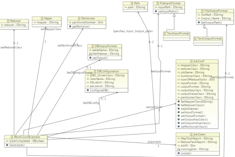
7.2 Hadoop Map Reduce Word Count Application . . . 85
7.2.1 Hadoop MR WordCount DTSM Model . . . 86
7.2.2 Hadoop MR WordCount DDSM Model . . . 87
7.3 Oryx 2.0 ALS Application . . . 90
7.3.1 Oryx 2.0 ALS DTSM Model . . . 91
7.3.2 Oryx 2.0 ALS DDSM Model . . . 92
8 Adding Technological Extensions 97 8.1 Required Tools . . . 97
8.1.1 Modeling tool . . . 97
8.1.2 Model Transformation Tools . . . 97
8.2 How to Extend DICE Layers . . . 98
8.3 Extending Model Transformations . . . 99
8.4 Posidonia System . . . 101
8.4.1 An Abstract review to Posidonia DTSM layer . . . 101
8.4.2 Posidonia DDSM layer . . . 103
9 Conclusions and Future Works 107 9.1 Observations and Lessons Learned . . . 107
9.1.1 Teamwork as an effective means . . . 107
9.1.2 Improved knowledge on Technologies . . . 107
9.1.3 Using an Online Repository . . . 108
9.1.4 Some Management Lessons . . . 108
9.2 Approach Limitations . . . 108 9.3 The Results . . . 109 9.4 Future Work . . . 110
Appendices
111
A Modeling Implementation 113 A.1 Introduction . . . 113A.2 Technology-Specific Modeling . . . 113
A.3 Deployment-Specific Modeling . . . 114
B Model Transformation Implementation 117 B.1 Introduction . . . 117
B.2 Model-to-Model transformation project . . . 117
B.2.1 DTSM to DDSM transformation of Hadoop MR . . . 118
B.2.2 DTSM to DDSM transformation of Oryx 2.0 . . . 119
B.2.3 DTSM to DDSM transformation of Posidonia . . . 121
B.3 Model-to-Text transformation project . . . 122
B.3.1 Hadoop MR TOSCA-YAML Blueprint . . . 125
B.3.2 Oryx 2.0 TOSCA-YAML Blueprint . . . 128
List of Figures
2.1 Xtext Architecture . . . 19
2.2 Typical Hadoop Cluster . . . 26
2.3 Kafka Topic and Partition . . . 30
2.4 Kafka Topic and Partition . . . 31
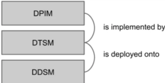
3.1 DICE Layers and Their Relationship . . . 38
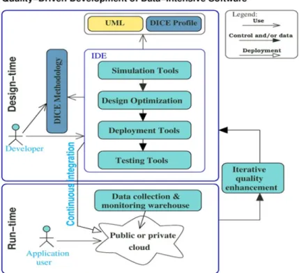
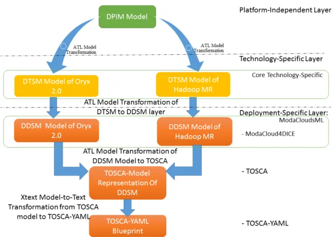
3.2 DICE Quality-Driven Development of Data-Intensive Application 40 3.3 Solution Architecture of Thesis . . . 41
4.1 Hadoop Map Reduce DTSM . . . 45
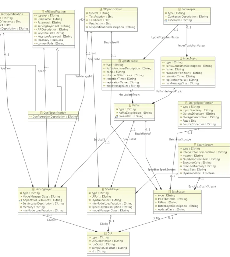
4.2 version 2 of Oryx 2.0 DTSM layer . . . 54
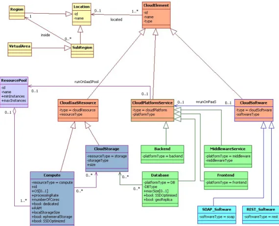
5.1 ModaCloudsML CPIM (Purple: resources, Green: platforms, Cyan: softwares, Yellow: locations, Orange: elements) . . . 64
5.2 Hadoop MR DDSM layer . . . 66
5.3 Oryx 2.0 DDSM layer . . . 71
5.4 TOSCA Metamodel . . . 77
7.1 Hadoop MR WordCount Application DTSM Model . . . 87
7.2 Hadoop MR WordCount Application DDSM Model . . . 88
7.3 Oryx 2.0 ALS Application DTSM Model . . . 92
7.4 Oryx 2.0 ALS Application DDSM Model . . . 93
8.1 Posidonia DTSM layer . . . 103
Chapter
1
Introduction
In this Introduction chapter, we will discuss the motivation of the thesis. We will discuss the problems and highlight the main issues that exist and the innovations used to tackle them by referring to the chapters in outline section.
1.1
The Context and Research Problem
Nowadays, there are a lot of different technologies for Big Data that are coming out by a very high rate and as they are usually frameworks, they are of course quite complex. Also, one can consider a distributed system with different nodes and specific communication mechanisms and these means that in order to use these technologies, one really needs to learn them and to be proficient with them. The things would be even more complicated in a complex appli-cation as one needs to exploit more than one technology. The assumption of DICE, which is the framework we are working on, is that if we model these technologies and offer these models to the designers and developers, they can incorporate these models of technologies in their architectural models more easily and therefore they can be helped in design phase. Moreover, according to the DICE assumption, the models that we have of the applications that are built on top of the technology can be transformed into a deployment recipe that can be used at the deployment time to actually deploy and run the system. The research’s main question of current thesis was, ”‘Can I produce models of
Hadoop Map Reduce and Oryx 2.0 that can be led to a deployable applica-tion?”’
1.2
Research Approach
As mentioned above, the research problem is to develop models of technolo-gies that led to a deployable blueprint by having big data application on top of that technologies. The approach is to study the technologies to come up with models of these technologies. To do this step, to what concerned about the technologies, we have been using reverse engineering, partially automated through the usage of some tools and partially manually through the direct analysis of code and documentation, and so on. Then since we had to de-ploy these technologies on cloud resources, we had to study also the cloud resources; for instance, how they look like and how can be described. To do so, we started form Modaclouds on one side and TOSCA on other side. Modaclouds is a project that provides some models for the resources, TOSCA dose something similar at using a language that has been standardized. We have been trying to understand if the concepts of Modaclouds that is already expressed by models could be mapped into TOSCA. So we have done an analy-sis between ModacloudsML and TOSCA. As these analyanaly-sis were successful, we understood that it is possible to define transformation from Modaclouds model into a TOSCA blueprint. In the end, at the first part we built metamodels for those technologies, applying a reverse engineering approach then we studied the state of the art for what concerns about cloud resources and we decided to adopt Modaclouds and we check if the concepts of this model can be mapped to TOSCA through the analysis. Next, we built model transformations that allowed us to start form technologies and go to the deployable models for these technologies and then model-to-text transformation used that allowed us to derive TOSCA blueprints given models of applications on top to be deployed on certain cloud resources.
It is important to mention that this work is the complementary and continu-ation of the efforts that is done by one of my colleagues, where the platform-independent and technology-specific layers of Oryx 2.0 modeled [29]. This research continued with respect to technology-specific layers of Hadoop Map Reduce and refinement of Oryx 2.0 technology-specific layer and modeling the
deployment-specific layer of the mentioned technologies to get into a deploy-ment recipe as a result.
In Addition, XLab which is one of the partners of DICE project1 used the
blueprints produced as the results of this thesis in order to perform deploy-ments using Cloudify2 orchestration engine.
1.3
Original Contributions
Given what is described before, in summary the original contributions of this thesis are as following:
• definition of metamodels of two technologies
– technology-specific matamodel of Hadoop MR modeled, also technology-specific metamodel of Oryx 2.0 refined
– deployment-specific metamodels of Hadoop MR and Oryx 2.0 mod-eled as an extension of ModacloudsML within a package that con-tains deployable elements, that is called Modacloud4DICE
• all the transformations that are needed to make sure that applications that are built on top of these technologies can become deployable
– model transformations from technology-specific to deployment-specific layers
– model transformations from deployment-specific to TOSCA where TOSCA blueprint is represented as a model
– generating the DICER tool that takes TOSCA model representation and produces an equivalent json and YAML output
• also, to validate these contributions, three case studies investigated
1.4
Outline of the Thesis
Consistently to what we have explained in this chapter, the thesis is organized as follow:
• In Chapter 1 provided an overall overview on the whole work by defining the problems and the general decisions that are taken to address them and finally, the contribution of the thesis is discussed
• In Chapter 2 the background of big data applications are depicted by cov-ering the definition of big data applications and their benefits to variety of subjects. In the next sections, the concepts of Software Engineering that contributed to this work is illustrated. Afterward, the technologies of big data in this work are discussed and finally, TOSCA as a domain specific language is explained
• Chapter 3 describes DICE framework and its layers and specifies the fact that this thesis is following its concepts. In addition, the general archi-tecture of the work is depicted to help the readers about the relationship that exists between different original contributions of this thesis
• Chapter 4 describes the first original contribution. There, Model Driven Engineering techniques is used to define the DTSM layers for Hadoop Map Reduce and Oryx 2.0 clusters and we have illustrated their compo-nents, and attributes of each component and their relations
• Chapter 5 describes the second original contribution of this work. There, also MDE is employed to define the DDSM layers of Hadoop Map Reduce and Oryx 2.0 clusters and illustrated their components and the attributes of those components and their relations
• Chapter 6 describes the third original contribution of this work. There, Model-to-Model and Model-to-Text transformations between DTSM layer and DDSM layer of both technologies are discussed
• In Chapter 7 the adopted solution of Hadoop Map Reduce and Oryx 2.0 is examined on two distinct case studies. The first one is WordCount application of Hadoop MR which counts the number of occurrences of each word in a text file, and the other is ALS application of Oryx 2.0 which deals with both stream and batch data analysis to apply machine learning algorithms. Furthermore, the third case study is illustrated which proves the extension capabilities of the contribution to support other technologies
• Chapter 8 describes the techniques and packages that are required to extend the framework to support more big data technologies both for modeling and model transformation part of the framework
• In Chapter 9 describes the lessons learned through the work on this thesis. In addition, it enumerates the limitations that are known to the results of this work. Next, the conclusion of the thesis is discussed. There, we will depict the results of this work by recalling the problem which introduced in introductory chapter, and we try to highlight the main innovations that is used to tackle the problems. Furthermore, we will discuss about the future works that can be done by other colleagues.
Finally, in Appendix A and B, the implementation projects that are devel-oped to model the architecture of technologies in DICE and the dependencies between those projects are discussed. Afterward, the TOSCA-YAML recipes which are final results of this work are depicted.
Chapter
2
Background
Contents
2.1 Big Data . . . . 8
2.1.1 Definition of Big Data Applications . . . 8 2.1.2 How Analytical Results Can be Consumed . . . 9 2.1.3 Big Data Opportunities . . . 9
2.2 Software Engineering for Big Data . . . . 11
2.2.1 Unified Modeling Language . . . 11 2.2.2 Model Driven Architecture . . . 14 2.2.3 Domain Specific Languages . . . 15 2.2.4 Model Transformations . . . 17
2.3 Technologies for Big Data in Our Work . . . . 20
2.3.1 Hadoop Map Reduce . . . 22 2.3.2 Oryx 2.0 . . . 28
2.4 TOSCA as a DSL . . . . 31
2.4.1 TOSCA building blocks . . . 32 2.4.2 TOSCA Artifacts . . . 33 2.4.3 TOSCA-YAML Terms . . . 33
2.1
Big Data
2.1.1
Definition of Big Data Applications
Big Data concern large-amount, complex, growing data sets with multi-ple, autonomous sources, networking, data storage, and data collection ca-pacity, These data are rapidly expanding in all science and engineering stream,including physical, biological and medical sciences [34]. The speed of generating data is growing in a way that makes it difficult to handle such amount of large data. The main challenge is that the volume of data is in-creasing so fast with respect to capabilities of computing resources. Big data requires exceptional technologies to efficiently process large quantities of data within tolerable elapsed times. Technologies being applied to big data include massively parallel processing (MPP) databases, data mining grids, distributed file systems, distributed databases, cloud computing platforms, the Internet, and scalable storage systems [26]. The concept of big data by itself does not mean that the volume of data is too large, yet it more focuses on the concept that there are processing difficulties to infer new knowledge from it. For ex-ample, even a text file with ten millions of records is not too large with respect to its size, but when it comes to processing the contents of it, it would be challenging.
Big data comes with the following properties:
• Variety: Data being produced is coming from different data sources like, web pages, web logs, social media, and sensor devices, etc. it is hard for traditional analytical computing devices to process these kind of data which could be in raw, structured, unstructured, or semi-structured [17] • Volume: Now days, the data existing in Petabytes. It is supposed to be increased in zettabytes in next few years [17]. For instance, social networks produce terabytes of data each day and obviously it is hard to handle this volume of data by using the traditional data processing techniques
• Velocity: velocity references to the velocity of generation of data or how quick the data is generated and processed [34]. The speed in which data
is being generated is extreme. Sensors, signal receivers, machine learning algorithms, and so on are precipitately generate streams of data
2.1.2
How Analytical Results Can be Consumed
Nowadays, it is critical to organization to use the historical data that they have collected through years of their activity to infer new knowledge that is hidden and unknown inside those data also, this claim is true about the streaming data to find the patterns that can be used to to predict concepts, events, trends, opinions, and so to support decision makers [25]. The output of these analyzes can be used in different ways based on the needs of the company. Generally, there are three kinds of usage of outputs of big data analysis:
1. Level 1 (L1), supervised actionable outputs: the output of analysis will be returned to an individual as a supportive recommendation to human, then it would be the decision of human either to make that recommen-dation actionable or not
2. Level 2 (L2), semi-supervised actionable: at this level, the output of the big data analysis is more respected by human and the machines are allowed to use the output results to make actions on their own, yet the results of these action are observable by human and they can be reverse back if needed. For example, in case of streaming data analysis, machines are able to detect if an email message is either a spam or not. Although, as it happens that machines make a mistake on this detection procedure, it is possible for the users to regret the result and move that message into their inbox.
3. Level 3 (L3), unsupervised actionable: at this level machines are fully trusted and there is not any human intervention to reverse back the results; as an instance, movie recommender systems can classified in this category
2.1.3
Big Data Opportunities
The interesting values of big data is now recognized by organization and gov-ernments. Actually, the exploring of big data enables the stack holders to
be more competitive and to add value for a variety of sectors in their com-pany [3]. Many researchers have done lots of surveys on the opportunities of big data. In this section, we make a review on how big data could bring beneficial ramifications to different organization, like health, research, commerce, and agriculture.
Healthcare Organization
The analysis on big data can bring valuable results to healthcare organiza-tions. Big Data analytic can revolutionize the health domain by supporting the optimization of operational services, by offering decision support tools and by decreasing the high cost of this sector. [21] In the following some of these effects are enumerated:
• Optimizing health services: big data analysis helps to find which depart-ment need more attention. It helps to assess the quality of service and the performance of units of the organization to reveal the requirements of human resources or equipments
• better understanding of disease patterns: data analysis of large sources of information on DNAs can assist to understand the pattern of different diseases. Such information can help doctors to predict optimal cure for certain diseases.
• support medical prescription: analysis of the historical data on surgeries and their results can help the doctors to find the be medicine that is proper to a patient that had the same problems and his profile is more similar to historical patients
Trading Organizations
Data has a significant role in trading companies if it perfectly exploited and analyzed. Thanks to big data technologies now days it is possible to integrate and analyze even large data sources; for instance, the data that is generated by social media or sensors of mechanical machines. This makes it possible for companies to be more competitive and to increase their profits. In general, Big Data mining allows a better monitoring of macro and micro economy and help decision makers to catch commercial opportunities and to anticipate
recessions [22]. Furthermore, enterprises can exploit Big Data through multiple stages according to their maturity level: [30]
1. Instead of just monitoring the internal business processes, enterprises can exploit the results of Big Data analysis to understand customers behaviors and to enhance their commercial strategies and products
2. By gaining a certain maturity, enterprises are willing to do better by optimizing their processes and by detecting business opportunities
3. The next maturity level is when the enterprise is capable not only to optimize its business model but to monetize the value of the collected Big Data. This can be done by making additional profits through the reselling of data and analysis results. Another way is to exploit the Big Data insight to enhance products and customers experience in stores and online
Agriculture
There could be obtained valuable results of big data analysis from data of agriculture. Those results can be helpful to have more optimal food production plans; for example, with respect to whether conditions and raining pattern of a region.
2.2
Software Engineering for Big Data
What is big data software? How is it different than non-big-data software? Can it be engineered? Answering these questions requires exploration of the term big data for achieving consensus and arriving at a definition of big data software [25].
2.2.1
Unified Modeling Language
Finding the right modeling language for big data applications is a challenging task. Such a language should be rich enough to be able to describe the connec-tion between big data applicaconnec-tion components and their attributes. Currently,
using Unified Modeling Language is one of the most commonly explored ap-proaches in system modeling [28]. Using UML modeling is vastly used in every development industry form small to large scale projects. Actually, UML is a known and approved Meta-model based technology [33]. In addition, it is possible to extend it with data analysis and processing concepts so that it is suitable to both defining the architecture of a big data cloud application and to generate code for it [8]. This extension of UML is called UML profile that allows adding new features to the language in order to represent the architecture of big data application.
Meta Model
A meta-model is composed of entities and relationships. Entities represent el-ements of the model of a system, and relationships represent relations between those model elements [18]. It is possible to use these entities and their rela-tionships to simulate a system; for example, in case of Big Data technologies to model the entities of each technology for the desired purpose. Such extended UML diagrams can be classified as a new Domain Specific Language (DSL). At the beginning of modeling a system and analyzing it, the architecture of the system and how its elements work together is not known. The idea on how to address this issue is to gradually study the different parts of the system and to know how they interact with each other. This gradual development is important in defining the meta models of large scale systems.
”‘The big data challenge is not always about massive loads of data, but instead massive variation and feeding a lot of different sources into a single applica-tion. Now to make such an application you both need a lot of connectivity capabilities and a lot of modeling flexibility. Those are the two aspects where Apache MetaModel shines. it makes possible for you to build applications that retain the complexity of your data even if that complexity may change over time.”’1
The profile mechanism of the Unified Modeling Language (UML) was de-signed to support the refinement approach to DSML design [31]. So, the
1
generated UML profile could not violate the fundamental rules of standard UML.
Stereotype Concept
The concept of stereotype of UML gives the ability to make a relation between our domain specific tools to UML standard definitions. For example, we can represent the concept of a database node by tagging a class Node and defining its specific constraints and attributes. A stereotype definition consisted of a user-defined stereotype name, a specification of the base UML concept (e.g., Class) for the stereotype, optional constraints that specified how the base concept was specialized (e.g., a Class that can have at most one parent), and a specification of the semantics that the stereotype adds to the base concept semantics [31].
Profile Concept
The concept of profile is defined as a set of stereotypes that are related to each other. A domain specific modeling language can be defined by a profile. The profile should provide domain specific concepts. For instance, a profile might be a language for Big Data applications. This profile can provide domain specific concepts such as Mapper, Reducer, Partitioner, etc. instead of general UML concepts like Class, etc.
The following concepts should be considered when one decides to instantiate a profile:
1. Defining UML profiles: To define a UML profile the building blocks should be made: a metamodel and the profile itself. The process starts with defining the metamodel of the specific domain first and then this artifact should be translated into profile. It is very important that DSML to be conformed to UML. Otherwise, may be defining DSML by using UML could be an issue
2. The metamodel: The purpose of metamodel is to specify the main con-cepts of DSML. So, it is very important to get the knowledge about the specific requirements of the considered domain at first step. Otherwise, may be the experts loose the concentration of what should be specified
by the domain. Since, it would be better to focus on the domain instead of UML metamodeling, not to be involved in the complexity of UML definitions at the beginning
3. Mapping the metamodel to profile: As the metamodeling of the sample is ready, then the process of mapping the metamodel concepts to profile concepts will start. For example, in Hadoop MR may be we conclude that mapper concept could be represented by UML Class and to represent its specific features by attributes of the class
In short words, UML is powerful enough to provide the foundations to define a wide range DSMLs by its provided concepts.
2.2.2
Model Driven Architecture
Current trends in the evolution of software development process are closely related with the increasing complexity of software systems. This motivates software engineers and system developers to find an alternative solution for software system design and development [23]. In this section, we discuss what is Model Driven Architecture(MDA) is and what is its fundamental concepts. Before starting with MDA, it is seems wise to have an background of this approach, using this way makes us to have a better understanding of benefits of MDA. MDA, was introduced by OMG in 2001 to satisfy the needs of software industry [14].
MDA uses formal models to define software solutions, by using a customized set of tools. It imposes precise design and architectural patterns. the MDA approach considers models as central part of the development process (assum-ing that model represents a set of diagrams, used to express the whole software system) [24]. In fact, MDA is a further step in the evolution of software devel-opment that tends to improve each step of the traditional software develdevel-opment life cycle: system specification, architecture, design, development, deployment, maintenance, and integration based on formal modeling [14]. More specifically, MDA can be proposed as a set (framework) of technical standards developed by OMG. OMG provides the guidelines that enables the application of MDA in accordance with the appropriate tools and processes [14]. One of the interesting
specifications of MDA is the transformation between the models; for instance, to get into a more specialized model by model to model transformations.
During the first steps of software development the main aim of the devel-opment team is to find the requirements of the targeted system. Afterward, these requirements should be modeled by UML to produce the initial formal representation of the system. This layer not only defines the requirements of the software system that is Platform Independent Model(PIM), but also it provides the foundations that are required for transformation to Platform Specific Model(PSM) where the requirements of the previous level are going to be mapped to functionalities of a specific technology; for example, Hadoop Map Reduce. After platform specific models created, the last layer that is run-time model should be designed; for instance, deployment specific model that is called Implementation Specific Model(ISM). In following, the building blocks of Model Driven Architecture is depicted [35]:
• A model repository, where models of the software is saved
• One or more domain modeling languages; for example, Unified Modeling Language (UML)
• One or more workbench environments; for instance, Eclipse editor • One or more modeling tools; like, Eclipse Modeling Framework (EMF) • One or more transformation tools; like, ATLAS Transformation
Lan-guage (ATL)
2.2.3
Domain Specific Languages
By emerging new technologies the need of more special tools to fulfill the needs of companies show up. In software engineering, technologies are becoming more and more complex this process makes increasing the demand of tools that make the life of developers easier. The essential feature of all such tools is that the specialized domain concepts of a specific technology is considered in opposed to general tools which cover different domains of problems. This can make the programmer’s job easier; because, it is more related to the problem specific area of a complicated technology. Furthermore, the time and effort required
of systems the variability cannot be efficiently described with a feature model-based configuration. Rather, it is more suitable to define a custom language to bind the variability, a language typically limited in scope and is specific to the task at hand. Such a language is called a domain specific language (DSL) [37]. In case of Big Data, the lack of a modeling design tool for deployment is a major detriment and should be considered into account whether or not to define a modeling tool for developers to suggest them feasible deployment options of the technology in hand even if there is enough expertise available.
A more prudent approach to make such a domain specific tool is to design it on an already existing technology, by having a proven modeling language in hand.
There are three primary methods for defining a domain specific tool:
1. Bottom-up approach, by going into details of each existing target tech-nology to understand its different components to make a domain specific modeling tool to cover its concepts.
2. Top-down approach, by considering the theoretical documentation of such domains as a high level view of different technologies.
3. Definition of a new modeling language from scratch [31].
Obviously, the last one has the capability for the most direct solution to define a domain specific tool. However, it has serious drawbacks. Let’s say that this approach is time consuming and requires a lot of effort of especially trained experts. Furthermore, it is generally more difficult and expensive to develop tools for modeling languages than for programming languages, due to the usu-ally more sophisticated semantics behind many modeling language constructs. For example, a tool that compares two state machine models must understand the semantics of state machines [31]
Also, in the second method a wide variety of technologies could be considered which makes it very complex for the experts. So they have to focus on general interesting functionalities of current technologies. This method could be used as the complement of the next method, together.
For these reasons, the first method based on going deep in each technology is often the most effective solution to make domain specific modeling tools.
In addition, in this work UML as a modeling language is employed and ex-tended to model the architecture of big data applications as part of the DICE profile. Hence, it could be inferred that DICE profile is a DSL, also which is specific for big data applications.
2.2.4
Model Transformations
Model to Model Transformation
In the context of MDE, the models that are consistent with designed meta-models are the main artifacts, what if there is a need to transform a model to another one? Are there tools which can support us to transform a model of source metamodel to an instance of target metamodel? For sure, this tool plays an essential role in Model Driven Engineering! As a fact, a number of model transformation languages have been designed and introduced to com-munity [36].
In Model Driven Engineering, there are some fundamental concepts that it seems interesting to know more about them. Model, and Metamodel:
• Model: it represents a system and the different characteristics of its components; for instance these characteristics can be shown by using XML, JSON, or YAML metal-languages
• Metamodel: it is actually the foundation of modeling language that can be expressed by a model of that system, they define the abstract syntax of modeling languages [15]. conformsTo, is defined as the relationship between a model and its metamodel. Furthermore, metamodels are de-signed by using some modeling languages like UML.
In this work, in order to perform model to model transformation, the ATLAS Transformation Language is employed to perform the transformation between different layers of the profile; for instance, DTSM to DDSM, or DDSM to TOSCA metamodel.
ATLAS Transformation Language
Atlas belongs to project of open source, it is a one-way model transformation language, and it uses OCL to describe constraints [11]. It is a tool that can be
used for model to model transformation in MDA. Furthermore, it is intensively rule based. Through ATL rules, developers can generate a target model based on a source model, both source and target models of ATL must be consistent to their own metamodels. In the following the general structure of an ATL model is discussed:
• Header: this part of the ATL model defines the module name. Note that, the ATL file name of module code in the module must consistent with the module’s name [39].
• Helpers: ATL helpers could be considered as Java functions, it is possible to perform minor computations by them
• Rules: Two kinds of rules exist in ATL, one is matched rules that are those rules which are called during the runtime and imperative rules are those rules that are called by the programmer in ATL model
Model to Text Transformation
In Eclipse, the Graphical Modeling Framework (GMF), is a tool set which can be used by developers to generate graphical models, it facilitates to define graphical meta models. But, in some cases graphical meta models are not enough, and many problems can be addressed by textual representation with concrete syntaxes. In Eclipse, this area is addressed by Textual Modeling Framework (TMF), which makes it possible to generate textual syntaxes from GMF meta models.
Xtext as a Model to Text Framework
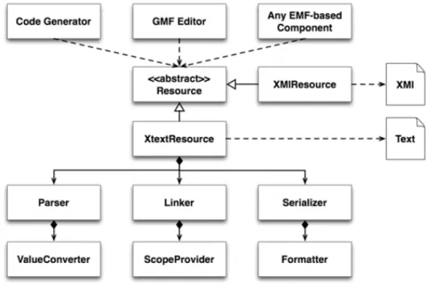
Xtext is a framework which allows you to quickly develop tooling for a textual language.The architecture of Xtext is depicted in Fig.2.1. The kind of language that can be produced by Xtext ranges from small Domain-Specific Languages (DSL) to full General Purpose Languages (GPL). This also includes textual configurations files or human-readable requirement documents. The motiva-tion for having good tooling is to increase the readability, write ability and understandability of documents written in those languages. Starting with a grammar definition, Xtext generates a parser, serializer and a smart editor for
the language2.
The grammar language is the corner stone of Xtext. It is a domain-specific language, carefully designed for the description of textual languages. The main idea is to describe the concrete syntax and how it is mapped to an in-memory representation - the semantic model. This model will be produced by the parser on-the-fly when it consumes an input file3.
Xtext can automatically derive the grammar from an existing Ecore model. It is important to keep the Ecore model stable; because if the Ecore model changes, then the automatically generated grammar will not consistent with with that meta model and the generated instances of that meta model will be unknown to the grammar.
Starting from this grammar, Xtext generates an ANTLR parser [4]. The
Figure 2.1: Xtext Architecture
generation of the abstract syntax tree is handled by Xtext well. There is a direct correspondence between the names used in the rules of the grammar and the Ecore meta model classes.
Usually GMF stores a model of Ecore metamodels in XMI files, in case of model to text transformation, it is possible to inject to the grammar this XMI instance of the source meta model and then it would be the duty of grammar to generate the text of target DSL. In this case developers can use the stand alone
instance of the grammar and write some code to use the provided XMIResouce of EMF to generate the target DSL and save it back into a file. For instance a yaml text file in case of TOSCA-YAML.
2.3
Technologies for Big Data in Our Work
Considering the big data, there are huge number of sources for data. Al-though these days the problem of storage capacity is solved by a good percent-age, yet the need of efficient and reliable data processing systems is critical. The traditional data processing systems are not adequate to process big data; for instance, relational databases are unable to handle analysis of big data. Traditional parallel database technology pursues a high degree of consistency and fault tolerance as to rely on parallel computing to improve the speed of data processing, but according to the theory of CAP (it is impossible for a distributed system to guarantees of Consistency, Availability, and Partition tolerance simultaneously), it is difficult to ensure the availability and scalabil-ity [20]. Basically, the process of big data in some cases is like traditional data. The main difference is that in each processing stage big data can use parallel processing such as MapReduce which can deal with large amount of unstruc-tured data [9]. The general pattern of Map Reduce is to split the data into different servers and lastly to merge the results after which parallel processing terminated. At first, MapReduce realizes big data parallel processing by using a large number of cheap servers [20]. The advantage of map reduce is that it is highly expandable and also its parallel processing ability, as it distributes the processing between salve nodes on the cluster. At this point we are going to focus on the steps of data processing
• Data Acquisition: nowadays it involves more than moving data from sources to organization repository. In fact, it is not possible for companies to store data from each source that they have access to. What they can do is to sniff those data and to analyze it right away, and to save just the results of computations.
Also, if company feels that it is necessary to store the incoming data, the first thing that should be considered is to how to convert those data into a format that is understandable by Hadoop or other processing tool of
the company. As the traditional way of collecting data is not sufficient, new methods should be used for data acquisition:
1. collecting system logs: many organizations use their tools to collect data, yet some of the are used in collecting logs of the systems, like Chukwa of Hadoop and Scribe of Facebook. These tools can be used for data acquisition of hundreds of thousands of mega bytes per seconds
2. collecting unstructured data from network: it refers to the data that can be collected through the network; for instance, data from web pages that is collected by web crawlers and saved
• Data pre-processing: there are three steps of data pre-processing. They are Extraction, Transfer, and Load(ETL). The extraction phase is deal-ing with collectdeal-ing data from different data sources and the next step is to transfer and load those data into a target database or the corresponding file storage like HDFS, that would be the basis for data analysis. In the following, the steps are discussed in a more detail:
1. Data extraction: data can be extracted from different distributed sources; for instance, by using the interfaces that are provided by those data sources
2. Data transformation: The data that is extracted in previous step converted to be compatible with the structure of the target system; for instance, by cleaning and data conversion methods
3. Data loading: The converted data will be loaded to the target stor-age in this step; for instance, HDFS or local file system. This step is a bulk loading process
• Data Storage: the size of data is so immense in case of big data that traditional storage systems have some difficulties to deal with. One of the key elements of big data is to store data in a reliable and fault tolerated way. Also, in the context of big data, the speed of data production can exceed storage capacity. With the help of distributed storage, it is possible to handle this issue:
1. File storage for big data: the two famous technologies for big data storage are Google GFS [12] and Hadoop HDFS [6]. They are both distributed storage. Also, they use master and slave nodes to man-age their clusters, means that master node keeps the meta data of the distributed files on the slaves and also responses to requests, and slave nodes keep the real data inside them
2. Management perspective: it is hard for relational databases to deal with big data and they cannot handle the stress and mass data storage
• Data mining: big data mining adopts parallel processing like map reduce, it distributes the job between slave nodes and then merges the results that is produces by slave to make the final result with out interaction between slave nodes [19]. It is critical that when the data amount in-creases, we only need to add distributed service nodes without changing algorithm of data mining [20]. The typical data mining technologies are:
1. Hive: it is a data warehouse platform on Hadoop. it defines the query language HQL that is like SQL and transforms SQL like queries into map reduce function of Hadoop map reduce
2. Mahout: the goal of mahout is to make it easy to build machine learning algorithms and applications that are scalable
• Visualization of results: According to [38] the result display of big data pays more attention to interaction and visualization. The final results of analysis play an important role in decision making process of the top level managers of each company; as an example, they can decide either to invest on a specific market or not based on the predictions that made available by historical data analysis for next months or years
2.3.1
Hadoop Map Reduce
The Apache Hadoop project develops open-source software for reliable, scal-able, distributed computing. The Apache Hadoop software library is a frame-work that allows for the distributed processing of large data sets across clusters of computers using a simple programming model [26], it can be used in order to
write applications which are dealing with huge amounts of data, i.e. terabytes of data, on a cluster of nodes. MapReduce splits the input data into separate, independent chunks that will be uploaded into a special file system called HDFS. The HDFS is distributed file system component of Hadoop designed to store and support large amount of data sets on commodity hardware reliably and efficiently [32]. The independent chunks will be processed in a parallelized manner as map tasks. The output of map tasks will be given into reduce tasks, the Reduce function is responsible for aggregating information received from Map functions [13]. Usually, output of the MapReduce tasks are stored into HDFS, but also there is another possibility to read input data from relational databases or to insert the reducer tasks output into a database, i.e. MySQL. In addition it is good to know that RDBMSs are facing challenges in handling Big Data and providing horizontal scalability, availability and performance required by Big Data applications [13]. Furthermore, user submits the job to the framework, and it will be framework duty to schedule, monitor, and execute them.
MapReduce evolution
In MapReduce 1.x, there were two fundamental concepts called Job Tracker and Task Tracker. When a job is submitted to the cluster, the job tracker takes care of the job and separates the related job to different task trackers. Each task tracker is placed on one worker node, where map and/or reduce tasks are executed. If any of the given jobs fail due to the lack of resources or other issues in a worker node, then task tracker will report this failure to the job tracker and it would be job tracker duty to assign the failed task into another worker node. Typically, a worker node is chosen that has a copy of the required copy of data to be processed. In MapReduce 2.x, the concepts of Job Tracker and Task Tracker is significantly changed due to the improvements, resulted in to MapReduce 2.0, or YARN. The concepts of Job Tracker and Task Tracker is replaced by ResourceManager and NodeManager.
Architecture of a Hadoop Cluster
1. Masters: these are the nodes that are more responsible to allocate jobs into slave nodes and to monitor their progress until the job be com-pleted. i.e. HDFS NameNode, MapReduce JobTracker (ver-1) or YARN ResourceManager (ver-2)
2. Slaves: These nodes are more responsible to do the computational tasks on the cluster by the given resources. i.e. HDFS DataNodes, MapReduce TaskTrackers (ver-1) or YARN NodeManagers (ver-2)
Some of these concepts could be implemented into a single machine; for exam-ple, NodeManager and DataNode could be reside in a single machine to avoid network traffic of data transfer between the nodes.
The important aspect is to separate the master and slave nodes into separated machines as possible because,
1. The workload on the slave nodes are very high, the jobs that are executed inside the slave nodes may take the resources of that machine to be busy for a long time on the other hand master nodes should be available to the entire cluster to manage and monitor different slave nodes. Since then, master nodes should be deployed in a separate machine and be separated form salve nodes.
2. As there is a high density of workload on slave nodes, they frequently need maintenance. But if the one master node like NameNode decom-missioned for the maintenance, then the whole cluster will be turned off; because, NameNode contains critical data of the whole cluster like HDFS data blocks metadata.
Hadoop Distributed File System
Hadoop Distributed File System (HDFS), is designed to store large amounts of data in a way to provide high reliability and throughput to access these data. It typically, separates a big file into big chunks of blocks and store them in a redundant fashion to guarantee information durability in the events of failure. As data is separated to different machines, it would also possible to distribute the processes across multiple machines in a parallel manner.
HDFS is based on block-structure, each big file will be broken into blocks of 64-128 MB of size. This blocks are stored into nodes which are called DataNodes.
The blocks of a file can be stored into different DataNodes. Usually, the daemon of data node is deployed inside the slave nodes. This approach gives the possibility to the resource manager of the master node to assign a specific job into those slave nodes that data is resist on them. As the result, job tracker/node manager of the slave node will have fast access to the data that should be processed to complete the job and the result is lower network traffic and a significant improvement in job execution time.
It is very important to store metadata of the stored files in a reliable way inside name node daemon which is deployed on master node. Furthermore, it is important that these metadata information not to be damaged and always be synchronized. The metadata information contains (file names, location of each block of a file) are handled by a single machine called NameNode. These metadata information are not huge amount of data; because, there are a few metadata information per each file. As it seems, metadata information are very critical for the cluster. If the NameNode fails, then the cluster will be inaccessible. Because, if by any chance we lose the meta data of the files that are stored on HDFS file system of data nodes, then it means that we have lost the entire cluster data as we have lost the information about each block of a file that is separately is stored in different data nodes of the cluster. In Hadoop MapReduce the NameNode is not considered as a worker node so, there is not a lot of workload on it. As the result, it happens more rarely that NameNodes to fail. On the other hand, it is advised to choose another machine as secondary NameNode as a mirror of the original one to always have a synchronized mata data in another machine as a back up to reduce the chance of cluster failure.
Typical Hadoop Cluster
As we suggested before, it make sense to separate master nodes and slave nodes in different machines. Usually, in clusters with many machines, there will be a one NameNode daemon and JobTracker/ResourceManager daemon which are deployed on master node and all the other nodes should be considered as slaves that they host the data node, job tracker/ node manager daemons. In Fig.2.2 it is shown how master node and slave nodes and the deployed daemons of each one interact with each other.
Figure 2.2: Typical Hadoop Cluster
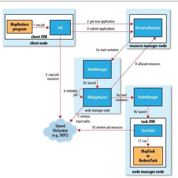
Components of the Hadoop map reduce- YARN
Before going into details of how Hadoop jobs execute, it is essential to know different components that are involved in job execution and to know an abstract view of their roles.
Client node: this node is not actually as part of the Hadoop MR framework, it is where the developers import Hadoop map reduce libraries to be able to write applications which will be later to be submitted to the Hadoop map reduce framework for the execution phase.
Resource Manager or Job Tracker: as described above, it is a daemon which will be deployed on master machine and it controls and monitors all the cluster resources and manages to distribute the workload between slave nodes. Node Manager or Task Tracker: node manager is a daemon which is
deployed on a slave node and is responsible for managing the resources inside that specific node. It creates execution container on each slave node and sends none stopping heartbeats to the resource manager to inform it about the status of the resources of each slave node. Since then, it would be possible for the node manager to decide about the job assignment to different slave nodes on the cluster.
Map reduce application master: it coordinates and manages the map and reduce jobs, sends signals to the resource manager to schedule the tasks which will be started by other node managers on a later stage.
Hadoop HDFS: is a shared Hadoop file system storage which can be used to share jobs artifacts between different components of Hadoop.
Steps of job execution in Hadoop
1. Job submission, Client interacts with code objects of the application to submit the job with the required inputs
2. Job code starts interaction with the resource manager daemon to and asks for an assignment of resources and job meta data like job ID
3. Application code then sends all the resources which later should be used by the slave nodes into a temporary HDFS storage which is shared among the cluster nodes
4. Application code then submits the job to the resource manager
5. In this phase, resource manager takes a node manager with enough re-sources and asks to for an Application Master for the submitted job
6. The chosen node manager then generates an application master
7. The generated application master then retrieve the input resources that were copied into the shared HDFS, i.e. meta data of input splits( these information were copied in step3)
8. Application manager then starts send feedback to the resource manager to ask for the required resources to be allocated to the job. The resource
manager, then selects the slave node with enough resources and replies back to the application master
9. Application master then starts containers on the chosen selected nodes to and will tell them to start a new map reduce job
10. The chosen nodes then retrieve the resources form shared HDFS.
11. The slave nodes start to handle map and reduce tasks in parallel, at the end of the reduce phase, the results will be written back into HDFS
Speed up Hadoop tasks
During the tasks execution on each slave node, the progress of that job is monitored by the related node manager. During the execution of map and reduce tasks on the slave nodes, it is possible that on slave fails or to be so slower than other slave nodes. This will slower done the entire program to be finalized. For instance if our job involves 100 map tasks which are separated between 100 slave nodes and one of the slaves goes slower than others, then the other 99 systems should be wait for the job of the 100th node to be completed. In this case Hadoop will not kill that specific slow task neither tries to fix the problem of that slow task. Instead, it starts a new task inside another machine which has a backup copy of the blocks inside. Whenever each one of the tasks completed earlier, then framework will kill the task which is still in processing in another node. And sends the data to its related destination where needed. This is called speculative execution.
The goal of speculative execution is reducing job execution time, However the cluster efficiency affecting due to duplicate tasks.
2.3.2
Oryx 2.0
Oryx 2.0 is a realization of the lambda architecture built on Apache Spark an-dApache Kafka, but with specialization for real-time large scale machine learn-ing. It is a framework for building applications, but also includes packaged, end-to-end applications for collaborative filtering, classification, regression and clustering 4.
Kafka
Kafka is a distributed, partitioned, replicated commit log service. It provides the functionality of a messaging system, but with a unique design5.
Common concepts on Kafka
1. Topics: topic is a category of messages that is preserved by kafka mes-saging queue mechanism
2. Producer: producer would be considered as a source of data that injects messages to topics
3. Consumer: consumer would be considered as a those objects which are subscribed to the topics to obtain the published messages from those topics
4. Broker: Kafka can be deployed as a cluster of servers, each of these are called a broker
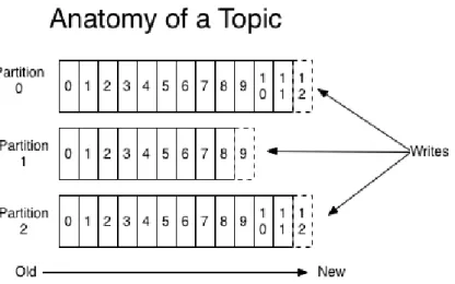
Topics
Topic is where messages are stored. The concept of Kafka topic and its parti-tions are shown in Fig.2.4. Each topic could have one or more partiparti-tions. A topic is a category or feed name to which messages are published. For each topic, the Kafka cluster maintains a partitioned log that is an ordered sequence of messages, it is immutable, which means messages are appended only into these partitions. The concept of the partition brings an important feature to the concept of topic and it is parallelism. This means that many consumers can refer to a topic at a same time, each one reading messages from different partitions.
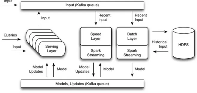
Oryx 2.0 layers
Oryx 2.0 contains three distinct layers which cooperate to each other. The architecture of Oryx 2.0 is shown in Fig.2.4
Figure 2.3: Kafka Topic and Partition
1. Batch Layer: This layer mainly works with historical data that is stored in HDFS, the computation of this layer has a very high workload and it takes a long time to be completed. For instance, hours to days. On the other hand, the result which is made by this layer is more reliable and accurate. It is made as a Spark Streaming process on a Hadoop Cluster which saves the read data from the input topic of Kafka into HDFS to be combined by the historical data and then it starts its long computation to obtain a new model, the resulted model would be saved back into HDFS. Also, it is published into Kafka Update topic to be used by the speed layer or serving layer.
2. Speed Layer:This layer is much faster than the Batch Layer, it con-sumes the new streaming data that is injected to the input topic and also, periodically gets access to the update topic to obtain the last avail-able model to be processed. The update model results of this layer will be provided in a short time; for example, in few seconds of time. It is important to know that is a memory starving process as, its computations require a lot of memory.
3. Serving layer: this layer exposed the necessary APIs to ask queries on the framework. Also, it is used to inject the primary inputs to Oryx.
makes it possible for the other three layer to communicate with each other.
Note: some of the layers can be omitted depending on the application requirements. For instance, it is possible not to deploy the Speed Layer only.
Figure 2.4: Kafka Topic and Partition
2.4
TOSCA as a DSL
TOSCA-YAML is a Domain Specific Language that is going to be more popular in cloud standard. It defines the description of components that should be automatically deployed by orchestration engines and the relationships, and dependencies between them. It is also possible to define the requirements and the capabilities that is provided by the uploaded components in TOSCA-YAML. Actually, Its intent is to improve the portability of cloud applications in the face of growing diversity in cloud environments. [27]. In another words, TOSCA is generic enough to cover a variety of scenarios and also portable between different cloud management environments [5].
In the first release of TOSCA, the community used to use XML presentation of the profile, but in TOSCA-YAML version using the YAML representation made it more Human readable, and its syntax is easier to read, maintain and
By moving from XML representation to YAML presentation of TOSCA, the main concepts of the original TOSCA remained unchanged that is TOSA-YAML is isomorphic to TOSCA version 1.0.
2.4.1
TOSCA building blocks
TOSCA metamodel uses the service template to specify cloud systems as a graph of node templates. Node templates are used to describe the components of the cloud and the relation between them. Furthermore, TOSCA provides types for the nodes and the possible relationship types between those nodes. Also, in TOSCA node and relationship types can provide the specific opera-tions which are related to the life-cycle of the mentioned components. These operations could be used by the orchestration engine to handle different pos-sible states of components. For instance, create operation will generate a new instance of the specific component, or start and stop operations are used by the orchestration engine to invoke their related scripts to be executed in order to implement the behavior of that component.
The orchestration engine uses the lifecycle operations mentioned above to pro-cess that specific service template. Also it uses the determined relationships between different components to decide about the order on which those com-ponents should be instantiated. As an example, in case of Hadoop MR, it is important to start the Node Manager and Name Node before starting of Slave nodes. Because, it is the Name Node which contains the meta-data of the save nodes. As another example, it is possible that an application of Hadoop MR interacts with a relational database like MySQL. In this case, it is important that orchestration engine first initializes the database by create operations and then start it with the start operation and then create and start the Hadoop application which contains the information to connect to that instance of database.
TOSCA standard, provides a number of base types, both for nodes and the relationship between those nodes, like compute node, database node and etc. For example, in case of Hadoop MR, there are two kinds of nodes, master nodes and slave nodes which interact with each other, we can define this nodes as compute nodes in TOSCA and also define their relations by using TOSCA
relationship type. Also, as for the MySQL database used by the Hadoop MR application, we can define a mapping to database node in TOSCA.
2.4.2
TOSCA Artifacts
In this section, we want to specify the artifacts related to TOSCA in terms generalities [10]:
1. TOSCA-YAML service template: This is a YAML format blueprint that specifies the TOSCA recipe of the cloud application to be deployed by the orchestration engine. Usually, it contains a service template with node templates and their relationships inside.
2. TOSCA processor: It is a general concept which its aim is to validate a TOSCA-YAML specification, or to convert it into a visual diagram for better understanding of the cloud concepts and their relations.
3. TOSCA orchestrator: it is a specific concept of TOSCA processor which contains a generic workflow engine that compiles the TOSCA-YAML recipe to deploy the application i.e. Hadoop MR on the cloud.
4. TOSCA archive: As building a TOSCA recipe for a specific application demands the knowledge of the components of that applications and also their relations, then building a TOSCA-YAML blueprint is not an easy task. So, it seems to be prudent to build such a repository of TOSCA-YAML recipes to be used by the orchestrations engines.
2.4.3
TOSCA-YAML Terms
The following terms which are described in Table 2.1 are common in every TOSCA-YAML blueprint and will be useful when we go more deep in to the details through this document:
The example blueprint6 that is shown below describes the deployment of a
two tier application on cloud of two Compute Nodes, each one with its own properties and capabilities. TOSCA orchestration engines select the best node with respect to the above specifications defined in the blueprint.
http://docs.oasis-open.org/tosca/TOSCA-Simple-Profile-Node Template Node Template describes a software compo-nent, it has a Node Type that specifies the different features related to that specific node type. It is one of the building blocks of the Topology Template. Node Types can be de-fined separately as a template to be reused in future purposes.
Relationship Template Relationship Template defines the relation-ship between Node Templates. Also, rela-tionship templates have type to define their different features. As like Node Templates also, they can be reused for future require-ments.
Topology Template Topology Template consist of Node Tem-plates and Relationship TemTem-plates that de-fines the relation between those nodes. In other words, it describes the structure of the Service Template that can be used by the orchestrator to instantiate a model form it. Service Template Each Service Template, allows to define a
Topology Template, TOSCA Types and their constraints and their inputs and outputs.
Table 2.1: TOSCA-YAML Common Terms
At the top,tosca_definitions_version key name indicate the Service Tem-plate to validate the definitions and types in the recipe. As currently there is not any orchestration engine that completely follow the Service Template of TOSCA-YAML, it is also possible to use the import key word to use other Service Templates like Service Templates available by Cloudify Orchestration engine.
Going back to the bottom of the example, inside my server, capabilities, the host, includes properties that developer is expected as a need when the appli-cation is going to be run on that server. For example, number of CPUs, RAM
size, etc. on the other side OS capability defines the features of the operating system that the server should have.
On the top inputs section inside the Topology Template inputs can be used to assign values to properties of Node Template also, it is possible to assign constrains to each input; for instance, in this example the number of CPUs can be chosen between 1 and 4.
tosca_definitions_version: tosca_simple_yaml_1_0 topology_template: inputs: cpus: constraints: - valid_values: [ 1, 2, 4, 8 ] node_templates: wordpress: type: tosca.nodes.WebApplication.WordPress properties:
context_root: { get_input: context_root }
apache:
type: tosca.nodes.WebServer.Apache properties:
# omitted here for brevity requirements:
- host: web_server
web_server:
type: tosca.nodes.Compute capabilities:
my_db:
type: tosca.nodes.Database.MySQL properties:
name: { get_input: database_name } user: { get_input: database_user } artifacts: db_content: file: files/my_db_content.txt type: tosca.artifacts.File requirements: - host: mysql mysql: type: tosca.nodes.DBMS.MySQL properties:
root_password: { get_input: my_mysql_rootpw } port: { get_input: my_mysql_port }
outputs: server_ip:
These inputs will be asked by the orchestration engine to be filled during the deploy time. In DICE one of our goals is to provide all the required information needed for the deployment on DDSM layer and then generate the TOSCA-YAML recipe based on that. The values of the inputs should be assigned during model to text transformation by the given information of the desired model of DDSM layer to be transferred to TOSCA-YAML through XText model to text transformation.
On the other part, by outputs section values can be obtained from the attributes of the node template to be used elsewhere.