Leaf community: Control of an AC microgrid
Pietro Ferraro
Thesis supervisor: prof. ing. Alberto Landi
Thesis supervisor: dott. ing. Emanuele Crisostomi
Abstract
Microgridscan be considered the building block and the backbone of the new way of thinking the electrical grid, the smart grid. Integration of control theory, information technology and electronic power plays an important role in closing the gap with this new paradigm which is considered an important step towards integration of renewable sources of energy, new economic opportunities and an overall safer and more efficient electric distribution net.
This thesis has been developed in cooperation with the Loccioni group. The contribution of this thesis are threefold: (i) a realistic model of their microgrid was implemented in a Matlab/Simulink environment; (ii) a control system was designed to achieve stability of the whole system and to obtain plug and play inverters, that can work without central controllers; (iii) the developed algorithms were implemented in a PLC environment.
The solutions implemented within the thesis work are being currently implemented in the real microgrid at Loccioni.
Introduction
The electric power system enterprise has witnessed many recent developments that not only revived inter-est in research and development but also resulted in significant socio-economic benefits to the community at large. The very protagonist of this new paradigm is the so called smart grid. The concept was given different names, such as intelligent grid, grid wise, EPRI’s Intelligrid, and others. While defining the term may initially appear to be illusive, there is almost unanimous agreement that the smart grid is a dynamically interactive real-time infrastructure concept. A possible way of defining it may be [1]:
“The smart grid is a suite of information based applications made possible by increased automation of the electricity grid, as well as the underlying automation itself; this suite of technologies integrates the behaviour and actions of all connected supplies and loads through dispersed communication capabilities to deliver sustainable, economic and secure power supplies.”
Microgrids and its derived forms can be considered and exploited as the main building block of the smart grid: it can be defined as an electrical entity that facilitates high depth of penetretion of DER units and relies on ICTs and advanced control/protection strategies. Roughly speaking a microgrid is a cluster of DERs and controllable loads that can work, both in grid connected mode and in stand alone mode (islanded from now on), able to conduct policies of Demand and Response with other microgrids.
Loccioni micro grid
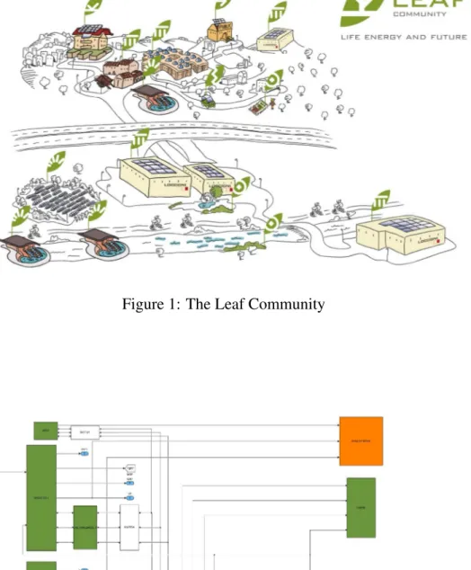
Figure 1 shows the Leaf Community, an example of microgrid that is being developed by the Loccioni group at their headquarter, that comprehends two hydroelectric plants, four fields of solar panels and, one storage battery. This work has been developed in cooperation with them and has dealt with the following points:
• Analysis of state of the art researches in the micro grids field
• Development of a Matlab/Simulink model of the Loccioni micro grid.
• Analysis and simulation of real time control algorithms for islanded micro grids • Gap analysis of an industrial inverter for micro grid-ready control
• Development of simulated algorithms in a PLC environment
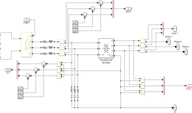
Figure 2 shows the Simulink model that has been developed while figure 3 shows the Simulink model of the realized inverters. Simulations described in the following sections have been carried out on such a model.
Inverters control
The main element that allows different sources of energy to be combined togheter is the power inverter: an electical device able to transform the input voltage into a sine wave with controllable frequency and amplitude. The inverter represents the backbone of the integration of distributed energy resources. With-out it there could be no microgrid. In figure 4 it is shown the circuital model of a single phase inverter: the
Figure 1: The Leaf Community
Figure 3: Inverter model
controlled inputs are represented by the signal that command the switches u, while the measured outputs are represented by the current iL that flows through the inductor L and the voltage between the capacity
Cand the ground, v0. The output current, iois treated as an external disturbance.
Figure 4: Power stage of a single phase inverter
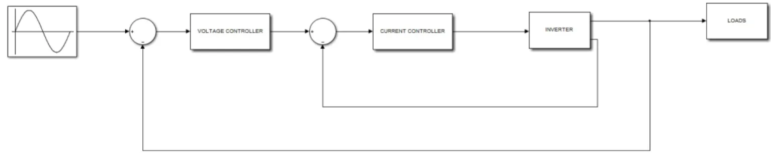
A Voltage Source Inverter (VSI) is an inverter in which the output voltage v0has to track a reference
signal. This is in general accomplished by using two control loops: a fast inner loop that regulates the current iL and a slower outer loop that regulates the voltage v0. Figure 5 shows the block diagram of this
control strategy. In order to obtain a good tracking performance of the reference signal a comparison between PID controllers and internal model based controllers, called Proportional Resonant (PR), has
been made. The PIDs were tuned by using a genetic algorithm while the PRs were tuned by using the root locus method. The tracking performance is shown in figure 6. The genetic algorithm has run for over ten thousand epochs.
For the good tracking performance and the simplicity of the tuning, the PR controller was chosen as control method for the inverters employed.
Figure 5: Control scheme of a VSI inverter
Control architectures
The control strategy has to guarantee the following features for an islanded microgrid
• Inverters should share the load in a controllable way
• The control based on local measures should grant global stability
• The control has to maintain the desired frequency, phase and amplitude on the line.
The two main control architectures that obtain the previous points are the master-slave and the hier-archical one: the first one has a simple structure and control system(one VSI many CSIs) but presents some serious drawbacks for what regards stability, robustness and cost, the second one on the other hand, despite being stable, cost efficient and robust has to employ a complex multi-layered control structure (many VSIs connected in parallel). The previous reasons plus the will of designing a plug-and-play system has led to choose a hierarchical distributed control system [2].
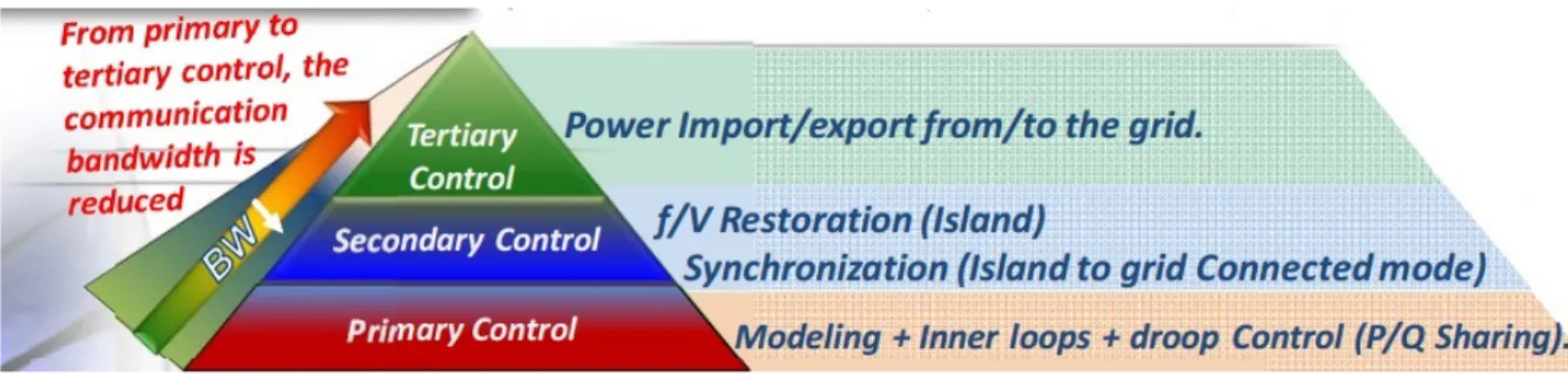
Figure 7 shows a compact scheme of the system. As previously stated the microgrid is composed exclusively by VSIs and each layer of the control architecture deals with specific issues.
• The primary control grants global stability, based on local measures and allows to control the power injected by each inverter into the grid
(a)
(b)
Figure 6: (a) PID tracking and (b) PR tracking of a sine wave
• The secondary control keeps frequency and voltage of the grid to the desired value and allows the resynchronization with the main grid.
Figure 7: The hierarchical architecture
• The tertiary control deals with the import/export of power from and to the microgrid and has not been investigated in this work.
Primary and secondary control
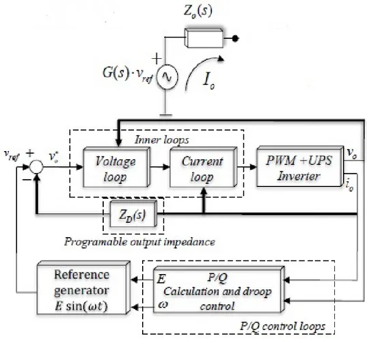
The structure of the primary control is shown in figure 8. There are four controllers: the current and voltage control, also called inner loops, the virtual impedance and the droop control.
Droop control Due to the load effect it is not possible to control the power injected into the grid by each inverter. Droop control solves this problem by implementing the following laws [3][5]
Ei= E∗− niPi, (1a)
ωi= ω∗+ miQi (1b)
Ei= E∗− niQi, (2a)
ωi= ω∗− miPi. (2b)
The (1a-1b) are employed if the output impedances of the inverters are purely resistive, while the (2a-2b) if the impedances are purely inductive. This allows the user to control the active and reactive power injected, by changing the droop coefficients niand mi.
There are two drawbacks in the droop control:
• the drooping it introduces on frequency and amplitude, that will go to different values than ω∗and E∗for Pi6= 0 and Qi6= 0,
• there could be mismatches in the power sharing due to inherent limitations of the control law [4][5]. These effects will be compensated by the secondary control.
Virtual impedance We have seen in (1a-1b) and (2a-2b) that the droop control changes with respect to the output impedance of the inverter. This quantity generally depends on parasitic parameters that might be hard to measure(the resistance rL in figure 4 for example). For these reasons the virtual impedance is
introduced[6]: its purpose is to force the output impedance to be totally resistive or inductive in order to improve the performance of the droop control and to reduce the dependencies from parasitic quantities.
Figure 8: Primary control overview
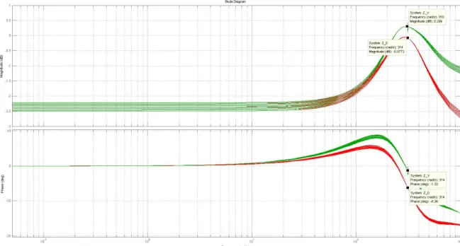
Figure 9 shows how this is performed (the impedance values are calculated for different rL values): the
red line represents the output impedance before the virtual impedance is introduced while the green line shows the effects of its introduction. In the particular case shown, the goal was to bring the phase nearer to 0 degrees at 50 Hz.
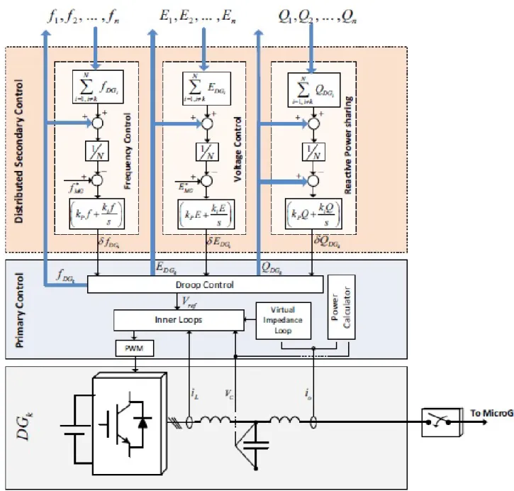
Secondary control In the previous paragraphs it was pointed out that another control loop is required in order to restore the values of frequency and amplitude and to equalize mismatches in power sharing. This can be accomplished both in a centralized and in a distributed way but, since there is the will of designing a plug and play device, the distributed architecture was chosen. Figure 10 shows the strategy employed[4]; in this particular case it was supposed that the primary control fails to share accurately the reactive power. In the Simulations section the performances of the controllers described in the previous sections are analyzed.
Figure 9: Virtual impedance effect
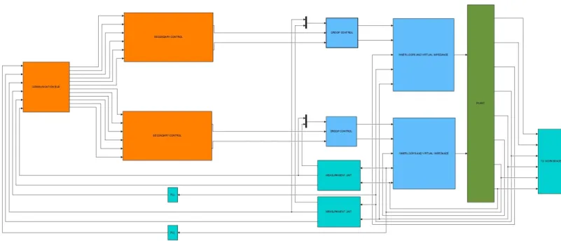
Simulink model of the microgrid and simulations
Figure 11 shows the simulink model realized for the Loccioni group with the control system designed: the green block represents the model of figure 2 while the blue and the orange blocks represent respectively the primary and the secondary control. In order to model the inverters shown in figure 3 the SimPower library was widely used: every inverter is controlled by a PWM signal and has a different line impedance.
The inverters TDE AFE are connected to the DC side with a storage system Samsung of 227 kW. The DC voltage side is set to 1000 V and the loads considered are respectively 178 kW and 232 kW. In absence of further informations a power factor of 0.9 was supposed. The numerical values used to model these inverters can be found in the thesis.
The simulations of the two possible main scenarios have been carried out:
• Two inverters in island mode start with a phase difference of π. An abrupt load shift occurs at 35 seconds.
• The two inverters are initially connected to the main grid. At 5 seconds an islanding event occurs and they disconnect switching stand-alone mode. At 35 seconds the two inverters resynchronize with the main grid and are ready to switch to grid-connected mode again.
The plots of the data obtained from the aforementioned simulations have been omitted in this report (they can be found in the presentation and in the original thesis work). From them it is possible to infer the following conclusions:
Figure 10: Distributed control scheme
• The voltage drop on the transformer is too high and, since the controlled variable is the capacity voltage, it is not possible with the current inverters to realize a distributed control system able to restore the amplitude of the pcc voltage to an acceptable value. This issue can be solved by increasing the switching frequency of the inverter (this would make the needed transformer and the consequent voltage drop, smaller) or by placing sensors after the secondary terminal of the transformer and adding another control loop. Switching to a centralized secondary controller might be a solution as well but this would make the system a lot more critical.
Figure 11: Inverter model
the lack of sensors for the transformer current.
• It is not possible at the time being to realize any secondary control due to the lack of sensors for the frequency and amplitude of each inverter voltage.
References
[1] Mohamed E. El-hawary, Department of Electrical and Computer Engineering, Dalhousie University, Halifax, Nova Scotia, Canada Consulting Editor, Electric Power Components and Systems Journal The Smart Grid—State-of-the-art and Future Trends05 feb 2014.
[2] Guerrero J.M. Hierarchical Control of Droop-Controlled AC and DC Microgrids. A General Ap-proach Toward Standardization
[3] K. De Brabandere, B. Bolsens, J. Van den Keybus, A. Woyte, J. Driesen and R. Belmans K.U.Leuven ESAT / ELECTA A Voltage and Frequency Droop Control Method for Parallel Inverters
[4] Qobad Shafiee, Juan C. Vasquez, and Josep M. Guerrero A Distributed Secondary Control for Is-landed MicroGrids. A Networked Control Systems Approach
[5] Qing Chang Zhong Tomas Hornik Wiley, IEEE press Control Power Inverters in renewable energy and smart grid grid integration
[6] Guerrero,J.M. Luis Garc´ıa de Vicu˜na, Jos´e Matas, Miguel Castilla, and Jaume Miret Output Impedance Design of Parallel-Connected UPS Inverters With Wireless Load-Sharing Control