P
OLITECNICO DI
M
ILANO
S
CHOOL OFI
NDUSTRIAL ANDI
NFORMATIONE
NGINEERINGM
ASTER OFS
CIENCEC
OURSE INA
ERONAUTICALE
NGINEERINGConceptual Design of
Hybrid-Electric Aircraft
S
UPERVISOR: Prof. Lorenzo Trainelli
C
O-S
UPERVISORS:
•
Prof. Carlo E.D. Riboldi
•
Prof. Alberto Rolando
N
ICCOLÒR
OSSIID - 852348
Contents
1 Introduction 1
2 Technology Survey 3
2.1 Batteries and Energy Storage systems . . . 3
2.1.1 Li-ion and Li-poly batteries . . . 4
2.1.2 Structural batteries . . . 6
2.1.3 Li-air batteries . . . 7
2.1.4 Li-S batteries . . . 8
2.2 Electric Motors and Systems . . . 9
2.3 Power Generators . . . 12 2.3.1 Reciprocating engines . . . 13 2.3.2 Turboshaft engines . . . 14 2.4 Review of Aircraft . . . 15 2.4.1 Existing airplanes . . . 15 2.4.2 Ongoing projects . . . 17 2.4.3 Conceptual projects . . . 18
3 Electric and Hybrid-Electric Aircraft Sizing Approaches 21 3.1 Battery Mass Sizing . . . 21
3.2 Hybrid-Electric Design Approach . . . 24
3.2.1 Degrees of Hybridization . . . 24
3.2.2 Hybrid propulsion architectures . . . 27
3.3 Design Examples . . . 29
3.3.1 Ultralight aircraft . . . 29
3.3.2 Commuter aircraft . . . 31
3.3.3 Airliner . . . 33
4 Design and Simulation Procedure 35 4.1 Working Assumptions . . . 35
4.2 Sizing Procedure . . . 37
4.2.1 Aerodynamic data estimation . . . 38
4.2.2 Empty mass estimation . . . 39
4.2.3 Performance estimation . . . 39
4.2.4 Generator model . . . 42
4.2.5 Motor and battery sizing . . . 46
4.2.6 Fuel mass sizing . . . 47
4.3 Flight Simulation . . . 49
4.3.1 Flight phase simulation . . . 50
4.3.2 Flight envelope simulation . . . 52
4.3.3 Flight phase strategies . . . 53
4.3.4 Generator control strategies . . . 54
4.4 Implementation of Hyperion Program . . . . 54
4.4.1 Input data . . . 54
4.4.2 Program overview . . . 55
5 Results, Validation and Design Examples 57 5.1 Results and Validation . . . 57
5.1.1 General aviation . . . 58 5.1.2 Micro feeder . . . 60 5.1.3 Commuter . . . 60 5.1.4 Large regional . . . 61 5.2 Design Examples . . . 61 5.2.1 General aviation . . . 61 5.2.2 Micro feeder . . . 66 5.2.3 Commuter . . . 69 5.2.4 Large regional . . . 72
6 Parametric Analysis and Sensitivity Studies 73 6.1 Procedure Overview . . . 73
6.2 Case Studies . . . 74
6.2.1 Hybrid-Electric 8-seater . . . 74
6.2.2 All-Electric 8-seater . . . 85
6.2.3 Hybrid Regional Aircraft . . . 90
List of Figures
2.1 Ragone diagram displaying available technologies in 2008, from[2]. . . 4
2.2 Available and predicted specific power (left) and energy (right) trends for Li-ion based cells for HEVs and EVs, from[6]. . . 5
2.3 Schematic of the practical realization of a smart structure with thin-film Lithium cells in CFRP laminate with traditional vacuum bag technique, from[11]. . . 6
2.4 Schematic of 3D CFE+SPE battery, from [10]. . . 7
2.5 Schematic of a Lithium-air battery, from[6]. . . 8
2.6 Schematics of Lithium-Sulfur battery layout, from[6]. . . 8
2.7 Specific energy of different batteries resulting from combinations of dif-ferent positive and negative electrodes, from[2]. . . 9
2.8 SP260D motor during testing phase (left) and motor optimization con-cept (right), from[20]. . . 10
2.9 Schematic of a high-temperature superconducting motor, from[21]. . . 11
2.10 Schematic of Silent Advanced Fan utilizing Electrical power (SAFE), from [23]. . . 12
2.11 Relative Ragone diagram for power systems, from[2]. . . 13
2.12 Sensitivity of HE effectiveness on fuel consumption - power relationship (left) and on NOX oxides (right), from[26]. . . 14
2.13 Pipistrel Alpha Electro, from[47]. . . 15
2.14 Airbus E-Fan, from[49]. . . 15
2.15 Solar Impulse 2, from[52]. . . 16
2.16 Pipistrel HY-4, from[53]. . . 16
2.17 Extra 330LE, from[45]. . . 17
2.18 Pipistrel Panthera conventional version, from[55]. . . 17
2.19 NASA X-57 Maxwell concept, from[57]. . . 18
2.20 Airbus E-Fan X concept (left) and schematic (right), from[58]. . . 18
2.21 Flynk aircraft, from[27]. . . 19
2.22 Hybris aircraft, from[60]. . . 19
2.23 Flybrid aircraft, from[61]. . . 20
2.24 SUGAR High (left) and SUGAR Volt (right) concepts, from[30]. . . 20
3.1 Complete flowchart of all-electric aircraft sizing, from[31]. . . 23
3.2 Trends of possible aircraft hybrid architectures at different installed power, from[25]. . . 26
3.4 Classification of possible architectures for hybrid-electric vehicles, from
[35]. . . 27
3.5 Electric aircraft propulsion architecture classifications, from[36]. . . 28
3.6 Standard SONG ultralight aircraft, from[37]. . . 29
3.7 Mission profiles used to compare SOUL aircraft with conventional solu-tion, from[37]. . . 30
3.8 Proposed architectures for PACIFYC aircraft, from[7]. . . 31
3.9 Market analysis for medium-range European airliner, from[24]. . . 33
3.10 Overview on Ce-Liner, from[24]. . . 34
4.1 Considered mission profile. . . 37
4.2 Mass-Power regression for electric motors and thermal engines. . . 48
4.3 Hyperion program scheme. . . . 56
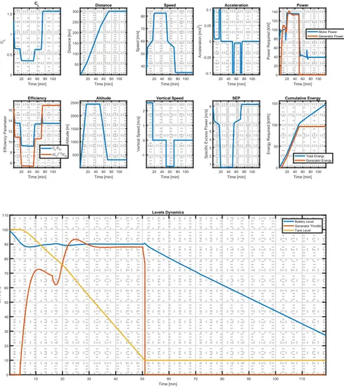
5.1 Variables evolution for Panthera Hybrid simulated aircraft. . . 59
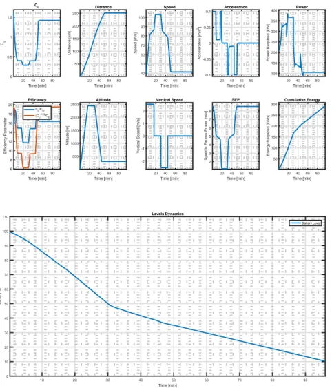
5.2 Parameters evolution for general aviation all-electric design example. . . 63
5.3 Parameters evolution for general aviation hybrid-electric design example. 64 5.4 Parameters evolution for micro feeder all-electric design example. . . 66
5.5 Parameters evolution for micro feeder hybrid-electric design example. . 67
5.6 Parameters evolution for commuter steady charging design example. . . 69
5.7 Parameters evolution for commuter cyclic charging design example. . . . 70
5.8 Levels evolution comparison for large regional design examples between steady (above) and cyclic (below) charging. . . 72
6.1 Hybrid 8-seater sensitivity on aircraft range and battery specific energy. 75 6.2 Hybrid 8-seater sensitivity on battery specific power and specific energy of close future batteries. . . 76
6.3 Hybrid 8-seater sensitivity on battery specific power and specific energy of long time-span batteries. . . 77
6.4 Hybrid 8-seater sensitivity on generator power-to-weight ratio and pres-sure ratio. . . 78
6.5 Hybrid 8-seater sensitivity on climb speed and battery specific energy. . 79
6.6 Hybrid 8-seater sensitivity on rate of climb and battery specific energy. . 80
6.7 Hybrid 8-seater sensitivity on cruise speed and battery specific energy. . 81
6.8 Hybrid 8-seater sensitivity on cruise altitude and battery specific energy. 82 6.9 Hybrid 8-seater sensitivity on final state of charge and battery specific energy. . . 83
6.10 Hybrid 8-seater sensitivity on final state of charge and battery specific power. . . 84
6.11 Electric 8-seater sensitivity on battery specific power and specific energy of close future batteries. . . 85
6.12 Electric 8-seater sensitivity on battery specific power and specific energy of long time-span batteries. . . 86
6.13 Electric 8-seater sensitivity on range and battery specific energy. . . 87
6.14 Electric 8-seater sensitivity on cruise altitude and battery specific energy. 88 6.15 Electric 8-seater sensitivity on rate of climb and battery specific energy. . 89
6.16 Hybrid regional aircraft sensitivity on battery specific power and specific energy. . . 90
6.17 Hybrid regional aircraft sensitivity on range and battery specific energy. 91 6.18 Hybrid regional aircraft sensitivity on number of passengers and battery
specific energy. . . 92
6.19 Hybrid regional aircraft sensitivity on cruise speed and battery specific
energy. . . 93
6.20 Hybrid regional aircraft sensitivity on cruise speed and battery specific
List of Tables
2.1 Pipistrel Alpha Electro specifications, from[48]. . . 15
2.2 Airbus E-Fan specifications, from[50]. . . 15
2.3 Solar Impulse 2 specifications, from[52]. . . 16
2.4 Pipistrel HY-4, from[53]. . . 16
2.5 Extra 330LE data, from[45]. . . 17
2.6 Pipistrel Panthera expected specifications, from[56]. . . 17
2.7 NASA X-57 Maxwell available specifications, from[57]. . . 18
2.8 Flynk specifications, from[27]. . . 19
2.9 Hybris specifications, from[28]. . . 19
2.10 Flybrid specifications, from[29]. . . 20
3.1 SOUL aircraft properties, from[37]. . . 29
3.2 SOUL performance for mission profile 1, from[37]. . . 30
3.3 SOUL performance for mission profile 2, from[37]. . . 30
3.4 PACIFYC study requirements, from[7]. . . 31
3.5 Properties and electrical component performance for PACIFYC aircraft, from[7]. . . 32
3.6 Comparison between present state-of-art, reference 2030 conventional aircraft and the two best PACIFYC architectures, from[7]. . . 32
3.7 Comparison between Ce-Liner and reference Boeing 787-3+ version, from [24]. . . 34
4.1 Correlation coefficients for parasite area, from[38]. . . 39
4.2 Statistical regression values relating empty weight and wetted surface to takeoff weight, from[38]. . . 39
4.3 Experimental values used for turboshaft model, from[40]. . . 43
4.4 Electric motors population. . . 48
4.5 Set of simulation variables. . . 49
5.1 Input data for validation processes. . . 57
5.2 Results of general aviation aircraft validation. . . 58
5.3 Results of micro feeder aircraft validation. . . 60
5.4 Results of commuter aircraft validation. . . 60
5.5 Results of large regional aircraft validation. . . 61
5.6 Common input values for general aviation all-electric and hybrid-electric design examples. . . 62
5.8 Common input values for micro feeder all-electric and hybrid-electric
de-sign examples. . . 65
5.9 Results of micro feeder design examples. . . 65
5.10 Comparison between hybrid-electric micro feeder variants. . . 67
5.11 Input values for commuter hybrid-electric design examples. . . 68
5.12 Results of commuter design examples. . . 68
5.13 Common input values for large regional hybrid-electric design examples. 71 5.14 Results of large regional design examples. . . 71
Sommario
Un aumento nell’interesse su applicazioni elettriche alla propulsione sia per veicoli di terra che per aeroplani è stato osservato nel corso degli ultimi anni, grazie a batterie e motori elettrici più affidabili e performanti. La propulsione elettrica per applicazioni aeronautiche rappresenta tuttora una porzione ridotta nell’aviazione corrente, a causa delle penalità in termini di peso delle batterie e a causa della scarsità di tecniche di pro-gettazione adeguate. Il presente lavoro si focalizza sullo stabilire una procedura gen-erale per la progettazione concettuale di un velivolo completamente elettrico o ibrido-serie e di simularne il profilo di missione per valutare i consumi energetici, per as-sicurare la massima accuratezza. Un programma Matlab™chiamato Hyperion è stato sviluppato e validato utilizzando velivoli esistenti come riferimento, considerando un caso limite di un velivolo convenzionale simulato. La procedura considerata si basa sull’assunzione di un velivolo ad elica propulso da motori elettrici alimentati da batterie, eventualmente caricate da un generatore nel caso di velivolo ibrido. Il dimensiona-mento preliminare è condotto considerando potenze richieste ed energie stimate, men-tre l’effettiva performance è simulata step-by-step con una procedura iterativa, basata sul livello finale di carica delle batterie e, se presente, del carburante nei serbatoi. Studi di letteratura e analisi tecnologiche sono stati effettuati per stabilire una base di lavoro solida, che è poi utilizzata in un ampio set di studi parametrici per valutare la sensitività di parametri chiave come raggio, performance di batteria, velocità e quota di crociera, su parametri del velivolo quali massa al decollo, di batterie e carburante, superficie alare, potenze richieste e grado di ibridizzazione in energia.
Parole chiave: Aereo Elettrico, Velivolo Ibrido-Elettrico, Mahepa, Simulazione di
Volo, Progetto di Velivolo Ibrido-Elettrico, Sensitività su Progetto di Velivolo, Programma Hyperion.
Abstract
An increased focus on electric applications to propulsion for both ground vehicles and airplanes has been observed in recent years, thanks to more reliable and more perform-ing batteries and electric motors. Electric propulsion for aircraft applications is still rep-resenting a very small portion of current standard aviation due to large mass penalties of batteries and due to rather unexplored design procedures. The present work focuses on establishing a general procedure to design an all-electric and serial hybrid-electric aircraft from a conceptual point of view and to simulate their flight profile to assess energy consumption to ensure the highest accuracy possible. A Matlab™code named
Hyperionwas developed and validated using existing aircraft as a reference, consider-ing the limit case of a simulated conventional aircraft. The considered procedure is based on the assumption of a propeller-driven aircraft powered by electric motors fed by batteries, which are, in case of a hybrid airplane, charged by a generator. Prelim-inary aircraft sizing is conducted by means of required power and estimated required energy, and actual performance is simulated step by step with an iterative procedure based on final state of charge and fuel tank, if present, levels. Literature studies and technology survey are carried out to establish a robust working base, that is consid-ered in a wide set of parametric studies to assess sensitivity of key parameters such as battery performance, cruise speed and altitude, aircraft range among others, on param-eters as takeoff, battery and fuel mass, wing surface, motor power and energy degree of hybridization.
Key words: Electric Aircraft, Hybrid-Electric Aircraft, Mahepa, Aircraft Flight
Sim-ulation, Hybrid-Electric Aircraft Design, Aircraft Design Parametric Analysis, Hyperion Program.
Chapter 1
Introduction
The field of aviation is historically rich of innovation and always had a pioneering role in modern society: as airplanes started to connect distant places in a safer, faster and more reliable way, more and more people started to travel; the challenges that aeronautical companies had to face changed in time, and shaped the path followed
by aviation itself. One of the biggest challenges of the 21st century is to face climate
change, a challenge that can be faced only through the reduction of the environmental impact of our machines, airplanes included. The reduction of the environmental impact of airplanes has been a secondary effect, being the main one to reduce the amount of fuel used during a standard mission in order to reduce both weight of the aircraft and expenses for a company.
Current European plans[1] for future aviation involve the reduction of both noise
and pollutant emissions from airplanes to grant a sustainable growth of this field, in-creasing safety, innovation and air transport effectiveness, allowing to more and more people to travel quickly within the European boundaries. The solutions to this chal-lenging task are to be found both in the way that airplanes are used and designed: this latter field includes both the improvement of existing technologies, mainly for airliners and large aircraft, and the creation of new technologies, which is the focus of this work. One of the answers to the needs of the future European aviation is the MAHEPA
project, namely Modular Approach to Hybrid-Electric Propulsion Architecture[41], which
is a 4-years project devoted to establish a milestone in European aviation in terms of an
Electric Revolution: the task is to develop and test the best technologies for present and future hybrid-electric and all-electric aviation, by means of finding the most promising solutions in terms of energy storage and power generation, developing new ways of flying the new aircraft and also how to design it. This latter topic, the design of hybrid-electric and all-hybrid-electric airplanes is the target of this work: we will focus on establishing a design procedure that will allow to size an all-electric or hybrid-electric aircraft by considering all the potential differences with the traditional techniques used with fuel-based airplanes and involving high-performance computational techniques in order to have the most accurate solution possible.
The present work starts with a survey on available technologies and relative trends, discussed in Chapter 2, that are focused on:
• Electric motors: as an important difference with standard propulsive systems, and the key component to grant high overall flexibility;
• Generators: a review on thermal engines and possible fuel-saving improvement;
• Electric aircraft: existing electric and/or hybrid-electric airplanes, ongoing projects
and conceptual studies.
A brief analysis on design methods proposed by the literature is discussed in Chapter 3 to provide a general basis of sizing procedures for electric airplanes; a general hybrid-electric sizing procedure is yet unavailable, thus a view on possible architectures is presented, and may be summarized as:
• Series hybrid: where electric motors drive propellers and thermal engines provide energy to batteries;
• Parallel hybrid: where both electric motors and thermal engines are mechanically connected to propellers;
• Series/parallel hybrid: as for parallel case, but thermal engines are also connected
to a generator to provide energy to batteries;
• Partial hybrid: combinations that may vary case by case.
Chapter 4 deals with the description of the selected sizing procedure: starting with
basic hypotheses, a general procedure for all-electric or turboelectric/serial hybrid
air-craft design is presented, involving a preliminary phase conducted through statistical regression data and then an iterative simulation of the overall mission profile to have a realistic estimation of needed power and energy.
Procedure is implemented in a Matlab™program named Hyperion and results are provided in Chapter 5; relevant physical quantities are visualized and their time evolu-tion is discussed. A validaevolu-tion process is conducted and airplane design examples are presented and discussed, by analyzing four main aircraft classes:
• General aviation aircraft;
• Micro feeders, with 8-9 passengers;
• Commuters, with a maximum of 19 passengers; • Regional aircraft, up to 80 passengers.
A parametric analysis is conducted in Chapter 6, where a description of the proce-dure is presented and the sensitivity on some relevant parameters is investigated using test aircraft obtained before. The aim is to study the impact of parameters as battery data or generator power-to-weight ratio on key aircraft ones such as takeoff weight or battery and fuel mass.
Work ends in Chapter 7, where a summary about what has been observed by lit-erature and what has been obtained in previous chapters is presented, considering a critical discussion of overall results as a starting point for future work in this exciting and promising aviation field.
Chapter 2
Technology Survey
As European policies strive towards greener aviation, the key element still lies in available technology which is rapidly evolving as the market opens. In this section available technologies in terms of batteries, electric motors and generators will be in-vestigated, with a particular focus on forecasts for the next two-three decades, some of the current projects and trends predicted by companies. Aircraft examples will be presented as well as concepts and projects under development by the industry.
2.1
Batteries and Energy Storage systems
Energy storage is the first aspect to consider while analyzing the differences with conventional airplanes: as standard aviation fuel is characterized by very high energy
density1, around 12000− 13000 Wh kg−1, batteries are generally much less dense in
terms of energy and also introduce the concept of specific power. Conventional thermal engines need a certain fuel flow rate to the combustion chamber, regardless of the kind of engine and thermal cycle: what is needed to produce mechanical power is derived from combustion; the flow rate is provided by a pumping system, which design is con-ducted with high flexibility, since the size is not forced by tanks size. The same pumping system could be used on tanks characterized by different internal volume, as the main constraint is given by the flow rate that has to be provided to the engines; this is not true for batteries: in this case we both have requirements in terms of energy, as for fuel, and also on power, since storage and delivery are not decoupled as for conventional systems.
Batteries and other systems hence must be able to meet both power density and energy density requirements, as well as they must be able to show high convenience
from an economical and ecological point of view [2]; in this subsection the first two
aspects will be investigated by comparing different technologies, since cost and envi-ronmental impact are still subjected to a too high uncertainty to be treated in a general
way. Technologies are compared using the Ragone diagram[3], where the relationship
between specific power and energy (at cell level in case of batteries) is shown in a
log-1Low Heat Value (LHV) of aviation kerosene is around 43
−44 MJ kg−1; in this work the unit for energy
will be Wh, since it is the widest used in the battery field: the reader simply has to keep in mind that 1 J
log plot to visualize an optimal working region where both parameters are sufficiently
high. A general way to model energy storage devices (ESD) is presented in[4], where
a generic ESD is modeled as a RL circuit, with a voltage source as a function of battery charge, an ideal resistor and an ideal inductor; this model is well beyond the scope of this work, but it allows to model the battery from a mathematical point of view through
an empirical estimation of circuit coefficients, and to eventually visualize the Wsp- Esp
relationship for a given technology.
2.1.1
Li-ion and Li-poly batteries
Lithium-ion and Lithium-polymers batteries are the most common batteries due to very high performance compared to other technologies available on the market: as in figure 2.1 we can observe that Li-ion batteries grant the highest flexibility to be either used as capacitors, with a high power - low energy setting, and as batteries, with high energy and high to medium power; Li-poly technology shares the same kind of perfor-mance in this latter case.
Figure 2.1: Ragone diagram displaying available technologies in 2008, from[2].
Lithium battery performance is determined by materials used as electrodes[2] [5]:
state-of-art batteries are equipped with Lithium metal oxides (the most commonly used are based on Cobalt and Manganese) as positive electrodes and graphite as a negative
electrode, with theoretical specific energies limited at a maximum value of 300 Wh kg−1
airplanes2. We can consider available battery data for Tesla Model S supercar to ana-lyze Li-ion ESD performance: considering the P85 model, the battery has a maximum continuous power output of 311 kW and a total stored energy of 85 kWh, with a total
mass of 540 kg[42]; specific parameters are thus around 575 W kg−1and 157 Wh kg−1.
Continental[6] shows that the state-of-art Li-ion batteries based on LiFePO4
cath-ode, with a theoretical specific energy of around 350 Wh kg−1at 3.2 V are still providing
rather insufficient performance for long range vehicle applications, while future
batter-ies, based on LiMnPO4, LiCoPO4 and LiNiPO4 cathodes could reach theoretical values
of 450 Wh kg−1at 4.1 V, 520 Wh kg−1at 4.8 V and 600 Wh kg−1at 5.1 V respectively.
They also distinguish between two categories of vehicles: Hybrid-Electric (HEV) and Electric (EV) vehicles, underlining that in case of HEVs future trends are towards high power - low energy battery solutions, while for EVs medium power - high energy ones; this principle can be extended to aircraft as well. Future trends for Li-ion based bat-teries in figure 2.2 show that the main goal for HEV cells is to increase specific power performance, ensuring lighter ESD at the same power output, increasing specific energy in such a way that total energy content will be conserved; EV cells will have to double their specific energy performance, with little improvements in terms of power, in
accor-dance with figure 2.1, with an overall practical specific energy below 300 Wh kg−1as
predicted also by[2].
Figure 2.2: Available and predicted specific power (left) and energy (right) trends for
Li-ion based cells for HEVs and EVs, from[6].
Studies conducted by Safran company[7] show that for commuter applications the
battery-level specific energy should amount at least 500 Wh kg−1, while studies on
larger aircraft conducted by Boeing show the need of at least 600− 750 Wh kg−1, as
reported by NASA[8]; as from above data, Li-ion and Li-poly batteries can provide good
performance on today’s hybrid or electric vehicles and promising products in the next 15-20 years, but still not adequate for a wide range of aircraft applications.
2Let’s consider the case of a Cessna-172 aircraft: with an installed power of 120 kW, a 100 W kg−1
battery would weigh 1200 kg to provide needed power for the engine, a value that is even higher than the maximum takeoff weight of the airplane, around 1115 kg.
Figure 2.3: Schematic of the practical realization of a smart structure with thin-film
Lithium cells in CFRP laminate with traditional vacuum bag technique, from[11].
2.1.2
Structural batteries
A very promising energy storage solution is given by structural batteries[8], as they
aim to reduce the amount of pure parasitic battery by creating a load-bearing fiber-reinforced composite structure capable of storing energy between fibers and matrix.
Fibers will serve as anode, while matrix as cathode[9], combining the ability of carbon
fibers to work as current collectors and to provide mechanical load-carrying
function-ality with solid polymer electrolytes as matrix[10], creating a multifunctional material
able to dramatically reduce total ESD solution mass being simultaneously able to bear mechanical loads and to transport Li-ions.
The most common approach so far has been to embed thin-film batteries within a
conventional composite laminate, as discussed by T. Pereira et al. [11]: a smart
struc-ture can be created by embedding all-solid-state thin-film Li-ion energy cells into carbon
fiber reinforced plastic (CFRP) as shown in figure 2.3. Work conducted in[11] proves
that this approach is valid, since cells are able to sustain autoclave temperature and pressure, thus maintaining standard CFRP manufacturing, and are also able to oper-ate with little deviations from prior base performance also under mechanical loading, while avoiding significant degradation in mechanical performance. While this solution could benefit from future improvements in Li-ion cells as discussed above, Pereira et al. show that the most suitable applications in aerospace field are related to small systems, as micro-electromechanical systems (MEMS) for satellites, health monitoring systems (HMS) in airplanes, micro aerial vehicles (MAVs) and unmanned aerial vehicles (UAVs).
The approach proposed by Asp et al. in [9] and [10] is to maximize the benefits
arising from this technology by creating a new kind of material that may be used for larger applications, such as cars and aircraft, with carbon fiber electrodes (CFE) and solid polymer electrolyte (SPE) matrix. Asp et al. report that CFE tensile stiffness is
reduction of ultimate tensile strength about 10% of the base value was obtained[14]; internal stress state variations in fibers due to electrochemical cycling have been ob-served to be critical, especially in radial direction, and must be included in battery design. Challenges in SPE design are related to the ability to achieve high stiffness and Li-ion conductivity to grant wanted overall performance both in terms of mechanical and energy storage capabilities. Two main architectures are presented: a laminated
composite battery[15] and a 3D battery design [16]. The first solution is sharing the
well established manufacturing techniques of standard laminates, with a major issue related to the need to provide a proper coating of the fiber: to produce a laminated composite battery an insulator separating fibers from the matrix is required to grant electrical insulation of electrode layers using a fiber glass separator which thickness would be around 4 times larger than for standard batteries. 3D batteries, shown in
2.4 have been studied by Asp et al. [16] by means of a SPE spray coating on the
car-bon fiber, allowing good fiber insulation as proved also by[8]. Both solutions, even
if promising, are still characterized by uncertainties in terms of mathematical models, design methods, manufacturing processes and economic advantage, thus are still not feasible in practical large-scale applications.
Figure 2.4: Schematic of 3D CFE+SPE battery, from [10].
2.1.3
Li-air batteries
Another promising technology[2] [6] lies in Lithium-air batteries, with a theoretical
specific energy around 11500 Wh kg−1, very close to gasoline performance, but
char-acterized by a very short life time. Actual theoretical performance strongly depends
on the type of employed reaction[17], divided in aqueous and non-aqueous systems:
the first may reach 3460 Wh kg−1for discharge state3, while the latter 1910 Wh kg−1,
again for discharge state. The specific power of these batteries is in the range of mW
kg−1[18], well below the range of 500 − 2000 W kg−1of Li-ion batteries: Li-air ESDs
are thus still not capable of being charged and discharged at competitive rates and plus are also characterized by Lithium losses during cycling; for these reasons are excluded from further analysis.
Figure 2.5: Schematic of a Lithium-air battery, from[6].
2.1.4
Li-S batteries
Lithium-Sulfur batteries are proving to be the most promising[19] energy storage
devices in the future few years, thanks to their high specific energy compared to
stan-dard Li-ion devices that can reach a theoretical value of 2567 Wh kg−1 at 2.2 V[18],
and are already available on the market from American companies as OxisEnergy[43]
and SionPower[44], with battery packs with specific energies around 250 Wh kg−1and
with planned improvement to the double within 5 years.
Figure 2.6: Schematics of Lithium-Sulfur battery layout, from[6].
These batteries are characterized by an anode consisting of Lithium and a cathode of Sulfur as shown in figure 2.6, resulting in a very high energy density; during discharging
phase, Lithium reacts with Sulfur to form Li2S and during charging phase the compound
formed is solubilized again [19]. The employed materials are shown in figure 2.7,
where we can see in blue the current state-of-art electrodes4and possible improvements
short-Figure 2.7: Specific energy of different batteries resulting from combinations of
differ-ent positive and negative electrodes, from[2].
arising from this technology.
Current issues related to Li-S batteries lie in rather limited life cycles with respect to Li-ion technology: while the latter reach values of about 2500 cycles, Li-S ESD currently
on the market are limited to 500− 1000 cycles, but with lower cost per unit energy
of 250€/kWh versus 475€/kWh [19]; manufacturers plan to reach values between
1500− 2500 cycles in the next few years [43].
Practical Li-S batteries specific energy trends are thus moving from current 250 Wh
kg−1to 500 Wh kg−1within 2021, as planned by manufacturers, to values around 650
Wh kg−1by 2030 and 1000 Wh kg−1around 2040[2] [8]. In the following discussions
and simulations battery performance values will be considered to be close to forecasts about Li-ion and Li-S ESDs as presented in this section.
2.2
Electric Motors and Systems
Regardless of the final architecture of the power-train for the aircraft, another key component in our discussion is given by electric drives: in recent years the electrifi-cation of automobiles pushed the industry towards more powerful or more compact high-reliability motors to be compliant with market growth. Aeronautical propulsive
applications of electric motors are found in Siemens work[20], where key aspects
re-garding drive systems are underlined: electric machines must be efficient (η > 95%),
extremely lightweight (Wsp > 6 kW kg−1), safe and redundant; moreover, this tech-nology is shown to be scalable and thus it can be extended from existing small aircraft application to larger regional airplanes. Aircraft motors must be designed with
partic-ular focus to achieve the lightest possible solution through some key steps[20]:
• High performance magnetic materials: high electric frequencies to grant a high torque density;
• High performance cooling: increase motor efficiency reducing losses due to high temperatures in copper wires, using optimal coolers at high coolant temperature (90-100 °C);
• Optimization of passive structural components through better computational and manufacturing techniques such as 3D printing;
• Optimization of motor design rotational speed: aircraft application benefits from direct motor-propeller connection, avoiding a gearbox.
All these aspects led Siemens to produce the SP260D induction motor shown in figure 2.24, characterized by a maximum continuous power output of 260 kW at 2500 RPM
and a total mass of only 50 kg, being the strongest motor ever built5 with a power
density of at least 5 kW kg−1. This motor has been installed and tested on the Extra 330
LE aircraft[45], proving its high performance with a world record climb performance
of 4 minutes and 22 seconds climb to 3000 m[46].
Figure 2.8: SP260D motor during testing phase (left) and motor optimization concept
(right), from[20].
Future automotive and aeronautical applications could involve so called High
Tem-perature Superconducting (HTS) motors[21], characterized by particular zero-resistance
HTS wires at liquid Nitrogen temperature of 77 K6, allowing very high performance
motors with liquid Nitrogen coolant. The superconducting motor concept could work
5Up to January 2015.
6The name "High Temperature" is due to the fact that actual superconductors operate at extremely low
temperatures of 4 K, preventing practical applications; in this case operative temperatures, even if very low, are much higher than for standard superconducting wires.
at higher current values, thus resulting in a higher torque per unit mass and thus the possibility to downsize the motor and to avoid the need of a transmission, and at a low voltage, without the need of transformers and with fewer cells in series,
increas-ing reliability[21]. The major difference in system’s architecture lies in the need of an
on-board active refrigerating unit using a cryogenic coolant such as liquid Nitrogen to keep motor wires below their critical temperature for the whole mission duration.
The HTS motor, as shown in figure 2.9, is composed of a series-wound DC mo-tor with a superconducting wire coil, providing constant magnetic field, immersed in cryogenic coolant; the motor is thermally insulated through a copper insulation vessel. Motor voltage is in the order of 150 V, about 10-20 times lower than expected values for
AC induction motors as tested by Shinzato et al.[21], with a HTS motor of 110 kg with
a 30 kW power output on an electric car. Although obtained performance is insufficient
if compared to the SP260D, HTS motors are still in an early stage and research[22]
show that it will be possible to reach an overall specific power of 20 kW kg−1including
refrigerating unit and coolant masses, with an efficiency around 99.7 %.
Figure 2.9: Schematic of a high-temperature superconducting motor, from[21].
HTS motors are thus expected to provide a higher power with a higher efficiency with respect to AC induction motors: they will be the most suitable candidates both for commuter applications and for possible Hybrid-Electric airliners as studied by Isikveren
et al. [23] [24] with the application of HTS drives to a concept of Electro-Fan, where
electric motors would replace thermal turbojet part of standard turbofan engines and drive the fan directly. A concept developed by Isikveren et al. under the name SAFE (Silent Advanced Fan utilizing Electrical power) as shown in figure 2.10, where com-posite CFRP fan blades are driven by a Fan Drive Gear System (FDGS) connected to a HTS motor; a Variable Nozzle Device (VND) is considered to obtain extra thrust at take-off, while thrust reverse can be achieved by inverting rotational direction of the electric motor. This Electro-Fan concept, as its name suggests, is capable of reducing emitted
noise, since no turbomachines are employed and no high-speed jet is expelled from the
exhaust nozzle7.
Figure 2.10: Schematic of Silent Advanced Fan utilizing Electrical power (SAFE), from [23].
In aircraft applications we have to consider that both motors and systems require a
high power output, thus needing a large cable mass. Isikveren et al. [23] show that to
improve performance DC systems should be preferred, since they reduce: • electromagnetic interference with on board systems;
• cable cross section, reducing mass and losses; • need of inverters;
electric airplanes would benefit from DC operation of batteries reducing AC systems as much as possible, operating with voltage values between 1-3 kVDC.
2.3
Power Generators
Generators and power systems are considered to be composed of an energy carrier and an energy converter and thus are required to be able to either charge batteries during the mission or to provide extra energy to electric motors, at relatively high rates; [2] shows that power systems can be compared using Ragone plots, by means of relative analysis with respect to state-of-art turbo-engine (SoA-TE) power systems. In figure 2.11 we can observe that power and energy needs for a typical medium-range aircraft are still not achievable with today’s technologies: battery-based systems (Batt) are only able to supply the needed power but with less than 10% of energy, fuel cells (FC) are on the contrary able to supply needed energy at a too low specific power, while only serial turbo-electric systems (Serial-TE) are close to meet the requirements.
7We remind that acoustic power of a jet is proportional to V8, where V is jet speed; thus noise is greatly
Figure 2.11: Relative Ragone diagram for power systems, from[2].
Although fuel cells are virtually zero-emission power systems, they are most suitable only for low power applications for general aviation aircraft, to avoid large penalties
in terms of installed mass[25]; their application could be more convenient in auxiliary
power systems rather than as primary power source. Questions are raised also about cryogenic hydrogen availability, price and overall systems safety. Larger airplanes would require combustion engines to provide enough power to sustain flight at a competitive pace; two main power sources can be analyzed: reciprocating engines (labeled as ICE) and gas-turbine (GT) turboshaft engines.
2.3.1
Reciprocating engines
Reciprocating engines are the most suitable candidates at low power requirements due to their low fuel consumption if compared to gas-turbine counterparts, but are characterized by a lower power-to-weight ratio: a comparison between the two requires an in-depth analysis for each case if aircraft under study could be powered either by ICE or GT engines. Aircraft engines are characterized by turbocharge systems, providing high performance at all operative altitudes, and suitable lightweight reduction gear. These power generators are then divided in three main categories, depending on the thermodynamic cycle:
• Gasoline-based: using Otto cycle, the four-stroke engine provides high perfor-mance at most altitudes;
• Diesel-based: they work through Diesel cycle and are becoming more popular in last decade due to improved power-to-weight ratio and low fuel price;
• Wankel: rotary engines that grant a very high power-to weight ratio, but are characterized by higher fuel consumption and require a heavier reduction gear.
2.3.2
Turboshaft engines
Turboshaft engines represent the most suitable candidate to meet high power re-quirements at high efficiency levels, capable of providing very high power densities with respect to reciprocating engines, with the possibility of an overall generator per-formance optimization thanks to uncoupling between power generation and propulsive
devices[25].
A possible optimization is currently studied for helicopter applications, involving heat regeneration to increase engine performance and decrease fuel consumption, as
shown by Fakre et al.[26]. A Heat Exchanger (HE) is added to the the turboshaft in such
a way that the hot side of the HE is placed downstream of the Free Power Turbine (FPT) and the cold side upstream the combustion chamber: in this way hot exhaust gases from the turbine are used to increase temperature of compressor delivered air, reducing the amount of fuel that is actually needed to reach combustion chamber temperature. Fakre et al. studied the sensitivity of HE effectiveness, defined as its ability to transfer heat from turbine to compressors, on fuel consumption and on overall emissions. As in figure 2.12, we can observe that the higher the HE effectiveness, the lower the needed fuel
per unit energy for a given power output, while this in turn increases NOX emissions
due to excessive combustion temperature, leading to Nitrogen dissociation. It has been considered that an effectiveness of no more than 40% should be considered to keep emissions under an acceptable threshold: at this levels a 22% fuel burn for a standard helicopter mission has been obtained.
Figure 2.12: Sensitivity of HE effectiveness on fuel consumption - power relationship
(left) and on NOX oxides (right), from[26].
These results are rather promising concerning fuel consumption and subsequent
CO2 reduction, while further performance improvements are hindered by NOX
emis-sions increase. Several solutions are proposed by Fakre et al. as flame cooling, staged combustion, diluted combustion or lean premixed combustion; all these possibilities are more easily achievable if the engine is decoupled from the main power user as in our case, where the propeller may be driven by an electric motor, unlike the helicopter case, where the turboshaft directly drives the rotor.
2.4
Review of Aircraft
After a technology survey about available batteries, motors and generators, a set of aircraft using these technologies is now presented; airplanes are divided in three categories: existing flying aircraft, projects that are under development and some other peculiar conceptual designs.
2.4.1
Existing airplanes
Five aircraft will be considered here: four general aviation airplanes, Pipistrel Alpha Electro and HY-4, Airbus E-Fan, Solar Impulse 2, and the aerobatic Extra 330LE.
Pipistrel Alpha Electro
Pipistrel Alpha Electro is an all-electric high-wing light-sport aircraft developed by Slove-nian company Pipistrel from the prototype WATTsUP; it is currently available on mar-ket and is specifically designed to satisfy needs of flight schools, needing an average endurance of one hour. 17 kWh Li-poly batteries are employed and are rechargable in
less than one hour[48].
Figure 2.13: Pipistrel Alpha
Elec-tro, from[47].
Aircraft Pipistrel Alpha Electro
Type All-Electric aircraft
Crew 2 passengers
Energy storage Li-poly battery pack
Propulsion 60 kW electric motor
Top speed 105 kn
Endurance 90 min
Range 150 km
Table 2.1: Pipistrel Alpha Electro
specifica-tions, from[48].
Airbus E-Fan
Airbus E-fan is an all-electric twin-seat mid-wing experimental that first flew in July 2014; the airplane has an unique feature of a ducted 8-blades propeller and an au-tonomous landing gear electric system capable of providing extra power through wheels
during takeoff[50]. The aircraft was intended for pilot training and mass production
was planned to start in 2017 but program was canceled in April 2017.
Figure 2.14: Airbus E-Fan, from [49].
Aircraft Airbus E-fan
Type All-Electric aircraft
Crew 2 passengers
Energy storage Li-poly battery pack
Propulsion 60 kW electric motor
Top speed 105 kn
Endurance 60 min
Range N.Av.
Table 2.2: Airbus E-Fan specifications, from [50].
Solar Impulse 2
Solar Impulse 2 is a solar-powered all-electric high-wing aircraft capable of flying vir-tually forever, being entirely powered by solar energy; although a world record aircraft [51], this technology is still prohibitive due to too low photovoltaic cells’ specific power, resulting in a very large aircraft size.
Figure 2.15: Solar Impulse 2, from [52].
Aircraft Solar Impulse 2
Type All-Electric aircraft
Crew 1 passenger
Energy storage Photovoltaic cells
Propulsion 4x10HP electric motors
Top speed 116.6 kn
Endurance unlimited
Range unlimited
Table 2.3: Solar Impulse 2 specifications,
from[52].
Pipistrel HY-4
Pipistrel HY-4 is a hybrid-electric twin-fuselage aerotaxi developed by Slovenian
com-pany Pipistrel that is powered by a 80 kW electric engine fed by fuel cells[53]. The
aircraft is intended to serve as aerotaxi to cover all possible routes in Germany to offer a faster and more flexible transportation solution with zero emissions.
Figure 2.16: Pipistrel HY-4, from [53].
Aircraft Pipistrel HY-4
Type Hybrid-Electric aircraft
Crew 4 passengers
Energy storage Li-poly+ Fuel Cells
Propulsion 80 kW electric motor
Top speed 108 kn
Endurance N.Av.
Range 800-1500 km
Table 2.4: Pipistrel HY-4, from[53].
Extra 330LE
Extra 330LE is an aerobatic aircraft developed by Extra Aircraft from the conventional
Extra 330L family, in cooperation with Siemens, MT-Propeller and Pipistrel[45] that
first flew in July 2016; it is equipped with the Siemens SP260D electric motor, fed by 14 Li-ion batteries with a total capacity of 18.6 kWh.
Figure 2.17: Extra 330LE, from [45].
Aircraft Extra 330LE
Type All-Electric aircraft
Crew 1 passenger
Energy storage Li-ion
Propulsion 260 kW electric motor
Top speed 182 kn
Endurance 20 min
Range N.Av.
Table 2.5: Extra 330LE data, from[45].
2.4.2
Ongoing projects
Three ongoing projects are presented: the Hybrid-Electric version of Pipistrel Pan-thera, NASA’s distributed propulsion demonstrator X-57 Maxwell and Airbus E-Fan X, a large regional Hybrid-Electric demonstrator.
Pipistrel Panthera Hybrid
Pipistrel Panthera Hybrid is a Hybrid-Electric aircraft under development by Pipistrel as a hybrid version of the already existing Panthera. The goal of the project is to design an airplane that can be equipped with three different types of propulsion: a conventional version, already on the market, the hybrid-electric version, now under development, and a future all-electric one. Panthera Hybrid will be powered by a 150 kW electric
motor fed by Li-poly batteries charged by Rotax-915 internal combustion engine[54].
Figure 2.18: Pipistrel Panthera
conventional version, from[55].
Aircraft Pipistrel Panthera Hybrid
Type Hybrid-Electric aircraft
Crew 4 passengers
Energy storage Li-poly
Propulsion 150 kW electric motor
Top speed 212 kn
Endurance N.Av.
Range 1000 nm
Table 2.6: Pipistrel Panthera expected
spec-ifications, from[56].
NASA X-57 Maxwell
The X-57 Maxwell aircraft is a prototype developed by NASA from a Tecnam P2006T with a very high wing loading to reduce drag, using distributed propulsion to increase overall lift due to high-energy flow coming from 6 propellers for each half-wing, with a larger one at the tip to control flow separation to reduce induced drag. Each propeller can be controlled independently to optimize high-lift performance during takeoff and
Figure 2.19: NASA X-57 Maxwell
concept, from[57].
Aircraft NASA X-57 Maxwell
Type All-Electric aircraft
Crew 4 passengers
Energy storage Li-ion
Propulsion 14 electric motors
Top speed 150 kn
Endurance 60 min
Range 160 km
Table 2.7: NASA X-57 Maxwell available
specifications, from[57].
Airbus E-Fan X
Airbus E-fan X is a Hybrid-Electric concept that is under development by a team
com-posed by Airbus, Rolls-Royce and Siemens, started in November 2017[58], to
demon-strate that a high-speed regional aircraft could be powered by ducted propellers driven by electric motors. Airbus states that a testing campaign will start in 2020 on a BAe 146 aircraft with a 2 MW electric motor replacing one of the 4 turbofan engines.
Figure 2.20: Airbus E-Fan X concept (left) and schematic (right), from[58].
2.4.3
Conceptual projects
Four conceptual projects are here presented and are intended to be considered as feasibility studies on three main aviation fields. The first three projects have been car-ried out by teams of students from Politecnico di Milano: Flynk, an all-electric aerotaxi developed in compliance with AIAA 2015 graduate aircraft design competition, Hybris, a hybrid-electric trainer participating to the First Annual General Aviation Design Com-petition – "E-conditions Fixed-Wing Aircraft Design Challenge", and Flybrid, a regional hybrid-electric aircraft developed for Airbus Fly Your Ideas 2013 challenge. The last project is a study carried out by Boeing under the name SUGAR to investigate the fea-sibility of a hybrid-electric version of the 787 Dreamliner.
Flynk
Flynk is an all-electric aerotaxi designed by a group of graduate students in Politecnico
di Milano, winner of the AIAA 2015 graduate aircraft design competition[59]. With
transferring 9 passengers up to 43 nm in the city of New York, with the ability to take off from very short runways of 150 m, thanks to large high-lift devices and movable tip
motors, up to 30°[27].
Figure 2.21: Flynk aircraft, from [27].
Aircraft Flynk
Type All-Electric aircraft
Crew 9 passengers
Energy storage Li-S
Propulsion 4x110 kW electric motors
Top speed 200 kn
Endurance N.Av.
Range 80 km
Table 2.8: Flynk specifications, from[27].
Hybris
Hybris is a general aviation aircraft concept, developed in compliance with Royal Aero-nautical Society (RAeS) 2016 contest "E-conditions Fixed-Wing Aircraft Design Chal-lenge", to design an innovative aircraft to fly on UK scenario. The proposed aircraft, that eventually won the competition, is a hybrid electric aircraft using Li-ion plus
struc-tural batteries to reduce the total ESD mass to meet the contest requirements[28].
Figure 2.22: Hybris aircraft, from [60].
Aircraft Hybris
Type Hybrid-Electric aircraft
Crew 3 passengers
Energy storage Li-ion+ Structural
Propulsion 100 kW electric motor
Top speed 150 kn
Endurance N.Av.
Range 500 nm
Table 2.9: Hybris specifications, from[28].
Flybrid
Flybrid is a hybrid-electric regional airliner developed in compliance with Airbus "Fly Your Ideas 2013" challenge, with a entry into service date expected in 2030s, eventually reaching the top 5 finalist rank; the proposed aircraft uses a parallel hybrid solution without in-flight battery recharge, with the key feature of a fast battery pack substitution
Figure 2.23: Flybrid aircraft, from [61].
Aircraft Flybrid
Type Hybrid-Electric aircraft
Crew 90 passengers
Energy storage Li-air
Propulsion 2.4 MW EM+ 2xICE
Top speed N.Av.
Endurance N.Av.
Range 700 km
Table 2.10: Flybrid specifications, from
[29].
SUGAR
Subsonic Ultra Green Airplane Research (SUGAR) is a family of airplanes as a result of a feasibility study by Boeing on possible improved versions of the 787 Dreamliner aircraft using hybrid-electric technologies. Starting from the baseline aircraft, labeled as SUGAR Free, Boeing studied two versions, SUGAR High and SUGAR Volt, respectively with 58% and 88% block fuel reduction; both are equipped with a braced high-wing,
and powered by a combination of fuel cells, batteries and hybrid generators[30].
Chapter 3
Electric and Hybrid-Electric Aircraft
Sizing Approaches
After a technology survey where all important aspects of electric aviation are dis-cussed, different approaches to aircraft sizing and design will be presented, with par-ticular focus on differences with traditional design.
3.1
Battery Mass Sizing
Batteries are the most critical component to size, since they will have to provide both power and energy, thus they will have to be able to discharge enough electric current to safely feed motors at maximum continuous power and to store energy for the whole
mission[2]. We start the discussion by considering the simpler case of an all-electric
aircraft, to later extend the approach to the hybrid electric case, where the solution will directly depend upon the selected propulsive architecture.
A possible method is proposed by Riboldi and Gualdoni[31]. The mission profile
is divided in three phases, namely climb, cruise and loiter, under the assumption of a glided descent; for each phase required power and energy are evaluated.
• Climb: given a rate of climb RoC, an average value of air density ρC L 1 and
constant airspeed VC L, it is possible to evaluate needed power:
PC L= 1
2ρC LV
3
C LSCDC L+ WT ORoC (3.1)
The overall time to climb TC Lis simply calculated as follows:
TC L= ZCR
RoC (3.2)
where ZCRis the selected cruise altitude. The total energy needed in this phase
is simply:
EC L= PC LTC L (3.3)
1Due to altitude variation we would have to consider density reduction; this level of accuracy is not
greatly affecting the final result, thus an average density value can be considered starting from values at sea level and cruise altitude.
• Cruise: similar considerations can be made for cruise phase, with the great sim-plification of constant air density and weight, since all-electric aircraft do not experience mass losses due to no fuel burn. Needed power is simply:
PCR=
1
2ρCRV
3
CRSCDCR (3.4)
Cruise time depends on the required range R and on cruise speed:
TCR=
R
VCR (3.5)
and the needed energy as before is:
ECR= PCRTCR (3.6)
• Loiter: as for cruise phase we will consider power and energy, with the only major difference that loiter time will be a requirement and thus will be a known value; needed power and energy are thus respectively:
PLT = 1 2ρLTV 3 LTSCDLT (3.7) ELT = PLTTLT (3.8)
where loiter speed VLT should be selected in such a way to maximize aircraft
endurance.
Once power and energy requirements are computed for each phase, battery mass can be computed as follows: MB= 1 ηP max E C L+ ECR+ ELT e , max[PC L, PCR, PLT] p (3.9)
where ηP is propeller efficiency, always less than 1, and e and p are battery specific
energy and power respectively. The resulting battery mass is needed to satisfy
require-ments given an aircraft weight WT Oand this procedure must be iterated by considering
the following relation:
WT O= WE(WT O) + WP L+ WB+ WM (3.10)
where WE is aircraft empty weight as a function of takeoff weight, WP L is payload
weight, fixed by the requirements, battery weight is calculated as WB= MBgand WM is
electric motor(s) weight, usually as a function of maximum power, and thus indirectly a function of maximum takeoff weight, since its value will be fixed by selecting a proper design point to satisfy all requirements.
This simplified method can be schematized in figure 3.1, where requirements are met through an iterative procedure taking into account statistical regression for empty - takeoff weight and motor power - mass relationships, as well as battery specific power and energy. The procedure considers a simplified flight mechanics model as shown
before, considering basic aerodynamic data to build polar curves used to evaluate drag coefficients in various phases, obtained as usually as:
CD
P H= CD0+
CL2
P H
πeλ (3.11)
where parasite drag coefficient CD0 and Oswald efficiency factor e can be estimated
from statistical regression and lift coefficient for the generic flight phase P H is simply obtained from vertical equilibrium:
CL
P H=
2WT O
ρP HVP H2 S
(3.12) A better battery sizing can be carried out by considering design point position in sizing matrix plot analysis, by adding in maximum power comparison in equation 3.9 the term
PS M P= WT O/
W
T O
P
to satisfy all constraints.
3.2
Hybrid-Electric Design Approach
In previous section a method to size battery mass was presented for an all-electric aircraft. Despite the technological differences with conventional aircraft, the sizing procedure is rather close to traditional design: energy requirement is estimated from flight profile definition and each phase is analyzed, by considering performance indi-cators as rate of climb, range and loiter time. Battery data and motor specific power are estimated as usually done in case of thermal engine specific fuel consumption; the major difference with traditional design lies in the need to add an extra constraint to battery sizing, since power requirement has to be taken into account, while fuel mass assessment in conducted only from an energetic point of view.
3.2.1
Degrees of Hybridization
Hybrid-electric design adds extra degrees of freedom to our analysis: first of all, we must define how much of the overall energy and power will be provided by electric source and by thermal one, and then we must consider a wide variety of possible hybrid propulsion architectures, which in general depend on the available technology, and thus the entry into service date of the aircraft under study.
The key hybrid electric descriptors are the so called degrees of hybridization, defined
as follows[25] [33]:
• Energy degree of hybridization, HE, measuring the extent of electrical energy on
the overall stored one:
HE =
EE
EE+ EF (3.13)
where EE is electrical energy and EF is fuel energy.
• Power degree of hybridization, HP, measuring the amount of power provided by
electric motors on the overall installed one:
HP= PE PE+ PT
(3.14)
where PE is electric motor(s) power and PT is thermal engine(s) power.
Using the above notation, we can distinguish several limit cases[25]:
• Conventional aircraft; with 100% thermal engines fed by fuel tanks, degrees of
hybridization will be zero, thus: HE = 0 and HP = 0
• Full Turbo-Electric aircraft; all power is provided by electric motors fed by
fuel-based generators: HE= 0 and HP = 1
• All-Electric aircraft; all power is provided by electric motors and all energy is
provided by batteries: HE= 1 and HP= 1
As the previous discussion about available and forecast technology suggests, we can investigate the feasibility of electric and hybrid-electric solutions at various power levels
We can identify 5 aircraft categories based on installed power:
• P< 1 MW: general aviation;
• 1 MW< P < 2 MW: commuters, helicopters and UAVs;
• 2 MW< P < 5 MW: turboprop regional airliners (50-100 PAX), business jets;
• 5 MW< P < 10 MW: turbofan regional airliners (100-150 PAX);
• P> 10 MW: turbofan standard airliners (200-300 PAX).
Safran identifies 5 main working areas:
• Multi-source non propulsive energy; HP < 0.05. Non-Propulsive Systems (NPS)
are electric or hybrid-electric systems studied to reduce fuel consumption or to in-crease overall efficiency in certain key mission phases, such as taxiing with wheel
electric motors[32], or to reduce risks during emergencies.
• Electrically Assisted Gas-Turbine; HP < 0.10. A possible way to increase
effi-ciency on the whole mission is to equip standard thermal engines with electric systems able to reduce thrust specific fuel consumption by increasing power dur-ing transient phases or emergencies. These systems are currently too heavy to be of practical application.
• Parallel Hybrid or Partially Electric Propulsion; HP= 0.20 ÷ 0.50. Use of electric
motors to partially propel the aircraft in parallel with thermal engines to reduce overall emissions, but at the expense of higher overall weight and thus cost.
• Series Hybrid or Turboelectric; HP = 1, HE < 1. Only electric motors are used to
propel the aircraft and thermal engines are used only to provide energy storage.
• Full-Electric; HP = 1, HE = 1. Electric motors power the aircraft and are fed by
batteries.
Referring to figure 3.2, where analyses have been carried out in 2015, we can see that with current technology only general aviation airplanes can be fully or partially powered by electric motors, in agreement with previous state-of-art discussion, where the most powerful aircraft, Extra 330LE, was equipped with a 260 kW motor.
Considering a time span up to 2035, meaning+20 years in figure, we can see how
full electric power could be employed only in general aviation and in some commuter or UAV applications, while partially electric propulsion would be needed to power com-muters and regional propeller-driven airplanes. Turbofan aircraft would at most benefit from assisted electric power, provided that a trade-off could be made between engine mass increase and fuel consumption, noise and pollutant emissions decrease; only more
electric aircrafttendency is thus expected.
Moving to a larger time span, up to 2050 (+35 years), we can expect to have ad-vanced enough batteries to grant high performance to enable full electric power sources even to standard 200-300 PAX airliners. This possibility to extend this technology to large aircraft by 2050 is affected by heavy uncertainty and requires large improvements in terms of power-to-weight ratio of electric motors and electro-mechanical conversion, cooling systems, wiring and, of course, on batteries.
Figure 3.2: Trends of possible aircraft hybrid architectures at different installed power,
from[25]. We can identify PACIFYC aircraft, in section 3.3.2, time-power location.
Concerning fuel burn reduction, we can observe in figure 3.3 from[34] a study of
po-tential trend for commercial aircraft. Taking year 2000 as a reference, as considered by Flightpath 2050 program, we can expect an improvement due to hybrid electro-mobility starting around 2025, with fuel saving around 25-30% due to advanced turbofan stud-ies, while further improvements are subjected to large uncertainties.
3.2.2
Hybrid propulsion architectures
With focus on propulsive applications of electric motors in aviation, thus exclud-ing both non-propulsive energy and electrically assisted gas turbines, we focus on the possible architectures of hybrid-electric propulsive systems.
A possible classification of hybrid architectures is presented by Chau et al. [35]
while discussing possible solutions for hybrid-electric vehicles (HEVs); although aircraft solution may be more complex, we consider this analysis as a starting point. Consider a user, denoted in figure 3.4 as T: since discussion regards HEVs, the user is considered to be the transmission, then connected to wheels; in our case T represents the propeller or the set of propellers driving the aircraft.
Figure 3.4: Classification of possible architectures for hybrid-electric vehicles, from [35].
Chau et al. identify four main hybrid architectures, summarized as follows: • Series hybrid: an electric motor drives the transmission, powered either by a
battery or a generator fed by a thermal engine; a power converter, equipped with a proper power control unit (PCU) delivers the proper electric current to the motor. • Parallel hybrid: the user is driven by an electric motor, powered by batteries, and
• Series-parallel hybrid: the user is driven by an electric motor, powered either by a battery or a generator, and by a thermal engine; the two lines are connected by a generator, making this solution more complex and heavy.
• Complex hybrid: an evolution of the previous architecture, where thermal and electric lines are connected by an electric motor, providing power flow bidirec-tionality; this motor can be either used as a generator to charge the battery or as a booster do the thermal engine.
Another point of view on possible global architectures is given by[36] as presented
in figure 3.5, where fans can be also extended to propellers, since at this level we are mainly interested in comparing generic architecture solutions and we are not restricting our view on one particular type of aircraft.
Figure 3.5: Electric aircraft propulsion architecture classifications, from[36].
As we can observe, we have five hybrid solutions:
• Series hybrid: the electric motors are driving propellers/fans and are powered
either by a turboshaft plus generator system (or a set of systems) or a battery, which is also charged by the generator if needed.
• Turboelectric: similar to series hybrid solution but without a battery; the electric
motors driving propellers/fans are powered by a generator driven by a turboshaft
engine.
• Partial turboelectric: as for turboelectric solution, but in this case the thermal
en-gine is not delivering all power to a generator but is providing extra power/thrust
• Parallel hybrid: the electric motors fed by batteries are providing extra power to the thermal engines;
• Series/Parallel hybrid: as for series hybrid, but in this case the thermal engine is
not a turboshaft delivering all power to a generator but is providing extra
pow-er/thrust being a turboprop or turbofan.
As we can observe from the two discussions above there are several possible ar-chitectures, confirming the high levels of flexibility granted by hybrid-electric solution. This flexibility is not allowing for a general a priori analysis of which solution is the most suitable one without an in-depth comparison between architectures, as shown in section 3.3.2. Referring to figure 3.2, only a preliminary selection of candidates can be made, based on required power and entry-into-service year.
3.3
Design Examples
A set of conceptual design examples from literature is here presented, as a sum-mary of what discussed so far and to show different sizing techniques used by different authors. In particular, three examples will be considered, one per aircraft class: an ultralight aircraft, a commuter and an airliner.
3.3.1
Ultralight aircraft
A possible application of today’s hybrid-electric propulsion systems (HEPS) is in
ultralight aircraft field. Friedrich and Robertson[37] studied the application of hybrid
electric propulsion to UK’s single seat de-regulated (SSDR) microlight category, with a maximum 115 kg airframe. Due to aforementioned weight restrictions, their analysis involved the use of parallel HEPS: serial hybrid architecture requires both electric motor
and thermal engine to be sized to maximum power2, increasing weight; for such a small
application the serial hybrid solution is considered to be too heavy.
Figure 3.6: Standard SONG
ultra-light aircraft, from[37].
Criteria SOUL aircraft value
Wing area 10.3 m2 Wing span 11.2 m Length 5.6 m Height 1.9 m Airframe Mass 78 kg Empty Mass 103 kg Takeoff Mass 235 kg Tank volume 25 L Cruise speed 80-110 km/h Maximum speed 143 km/h
Table 3.1: SOUL aircraft properties, from [37].
2Usually electric motor provides maximum takeoff power, while the generator is optimized for
![Figure 2.7: Specific energy of different batteries resulting from combinations of differ- differ-ent positive and negative electrodes, from [2].](https://thumb-eu.123doks.com/thumbv2/123dokorg/7523837.106300/19.892.156.735.131.538/specific-different-batteries-resulting-combinations-positive-negative-electrodes.webp)
![Figure 2.12: Sensitivity of HE effectiveness on fuel consumption - power relationship (left) and on NO X oxides (right), from [26].](https://thumb-eu.123doks.com/thumbv2/123dokorg/7523837.106300/24.892.167.730.655.852/figure-sensitivity-effectiveness-consumption-power-relationship-oxides-right.webp)
![Figure 3.3: Fuel burn reduction expectation with respect to year 2000, from [34].](https://thumb-eu.123doks.com/thumbv2/123dokorg/7523837.106300/36.892.159.739.684.1008/figure-fuel-burn-reduction-expectation-respect-year.webp)
![Figure 3.4: Classification of possible architectures for hybrid-electric vehicles, from [35].](https://thumb-eu.123doks.com/thumbv2/123dokorg/7523837.106300/37.892.157.736.358.850/figure-classification-possible-architectures-hybrid-electric-vehicles.webp)
![Figure 3.7: Mission profiles used to compare SOUL aircraft with conventional solution, from [37].](https://thumb-eu.123doks.com/thumbv2/123dokorg/7523837.106300/40.892.152.744.223.459/figure-mission-profiles-compare-soul-aircraft-conventional-solution.webp)
![Table 3.5: Properties and electrical component performance for PACIFYC aircraft, from [7].](https://thumb-eu.123doks.com/thumbv2/123dokorg/7523837.106300/42.892.214.681.227.474/table-properties-electrical-component-performance-pacifyc-aircraft.webp)