POLITECNICO DI MILANO
Master of Science in Telecommunication Engineering Department of Electronics, Information and Bioengineering
A Communication Protocol Design for
Multi-Agent Systems Framework for
Embedded Systems (MAES)-based
platforms
Supervisor: Prof. Maurizio MAGARINI
Co-supervisors: M.Eng. Johan CARVAJAL-GODINEZ
M.Sc. Carmen CHAN-ZHENG
M.Sc. Davide SCAZZOLI
Thesis of:
Samantha Interiano, ID 873804
Abstract
Space science and exploration has become more accessible in recent years due to the popularization of the concept of CubeSats. Twenty years ago CubeSats were devel-oped as a concept model that intended to involve universities to participate on space missions. It rapidly caught the attention of researchers, space agencies, governments, and companies because of the specifics on size and weight requirements meant that targeted missions could be designed, developed and launched with a significant reduc-tion of costs. The development of more intricated target missions has forced a shift on the traditional notion of using a centralized control architecture to an architecture that is distributed, due to the fact that once the CubeSat is launched there is no way of providing maintenance to if it loses functionality over the control unit. One of the ways the space industry has been doing this shift is by means of multi-agent systems. The Multi-Agent Systems Framework for Embedded Systems (MAES) was developed with the intention of providing the developer with a tool to implement real-time Multi-Agent System (MAS) based applications in embedded environments. Something that the market is lacking, especially for the development of real-time applications in the space industry using distributed architectures.
In this thesis the MAES framework was extended so it is now capable to perform inter-platform communication. So the control unit architecture can be broaden al-lowing agents from different platforms to interact and perform cooperatively different routines designed by the developer, so it is not limited to the capabilities of just one platform. I2C was chosen as the communication protocol due to its scalability, ability to arbitrate messages and low implementation complexity. The implementation of the inter-platform communication protocol was conducted using the same hardware and real-time operating system that was used for the design of MAES framework to assure that there were no behaviour changes from the framework. The extension of the capabilities of MAES framework was done by adding the Agent Communication Channel (ACC), following the guidelines from the Foundation for Intelligent Physical Agents (FIPA). The performance of the designed protocol was evaluated by develop-ing a proof-of-concept system based on Texas Instruments MSP432P401R SimpleLink Microcontroller LaunchPad, which is a commercial off-the-shelf hardware platform. The measurements from the experimental setup show a consistent precision of the message round trip time in case of two intercommunicating platforms. Also, the
rela-tion between the number of agents accessing simultaneously the I2C bus and the delay was determined. It was determined that the relationship between the delay of the exchange of inter-platform messages increases linearly with the number of agents that are simultaneously sending messages on the I2C bus while saturation is not reached.
List of Figures
1.1 First centroamerican CubeSat launched as part of the Irazu Proyect for monitoring climate change in the tropical forests of Costa Rica [2]
[3]. . . 2
2.1 Comparison between the OSI model and TCP/IP [9] . . . 10
2.2 FIPA reference model showing the relationship between components of the system [18] . . . 13
2.3 FIPA message structure [6] . . . 15
2.4 Communication Methods between different APs [19] . . . 16
3.1 Connection of the wired protocols . . . 21
4.1 Dynamic Message Routing design choice . . . 27
4.2 Flow Chart of the a message request . . . 28
4.3 Flow Chart of the a message update . . . 28
4.4 Block description of the communication method used for MAES inter-platform communication. . . 32
4.5 Block description of the Agent Communication Channel. . . 33
4.6 Snippet of class Agent Msg regarding the send function. . . 34
4.7 I2C Packet encapsulation of the inter-platform message exchange. . . . 36
4.8 MAES Communication Stack for inter-platform communication . . . . 37
5.1 MSP432P401R Launchpad [29] . . . 39
5.3 Agent Initialization on launchpad 1 . . . 41
5.4 Message trace of a sent message on launchpad 1 . . . 42
5.5 Message trace of a received message on launchpad 1 . . . 42
5.6 Histogram showing the round trip time of 300 samples sent from Launch-pad 1 to LaunchLaunch-pad 2 . . . 43
5.7 Blox Plot of the round trip time of agent ”Write” vs the number of agents running . . . 46
1 I2C bus connection diagram[26] . . . 56
2 I2C START and STOP coditions[40] . . . 57
List of Tables
1.1 Current minimum FIPA specifications implemented on MAES . . . 3
2.1 OSI model layers . . . 7
2.2 OSI Application’s sub-layers[6] . . . 14
2.3 FIPA Envelope Parameters[19] . . . 15
2.4 FIPA ACL Message Parameters[20] . . . 17
3.1 Trade-off table wired communication protocol . . . 20
3.2 Trade-off table wireless communication protocol . . . 22
5.1 Pin set-up for one Launchpad . . . 39
5.2 Agents on Launchpad 1 . . . 41
5.3 Agents on Launchpad 2 . . . 41
5.4 I2C Timing for 100 kHz . . . . 44
5.5 Mean round trip time of agent ”Write” and the delay as the number of agents increases . . . 47
Contents
1 Introduction 1 1.1 Motivation . . . 2 1.2 Research Problem . . . 3 1.3 Research Methodology . . . 5 1.4 Thesis Contribution . . . 5 1.5 Thesis Structure . . . 5 2 Literature Review 7 2.1 Open Systems Interconnection model . . . 72.2 Multiagent System (MAS) . . . 10
2.2.1 MAS Applications . . . 11
2.3 FIPA Reference Model . . . 11
2.4 Agent Communication . . . 13
2.4.1 Agent Message Transport Service . . . 14
2.4.1.1 Message Envelope Interpretation . . . 15
2.4.1.2 Using the Message Transport Service . . . 15
2.4.2 ACL Message Structure . . . 16
2.5 Remarks . . . 17
3 Communication Protocol Trade-off analysis 19 3.1 Wired protocols . . . 19
3.2 Wireless protocols . . . 22
3.3 Protocol Selection . . . 23
4 Protocol Design for an Embedded Multi-Agent System Inter-Platform Communication 25 4.1 Message Routing Strategy . . . 25
4.1.1 Dynamic Approach . . . 26
4.1.2 Static Approach . . . 28
4.1.3 Approach selection . . . 29
4.2 Inter-platform Communication Implementation . . . 30
4.2.1 Agent Platform and Agent message classes extension . . . 30
4.2.2 Agent Communication Channel Class . . . 35
4.3 MAES Communication Stack for inter-platform communication . . . . 37
5 Multi-Agent System Inter-Platform Communication Implementa-tion and Testing 38 5.1 Hardware setup . . . 38
5.2 Inter-platform communication protocol verification . . . 40
5.3 Precision of the Inter-platform communication protocol . . . 43
5.4 Relationship between number of agents and the delay . . . 45
6 Conclusions and Future Work 48 6.1 Conclusions . . . 48
Chapter 1
Introduction
Space science and exploration has become more accessible in recent years due to the popularization of the concept of CubeSats (Fig. 1.1). Twenty years ago CubeSats were developed as a concept model that intended to involve universities to participate on space missions [1]. It rapidly caught the attention of researchers, space agencies, governments, and companies because of the specifics on size and weight requirements meant that targeted missions could be designed, developed and launched with a sig-nificant reduction of costs. The development of more intricated target missions have forced a shift on the traditional notion of using a centralized control architecture to an architecture that is distributed, due to the fact that once the CubeSat is launched there is no way of providing maintenance to if it loses functionality over the control unit. One of the ways the space industry has been doing this shift is by means of multi-agent systems.
A Multi-agent system is a dynamic distributed system that envelops autonomous agents/nodes, who cohabit inside a society where they can work individually on an specific task or they can interact with others and work together towards achieving a common goal. Although over the past 10 years there have been a development on several frameworks based on multi-agent systems until now none of them have satisfied the requirement of running on highly constrained embedded systems nor to perform on real-time.
Figure 1.1: First centroamerican CubeSat launched as part of the Irazu Proyect for monitoring climate change in the tropical forests of Costa Rica [2] [3].
1.1
Motivation
The Multi-Agent Systems Framework for Embedded Systems (MAES) was developed with the intention of providing the developer with a tool to implement real-time Multi-Agent System (MAS) based applications in embedded environments. Something that the market is lacking, especially for the development of real time applications in the space industry using distributed architectures[4]. MAES was designed and im-plemented by Carmen Chan-Zheng, as her Master Thesis from Delft University of Technology, with the collaboration of Johan Carvajal-Godinez, PhD candidate from the Faculty of Aerospace Engineering at Delft University of Technology.
According to Coulouris et al. [5], the advantages of adopting a distributed architecture are the capacity of concurrency program executions, no centralized control, scalability, and independent failure, meaning that if a component of the system fails the others can still run independently and they may never notice that another component has failed.
The convenience of using MAES framework is that it reduces the time and effort from the developer to implement a Multi-Agent System application because the MAS’s
services and the primitive communication structure with the intra-platform agents are already implemented for a highly constraint embedded platform.
The goal of this thesis is to upgrade MAES framework so it will be capable to perform inter-platform communication. So the control unit architecture could be broaden al-lowing agents from different platforms to interact and perform cooperatively different routines designed by the developer, so it is not limited to the capabilities of just one platform.
1.2
Research Problem
Although current MAES framework development started because of the need in the science community to have a tool that fills the gap between real time operating systems and Multi-Agent Systems used for satellite applications, it is still in the developing stages and thus for it to be released and used by developers in the design of future satellite applications it needs to comply with the guidelines provided by the Founda-tion for Intelligent Physical Agents (FIPA), who is a foundaFounda-tion that advocates for the standardization of distributed agent-based applications and services, by collab-orating with international companies and universities [6] and who is member of the IEEE Computer Society [7]
The current state of MAES framework development so far complies with some FIPA specifications, which are the minimum requirements for intra-platform operation,see Table 1.1.
FIPA component Agent Agent Platform Agent Management Service
Message Transport Service (Intra-platform)
Table 1.1: Current minimum FIPA specifications implemented on MAES
a given communication topology.
The requirements for the implementation of a communication protocol are given be-low:
• FIPA Compliant: The communication protocol shall become FIPA compli-ant, meaning it shall follow the guidelines of the FIPA agent communication language.
• Lightweight Real-Time implementation: The communication protocol shall keep the MAES implementation of operating on a Class-2 IoT device on real time.
• Multiple platform communication: Implement a communication system that allows information exchange between at least two platforms, each one run-ning MAES.
• Commercial available off the shelf technology: The system shall be de-veloped employing commercially off-the-shelf technology for the communication bus, allowing the multiple platforms to communicate with each other with a linear topology.
Having discussed the motivation and the preceding specifications given by the Johan Carvajal-Godinez and his interest in the growth of MAES Framework, so it can be used in future Cubesat target missions. The thesis goal is to add capabilities to MAES framework according to the following main research question, which in turn has two sub-questions, presented below.
How to provide a communication service between multiple platforms, all running MAES framework?
1. What is the most efficient architecture that best manages the resources for communication applications in multi-platform systems running MAES? 2. Which is the best communication protocol for embedded systems that allows
The purpose of this thesis work is to give answers to the research questions asked above.
1.3
Research Methodology
The starting point is the literature review conducted in order to understand the FIPA specifications about handling messages internally and between platforms. The next chapters are dedicated to determine what is the communication architecture that best adapts to MAES applications, furthermore the investigation comprises the choosing of the most fitting COTS communication protocol for resolving MAES inter-platform communication. Then, the development of the architecture is carried out using C++ language, which is the language used to developed MAES. This gives it the development continuity because it is an Object Oriented Programming Language, whos theory is suitable for implementing Multi-Agent Systems. Lastly, the verification of the architecture is performed to verify its functionally.
1.4
Thesis Contribution
• Develop an inter-platform communication protocol that complies with the re-quirements presented on Section 1.2.
• Describe how the communication protocol implementation behaves with the increment of agents demanding the utilization of the bus channel.
1.5
Thesis Structure
The thesis is organized in 5 more Chapters that are summarized as follows:
• Chapter 2 encloses the literature review done during the research, it discusses the theory of Multi-agent systems as well as the FIPA model and its specifications. • Chapter 3 describes the rationale behind the selection of the communication
protocols are described and then the selection criteria is chosen. A trade-off analysis is conducted to select the preferred protocol.
• Chapter 4 presents first the selection of the message routing strategy, after it describes the implementation of the inter-platform communication protocol. • Chapter 5 discusses the results obtained from the verification experiments
con-ducted for the measurement of the round trip time (RTT) and the relationship of the number of agents and the delay.
Chapter 2
Literature Review
2.1
Open Systems Interconnection model
The Open System Interconnection reference model (OSI) , was designed by the Inter-national Standard Organization (ISO in collaboration with the InterInter-national Telecom-munications Union-TelecomTelecom-munications sector (ITU-T), in order to have a standard so different systems could communicate between each other using a common reference within network environments [8]. The model is based on dissecting the protocol into layers, each of them performing a specific function, which is divided in 7 layers, as shown in table 2.1 . OSI Model 7 Application Layer 6 Presentation Layer 5 Session Layer 4 Transport Layer 3 Network Layer 2 Data Link Layer 1 Physical Layer Table 2.1: OSI model layers
The task of each layer is precisely defined, where each perform a specific role. The lower layers (1,2,3,4) control the delivery of the data, upper layers (5,6,7) are in charge of the local processing between the server and host. At all levels data is organized in packets, as the packets go from the bottom layer to the upper ones, the packets of each layer are encapsulated inside the packet of the layer that is immediately above.[9]
1. Physical Layer: It manages the conversion of the bit-stream into an analog waveform into a channel whether it is copper cable, optic fiber or wireless. It does the channel coding for data protection and synchronizes data between the transmitter and the receiver.
2. Data Link layer: It performs the packetization of data into frames accord-ing to the channel that is been used in the transmitter. At the receiver end it controls the integrity of the frames by using error-detection mechanisms and if any error appears it can ask for retransmissions. When more than one user is communicating with the transmitter the data link layer handles the multiplex-ing and resource allocation to ensure each receiver can communicate with the receiver.
3. Network layer: The network layer formulates the communication link (route), that the packets must follow between the transmitter and the receiver. This layer is only concerned with the network topology and which routing protocol to use.
4. Transport layer: Manages the application layer messages between the server and the client sides, It does data multiplexing between various processes, frag-mentation of packets, coming form upper layers, into a size compatible with the network. Depending on the type of data that must be exchanged, the transport layer uses one of the two transport protocols. If no error packet delivery must be guarantied, the Transmission Control Protocol (TCP) must be used,however TCP could generate high transmission delays due to possible retransmissions that may have to be handled, congesting the channel with re-transmissions.TCP’s typical applications are: emails messaging, web surfing,file transfer and remote terminal access. On the other hand if data delivery confir-mation is not required, User Datagram Protocol (UDP) is used, the advantage is that it provides low delay because packets are transmitted just once to the
receiver, typical UDP applications include: remote file transfer, multimedia streaming and Internet telephony (VoIP).
5. Session Layer: Session layer establishes the link between two programs that need to cooperate and control a connection e.g by token management, the con-nection is established by using synchronization between distant tasks, if the connection is lost it can be reconnected by using the synchronization markers that are inside the data stream.
6. Presentation Layer: is in charge of ensuring that the data between communi-cating tasks is compatible. It’s also in charge of the application layer messages coding, such as data compression, encryption and conversion.
7. Application Layer: The application layer is the interface between the user and the network. In this layer is where the network applications and application protocols are located, such as HTTP, DNS and FTP.
The OSI model is just a reference model developed to provide a standard communi-cation between networks, so most of all communicommuni-cation architectures are developed using OSI as a reference, which means that they do not necessarily comply buy having the 7 layers. For example architectures like TCP/IP uses just 4 layers, considering that the presentation and the session layers are not independent anymore and now their tasks are handled by the application layer. Furthermore depending on the tech-nology used in the local network (Ethernet,Wi-Fi) the lower layers (link and physical) are also merged, as shown in Fig.2.1.
Figure 2.1: Comparison between the OSI model and TCP/IP [9]
2.2
Multiagent System (MAS)
To understand what a multiagent system is, first the concept of agent must be first addressed. There is not a universal definition of what an agent is, depending on the application field the definition changes. Nevertheless, Maes [10] gives a precise definition of what an agent is:
“Autonomous agents are computational systems that inhabit some complex, dynamic environment, sense and act autonomously in this environment, and by
doing so realize a set of goals or tasks for which they are designed”
Agents [11] are autonomous, because they have control over their own actions and internal states, reactive and proactive, because it perceives its environment and takes the initiative to respond accordingly to the changes, social, because it collaborates with other agents to achieve its and others goals.
A Multiagent system (MAS) is a distributed computed model that conglomerates a number of agents which inhabit a same environment,thus as a whole they complete a mayor goal. MAS’ architecture is modular allowing it to be scalable, it should be easy to aggregate agents to the MAS. As well the system is robust, the architecture allows the system to tolerate failures of one or more agents, as the responsibilities and
control are shared between the agents.[12]
2.2.1
MAS Applications
Below there are listed some applications where MAS has been utilized.
Medicine: fall detection, gait analysis, heart rate monitoring using electrocardiogram (ECG), pulse oximetry, and detecting Parkinson’s episodes and their severity. [13] Aircraft Maintenance:Automatic location and retrieval of information relevant to repairs, utilization of historical repair data, increased efficiency of access to informa-tion from manuals, and reducinforma-tion in average time for repair.[14]
Financial Portfolio Managment:agents acquire information from and monitor changes to stock reporting databases, interpret stock information, predict the near future of an investment, and track and filter relevant financial news articles.[15] Smart Grid:Demand response, Smart Grid control, Economic Dispatch, VPP con-trol, Microgrid and Spot Market Mechanism.[16]
2.3
FIPA Reference Model
Since the 1980s numerous MAS models have been described, however most of them end as proprietary systems, which means that they do not necessarily follow a stan-dard [17]. In 1996 the Foundation for Intelligent Physical Agents (FIPA) was orig-inally formed as a Swiss based organization that produce software standards specifi-cations for heterogeneous and interacting agents and agent based systems.[7] In 2005 FIPA joined the IEEE computer Society, so nowadays it is a non-profit organization that advocates for agent-based technology and its interoperability with other tech-nologies and re-usability.FIPA promotes open collaboration, in the advancement of MAS based applications,services and equipment, among its members, which may be anyone that is actively working on the field of agents.
The agent management reference model consists of the logical components that they all run in the same physical environment[18]:
• Agent: It’s an autonomous computational process that communicates that is able to communicate with others using a Agent Communication Language (ACL). An agent must have at least one identity associated Agent Identifier (AID) so it can be recognized in its environment. In addition to the identifier the agent may be assigned an address for it to be contacted.
• Directory Facilitator (DF): It’s a directory that lists the services of the agents. Agents register to the DF or query the DF for a service that is provided by another agent so they can interact. However this is a optional component that can be implemented in the physical environment.
• Agent Management System (AMS): It’s an obligatory component of the physical environment and there must be only one. The AMS is in charge of managing the operation of the physical environment, such as creation, modifi-cation, registration, de-registration of agents, furthermore the AMS can instruct the physical environment to perform one of the following management functions directly to an agent: suspend,terminate,create,resume execution,invoke,execute, resource management.
• Message Transport Service (MTS): Is the communication mechanism used between agents from the same physical environment or different physical envi-ronments. All agents may access at least one MTS, and only messages addressed to an agent can be sent to the MTS. FIPA is only concerned on how the mes-sages are exchanged between different physical environments, it does not care about the message exchange native of the physical environment.
• Agent Platform (AP): It is the physical environment in which the agents are set up. The AP comprises the operating system, support software, and the previous management components discussed above. The AP does not mean that all the agents that inhabit the AP must reside in the same host computer.FIPA does not care if the AP is built using proprietary or open middleware standards
Figure 2.2: FIPA reference model showing the relationship between components of the system [18]
2.4
Agent Communication
In FIPA agent the communication between agents is done by message exchanges. The messages must have a structure, message representation and message transport. According to FIPA the objectives of standardizing the message structure are:
1. Ensure interoperability between systems by providing a set of ACL message structure.
2. Provide a well-defined process for maintaining the set of messages.
A Multi-agent system is considered fully FIPA compliant provided that the agents are able to receive any FIPA-ACL message and at the very least respond with a not-understood message when the received message cannot be handled.
Sub-layers Action
Sub-layer 7 Interaction protocol: Specifies the sequence of the message ex-changes according to the communicative act.
Sub-layer 6 Communicative act:Refers to the classification of the message ac-cording to the action that it implies (inform,request,agree) Sub-layer 5 Content expression: Refers to the actual content of the message,
the most used language to express logical formulas,predicates and algebraic operations is FIPA-SL.
Sub-layer 4 Ontology: References the message content to an specific applica-tion.
Sub-layer 3 Messaging: Refers to the message structure, contains the mes-sage’s key parameters
Sub-layer 2 Encoding: FIPA allows XML, string and bit-efficient encryption. Sub-layer 1 Transport Layer:lowest layer, refers to the message transport
pro-tocols: IIOP,WAP,HTTP
Table 2.2: OSI Application’s sub-layers[6]
2.4.1
Agent Message Transport Service
In an abstract form the message can be expressed in two parts: message envelope and the message payload. The message envelope comprises a collection of parameters expressed as a key-value-tuple (name/value pair), the envelope must contain at least the to-from,date and acl-representation. The message payload embodies the encoded ACL message.
The MTS transports FIPA ACL messages between agents in a same agent platform (AP) or between agents on different APs. The MTS is a service provided by the agent communication channel (ACC), that is unique for each AP, who is in charge of sending and receiving messages on a AP. The ACC forwards the messages it receives according to the transport parameters contained in the envelope. In some implementations the ACC may be required to provide buffering capability, in order for the agents to manage their messages.
Figure 2.3: FIPA message structure [6]
2.4.1.1 Message Envelope Interpretation
Upon receiving a message envelope the ACC resolves to whom it must forward the message based on the parameters the envelope itself carries, as shown in table 2.3.
Parameter Description
to Name/s of the recipients of the message. from Name of the agent that sent the message. comments None
acl-representation Syntax representation of the message payload. payload-length Length of the message payload for parsing efficiency. payload-encoding Encoding of the message envelope.
date Creation date and time of the message envelope. intended-receiver Name of the agents to whom the message is to be sent.
received Acknowledge added to the envelope indicating the message has passed through the ACC
transport-behaviour Reserved for future use
Table 2.3: FIPA Envelope Parameters[19]
2.4.1.2 Using the Message Transport Service
Sending Messages: There are three options for sending messages to another agent on a different AP. Fig. 2.4 displays these three options.[19]
interface. Then the ACC forwards the message to the remote ACC, who deliver the message to the correct agent.
2. Agent A sends the message directly to the ACC on the remote AP on which Agent B is located. Then the remote ACC delivers the message to Agent B. To utilize this method Agent A must have access to one of the remote ACC’s interfaces.
3. Agent A sends the message directly to Agent B, by means of a direct communica-tion mechanism. However this communicacommunica-tion opcommunica-tion is not included in FIPA’s standard.
Receiving Messages: A agent receives both the message envelope and payload, therefore the agent has access to all the message transport information and can pro-ceed accordingly depending on what that information specifies.
Figure 2.4: Communication Methods between different APs [19]
2.4.2
ACL Message Structure
A Multi-agent system is considered fully FIPA compliant provided that the agents are able to receive any FIPA-ACL message and at the very least respond with a not-understood message when the received message cannot be handled.
The Agent-Communication Language (ACL) describes how the exchange of messages between agents must be done.
”Each message must contain a set of one or more message parameters. Precisely which parameters are needed for effective agent communication will vary according
to the situation; the only parameter that is mandatory in all ACL messages is the performative, although it is expected that most ACL messages will also contain sender, receiver and content parameters.”[20] The omission of some parameters can be done only if the by context the value can be deduced, however messages with omitted parameters are not guaranteed to inter-operate with each other. Table 2.4 shows the full set of FIPA’s ACL message parameters
Parameter Category of Parameters performative Type of communicative acts sender Participant in communication receiver Participant in communication reply-to Participant in communication content Content of message
language Description of content encoding Description of content ontology Description of content protocol Control of conversation conversation-id Control of conversation reply-with Control of conversation in-reply-to Control of conversation reply-by Control of conversation
Table 2.4: FIPA ACL Message Parameters[20]
2.5
Remarks
This chapter discussed the MAS theory and its applications on multiple fields other than in the space industry. It shows the versatility of MAS and that its use can be broadened even further. From the FIPA reference model the following can be noted, which are points this thesis focus on:
• All messages shall be handled by the MTS.
mes-• All agents are able to receive any ACL message and at the very least respond with a not-understood message when the received message cannot be handled. • The only parameter that is mandatory in all ACL messages is the performative, although it is expected that most ACL messages will also contain sender, receiver and content parameters.
Chapter 3
Communication Protocol
Trade-off analysis
This chapter describes the rationale behind the selection of the communication pro-tocol for implementing the inter-platform communication. First the different com-munication protocols are described, following the selection criteria are chosen and discussed to select the preferred protocol. The protocol chosen is the one used for the implementation of the inter-platform message transport service of MAES.
To ensure the proper selection of the communication protocol, a trade-off analysis is conducted, examining the requirements discussed in Section 1.2. Recognizing that the technology must be COTS the selection of the protocol analysis is done by dividing the protocols in wired and wireless technology.
3.1
Wired protocols
The wired protocols that are listed below are considered because of their usage in previous research related to Cubesats design for the communication between the on-board computer (OBC) and peripheral devices devices[21] [22]. The popularization of these wired protocols have been because of the microcontroller manufacturers. They have standardized the features they provide along with the microcontroller including
From the wired technology,the available COTS options are: SPI (Serial Peripheral Interface), I2C (Inter-Integrated Circuit),CAN bus (Controller Area Net-work). The trade-off analysis is implemented by selecting three criteria: Scalability, Error Handling and Implementation.
Knowing that the implementation of MAES is aimed to run in a satellite, which is comprised off various platforms ans sensors all communicating with each other, mean-ing that they cohabit a constrained space. Then the scalability of the system is given a weight of 40/100 in the trade-off criteria. In addition the arbitration represents a weight of 30/100 due to the system’s architecture. Finally the implementation com-plexity is given a weight of 30/100 referring to the available hardware (MSP432P401R SimpleLink Microcontroller LaunchPad). Table 3.1 shows the trade-off analysis re-sult.Each criterion is scored choosing any of the three possible scores + (equals to 1), 0 (no impact) and - (equals to -1).
Criteria (Weight) SPI I2C CAN
Scalability (40) - + +
Arbitration (30) - + +
Imp. Complexity(30) 0 0
-Total (100) -70 70 40
Table 3.1: Trade-off table wired communication protocol
Starting with the scalability criterion, the analysis of the score is showed as follows. SPI is a protocol that uses four signal lines[24] to establish communication with an-other microcontroller or a peripheral; considering the space and weight of the satellite are constrained it becomes evident that SPI is not suitable, as a result it would make interconnection of platforms complicated, also making the use of space inefficient (in-crease volume) and it will add undesired weight, see Fig. 3.1. On the other hand, both I2C [25] and CAN bus only need to use two signals to communicate contrasting with
SPI on adding microcontrollers and the use of space and weight. For these reasons on the criterion of scalability I2C and CAN bus are scored positively.
(a) SPI bus (b) I2C bus[26]
Figure 3.1: Connection of the wired protocols
The arbitration criterion, refers to ability of the protocol to handle collisions of mul-tiple masters intending to communicate at the same time. Because MAES is a frame-work for developing real-time MAS-based applications in embedded environments, the goal of this thesis is to make MAES able to perform in a physically distributed environment (satellite), which suggests each platform can act as a master inquiring or publishing data to other platforms. Regarding this criterion SPI scores negatively because it is a single-master communication protocol[24], so just one device acts a the central device and master (starting all the communications), in addition SPI does not offer any flow control. Whereas I2C and CAN bus both score positively because both
are multi-master protocols. The way I2C handles two or more masters wanting to talk at the same time is by inspecting which master sent the request to use the channel first, so the others must wait until the first master finishes using the channel[25]. At the same time CAN bus arbitrates collisions is by the determining the priority level of the message, whichever node with the high priority message is the one allowed to use the channel[27].
Finally for the third criterion CAN bus performs unsatisfactorily due to the fact that the MSP432P401R Launchpad does not have an integrated CAN bus controller and transceiver, which means that to be able to implement it as the communication protocol an external controller must be used.On the article ”Design and Validation of an Innovative Data Bus Architecture for CubeSats”[28] the author concludes that for the MSP432P401R Launchpad the addition of an external controller for CAN bus is not efficient on account of the way the controller is coupled to the MSP32P0401R, by using the SPI interface, hence the coupling adds a bottleneck and makes data throughput to be low and causing additional delays (something not desired for real
debugging and testing difficult. For these reasons CAN bus was scored negatively, while SPI and I2C hardware adds no further impact on the score because they are already integrated in the MSP432P401R, furthermore the drivers for both protocols are available for the Real-Time Operating System (RTOS)[29].
3.2
Wireless protocols
In recent years wireless communications have become dominantly present in daily live applications making possible the disposal of cable connections, providing mobility, de-crease installation complexity and flexibility. It seems natural to think that wireless communications can be used in space applications e.g intra and inter satellite commu-nications. In fact according to Vladimirova et al. [30] the standard wireless protocols suitable to be used in intra-satellite communications are: Zigbee or Bluetooth and for inter-satellite communications Wi-Fi protocol can be used. However according to many authors the term wireless intra-satellite communication has been majorly used to refer to the communication on the data bus. [31, 32, 33, 34].
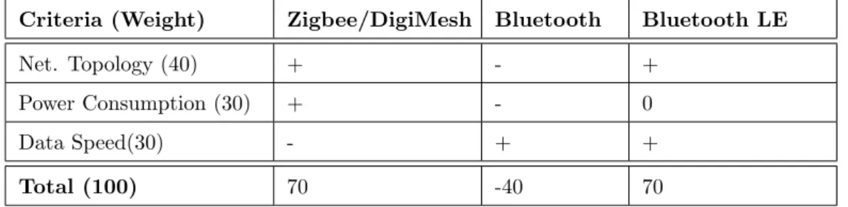
The wireless protocols considered in the trade-off are: Zigbee, Bluetooth and Blue-tooth Low Energy, and the criteria used are: Network topology (40/100), power consumption (40/100) and data speed (20/100).The result is shown in Table3.2. Re-garding the MSP432P401R SimpleLink Microcontroller LaunchPad it needs addi-tional hardware to implement any of the wireless protocols, reason why the hardware limitations are not a decision criterion for the trade-off.
Criteria (Weight) Zigbee/DigiMesh Bluetooth Bluetooth LE
Net. Topology (40) + - +
Power Consumption (30) + - 0
Data Speed(30) - + +
Total (100) 70 -40 70
Table 3.2: Trade-off table wireless communication protocol
The network topology criterion refers to the organization and operation of the different nodes belonging to a same network. This parameter has been given a weight of 40/100 due to the fact that the MAES platform communication may form a multi-master
distributed system. Concerning this criterion Bluetooth scored negatively due to the fact that in a Bluetooth network (piconet) there be can only one master, the rest of the devices are considered slaves, although is possible for a slave to become a master, it can be so in another piconet, resulting in a interconnection of piconets known as a scatternet[35]. Still a scatternet does not provide the adequate topology for MAES inter-platform communication because of the complexity of implementation and scalability of a scatternet where all the platforms must be masters in their own piconet and at the same time be slaves in the other piconets. On the other hand the new version, Bluetooth Low Energy has been developed as an improvement to standard Bluetooth, where now the standard allows the nodes to be arranged in a mesh, which gives it a positive mark on the trade-off. Lastly, just like Bluetooth Low Energy[36], Zigbee can be arranged as a mesh, star or cluster tree topology, in addition in a Zigbee network two types of devices can participate, know as full function device (FFD),who can receive and send messages between any device on the network acting as coordinators [37], and reduce function device (RFD), who can only talk to FFD but not between other RFD.
On power consumption, Zigbee and Bluetooth Low Energy scored positively as in contrast to Bluetooth. The reason they have an advantage is due to the fact that the protocols have a sleep mode for end devices operate on a low power consumption state when no action is required from them while still been ready to wake up and transmit almost instantly when a incoming message arrives[34, 36].
Finally regarding data rate both Bluetooth and Bluetooth Low Energy are able to have a data throughput up to 2Mbps, while Zigbee’s maximum throughput is of 250kbps [35], which shows that is the only one who scored negatively in regards of the data rate criterion.
3.3
Protocol Selection
The last two sections where dedicated to argue which is the best communication protocol that fits the design requirement for the implementation of inter-platform communication using MAES framework. The protocols where divided between Wired and Wireless, it is the design decision to choose the I2C, which is a wired protocol
On the other hand, as previously mentioned, the wireless protocols have been only implemented in satellite communications for the data bus, meaning that they are used for the data retrieval from instrument sensors, therefore this thesis considers Zigbee and Bluetooth Low Energy implementation and testing as possible secondary protocols that could provide redundancy to the inter-platforms communications.
Chapter 4
Protocol Design for an
Embedded Multi-Agent
System Inter-Platform
Communication
This chapter presents the design choices for the communication protocol, following the FIPA guidelines for Multi-Agent Systems, which addresses the first research question of this thesis: What is the most efficient architecture that best manages the resources for communication applications in multi-platform systems running MAES?. The first Section discusses two message routing strategies to then choose the one that best suits the requirements mentioned on Section 1.2. Next Section 4.2 the implementation of the inter-platform communication protocol is described. Section 4.3 presents a visual summary of the inter-platform communication protocol.
4.1
Message Routing Strategy
com-plicitly specify what protocol that must be used when inter-platform communication is intended, the specification mentions how the packet must be composed,as it is mentioned in section 2.4.1.Therefore this thesis describes two design choices called: dynamic approach, static approach, to later choose to implement just one.
Both approaches part from the understanding that the sender agent knows to whom it wants to communicate with, much as in other type of communication system, the destinatary is always known, the only thing that both approaches handle is how they deliver the messages. The message packet is comprised by the header(Sender I2C address, Receiver I2C address, and message type) and the payload (Sender AID, Receiver AID,message type and content).
4.1.1
Dynamic Approach
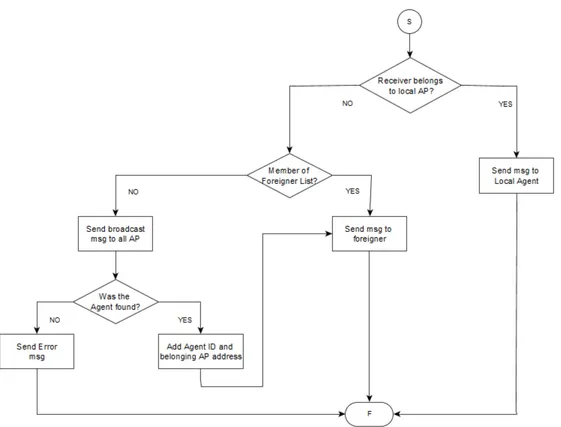
Fig.4.1 shows the flow chart of how the Message transport system (MTS) would resolve the destination of an outgoing message sent by a sender agent to a receiver agent. First the MTS has to discern if the receiver agent is local or foreign, meaning that a local destination is where the receiver agent is registered to the same platform as the sender agent and a foreign destination is where thereceiver agent is registered to a platform different as the sender agent.
If the destination happens to be local, the MTS proceeds as it is already implemented by MAES Framework, on the other hand if the destination happens to be foreign the next action is to determine to which of the other platforms the receiver agent belongs to. The way is done is by inquiring each of the platforms’ AMS (Agent Management System) one by one through the I2C bus to determine which one has the receiver agent
registered. The AMS who has registered the inquired receiver agent will answer and send a message that contains the I2C address of the platform it belongs to, then the
inquirer AMS will add the receiver’s agent ID and the I2C address, thus populating
a foreign agent routing table, so the next time a message is destined to that foreign agent, the local AMS does not have to repeat the inquiring process.
Subsequently after knowing the I2C address, by looking at the foreign routing ta-ble,the MTS composes the data message’s header and payload (Packet) and sends the message directly to the platform where the receiver agent is registered.
Figure 4.1: Dynamic Message Routing design choice
When a request message arrives to a foreign MTS inquiring for the membership of an specific agent, the AMS searches within it’s own list of registered agents and answers to the inquirer Agent platform when the agent is in fact registered to it. At the same time the AMS stores the agent ID and platform address of the sender agent, so in one message two actions take place and in the future the AMS does not have to send a request message for that agent, see Fig. 4.2
It can happen that an agent is de-registered (killed) from it’s AMS,when this happens an update message is sent to the other platforms, so they all remove the agent from their foreign agent routing table, thus liberating memory space from the platform, see Fig. 4.3.
Figure 4.2: Flow Chart of the a message request
Figure 4.3: Flow Chart of the a message update
4.1.2
Static Approach
The static approach is that at start-up each platform shares its own information, meaning the platform’s ID which then correlates to its own I2C address, with the rest of the platforms, so all platforms have the complete information of each other before any message exchange is done. After, when the sender agent sends a message
to a receiver agent the MTS has to first check if the receiver agent is local, if it is it proceeds as it is already implemented by MAES Framework, on the contrary when the receiver agent is not registered to the same platform as the sender agent the next step is to search by the agents AID, the agent AID in it self is a concatenation of the platform’s ID and its own ID, so when the search is done in the table previously shared, the MTS takes from the agent AID the portion of the the platform’s ID and determines what is the platform’s I2C address so the MTS composes the data
message’s header and payload (Packet) and is sent to the platform the receiver agent is registered to.
When the message is received at the destination platform, the MTS looks in the payload for the receiver’s agent AID, and confirms that the agent is registered to the AMS. So if in the case occurs where the agent is de-registered (killed) from it’s AMS the receiver platform will send a NON UNDERSTOOD to the sender agent and the packet will be dropped.
4.1.3
Approach selection
The premise is that MAES Framework is intended to be used for the development of real time applications in the space industry, specifically for them to be used inside on CubeStats, which delineates that the dimensions must be of 10cm x 10cm x 10cm and weight about 1kg. Furthermore they are constraint on volume and power consumption meaning that the number of platforms that are going to be connected between each other is limited to at least two but depends on the final application and the hardware used, where the casing, cabling and sensors must be considered in the final design. The Static Approach fits best into the CubeSat environment because the setting is contained enough to consider it a small network. The advantage of using the static approach is that it demands less CPU/Memory overhead for storing each foreign agent’s AID and corresponding I2C address of the platform it belongs to and does
not add processing time for the inquire of the foreign agent’s location. Furthermore there is no bandwidth overhead because updates are not shared between the platforms, thus providing more control on the traffic that is routed.
4.2
Inter-platform Communication Implementation
For this thesis the hardware used is the MSP432P401R SimpleLink Microcontroller LaunchPad that uses the Texas Instruments proprietary real time operating sys-tem called TI RTOS SYS/BIOS where applications are organized by a collection of threads, meaning that each application’s function is encapsulated in a stream of in-structions, which are executed by the processor. SYS/BIOS supports four different types of threads: Hardware interrupts (Hwi), Software interrupts (Swi), tasks and the idle thread. MAES Framework architecture is based on tasks, as each task have their own stack unlike Hwi and Swi who share the same stack (system stack). This allows the task to takeover a resource and make other tasks wait for the release of the resource (block). Tasks execute based on their priority level, there are 16 priority levels where level 0 is the lowest priority and 15 corresponds to the highest priority, while level -1 means that the tasks is inactive. The definition of each priority must be defined by the developer, this gives the developer flexibility as to decide how the tasks are going to be executed.
As discussed before MAES’ framework architecture is based on tasks, meaning that each agent equals a single task within the framework, therefore whoever has the highest priority is the one who is currently running and the one agent who can request an action to another agent.
Each interaction between agents is done through the exchange of messages, TI-RTOS has a particular set of modules that allow tasks to communicate with each other which are: queues,events, semaphores and mailboxes. MAES Framework Message Transport System (MTS) is mapped to the usage of mailboxes, each agent has it’s own mailbox, so for example a sender agent can signal when a message is posted to the receiver agent (notifies of an incoming message),for which the receiver agent’s mailbox prepares to receive the data from the sender.
4.2.1
Agent Platform and Agent message classes extension
The trade-off analysis conducted on Chapter 3 was based on the available hardware MSP432P401R SimpleLink Microcontroller LaunchPad who features 64KB RAM memory, 256KB Flash memory, four I2C modules and an ARM Cortex-M4 processor[29].
In addition MAES Framework is written in C++, as it is an Object Oriented Pro-gramming Language, who’s theory is suitable for implementing Multi-Agent Systems. The base version of MAES Framework contains four main classes: Agent class,Agent Message class,Agent Platform class, and Behaviour-related classes[4]. This thesis in order to bring out the capabilities of inter-platform agent communication extends the Agent Message, Agent Platform classes and adds the Communication class to the already existing MAES library.
The extension of the Agent Platform class adds the methods needed to add the Agent Communication Channel (ACC), who is the service on MAS that is in charge of determining if the messages are local or need them to be encapsulated into the payload of the ACL message to deliver them to an foreign platform (Fig.4.4). As well the ACC is where the foreign messages arrive to the platform and where they are decapsulated to later be forwarded to the receiver agent.
Figure 4.4: Block description of the communication method used for MAES inter-platform communication.
On MAES the ACC is mapped as the I2C Master, Slave and Postman agents, see Fig.4.5. They are all initialized like a regular agent, when the method is ran it creates their unique task and mailbox with its corresponding Agent AID (task handle) and mailbox handle. In addition when the intend is to use the inter-platform communi-cation, the developer has to know that for this case the agent priority allocation of MAES changes, what this means is that the I2C Slave agent now becomes the agent
with the higher priority, as a result, the incoming messages from other platforms are addressed as soon as possible, because they are considered as an external interruption that must take precedence over local message addressing. Following is the I2C Slave’s
”Postman”, the Postman is an agent that is in charge of the unpacking of the packets received by the I2C Slave, next is the I2C Master agent with the third highest priority as a result of the possible immediate need to send a response of an external message that arrived from a foreign agent. Lastly the AMS agent becomes the agent with the fourth highest priority, the rest of the local agents that are created follow the already established priority description from the base MAES Framework, which is developer defined.
Regarding the Agent Message class, the extension takes advantage of the polymor-phism functions have, which allows for a member function to act differently according to the type of object that invokes it. This property is used for the function send, see 4.6, where depending on the intended recipient, the message is addressed to either the local agent or to a foreign agent, the distinction lies in how the receiver agent’s is called. This is an important distinction because when an agent is registered to a platform and therefore becomes a member of the platform’s AMS, the agent is given a unique name inside the platform it belongs, which is called the Agent ID, this is the name by which the other local agents refer to when they choose to send a message to it. With respect to the inter-platform communication each agent has what can be called an “Alias” by which agents from different platforms can refer to it. The agent’s “Alias” is an unsigned 16 bit integer (uint16 t), who concatenates in the 8 MSB with the number of the Platform’s (uint8 t) identifier and in the LSB 8 bits the agent’s (uint8 t) identifier, the agent identifier is an unique integer from 1 to 62 that the developer defines, this range is a convention because it’s defined in MAES framework that the max agents a platform can host is 62.
Each Agent Alias represents the global name by which the agent is referred to inside the whole MAES Framework, it is the concatenation of the integer ID and the in-teger platform ID, this means that even if the inin-teger ID is the same on more than one platform, there will not be a conflict of Aliases because the identification of the platform ID is the distinction between the Aliases. Also, it is not possible inside a platform that more than one agent has the same Alias, because during compilation an error will be prompted to the user that the definition of an Alias is duplicated.
Figure 4.6: Snippet of class Agent Msg regarding the send function.
Both send functions construct the ACL message with the message parameters:sender , receiver ,performative and content and post the message to the mailbox of the intended recipient. So what happens when the intended recipient belongs to another platform? Which mailbox does the the message is posted? The answer is the ACL message is posted to mailbox of the I2C Master, which is the agent that takes the
recently posted ACL message (which is now considered the payload) and adds the en-velope that contains the parameters: to-from and acl-message, which is described more in detail in the next subsection 4.2.2.
4.2.2
Agent Communication Channel Class
The Communication class encases the usage of the I2C protocol, where each platform
has the ability to act as an I2C Master when a local agent chooses to send a message to
a foreign agent, or act as Slave when an incoming message arrives with the destination of a local agent.The Master and Slave each have their own task (each are an individual agent) and consequently their own stack allowing for incoming and outgoing messages to be allocated in different queues thus not creating conflicts on the utilization of the I2C channel, which means the Master and Slave each use one out of the four MSP432P401R Launchpad modules.
After a message from a local agent intending to communicate with a foreign agent is posted in the I2C Master’s mailbox, the I2C Master agent, receives the message and
proceeds with the encapsulation of the contents into the I2C Packet, the ACL message with the sender Alias , receiver Alias , performative and content are added to the payload structure of the packet. After the Platform receiver address, Platform sender address are placed in the header structure of the packet, see Fig 4.7.
The I2C Master determines the Platform receiver address looking at the receiver Alias field and correlates the MSB 8bits of the agent’s (uint16t) Alias with the table of I2C platform addresses that are already registered at start-up. When the 8bit I2C
address is determined, it is placed in the Platform receiver address field. The Platform sender address parameter is filled by copying the local platform’s I2C address.
Figure 4.7: I2C Packet encapsulation of the inter-platform message exchange.
The I2C packet refers to a uint8 variable that encapsulates the header and the ACL message, that is passed by value to the I2C Master driver API, where a parameter is
the uint8 variable previously mentioned. The other parameters that are filled are the 8bit I2C receiver address, packet size and the intention of writing information to the
I2C Slave of the receiver platform.
At reception the I2C Slave agent receives the I2C packet and after forwards the packet
to the ”Postman”, who first checks the receiver Alias field and compares the MSB 8bits with the platform’s ID, to determine that the message is in fact intended for the said platform. Next the LSB 8bits of the receiver Alias are compared to find the match. The ”Postman” does a inquiry to the platform’s AMS using the receiver Alias and asks for the Agent’s AID. Once the ”Postman” has the Agent’s AID it proceeds to post the ACL message to the new found local agent’s mailbox. After the local agent receives the message and proceeds with the instructions given by the performative and content of the ACL message that were already defined by MAES intra-platform methods. In case the platform address or the agent ”Alias” does not correspond the ”Postman” constructs a I2C packet with a message reply to
4.3
MAES Communication Stack for inter-platform
communication
This chapter can be summarized with a visual representation of the content presented on Fig. 4.8, were it shows how a message from an agent registered on a MAES agent platform goes down through the inter-platform communication protocol layers and then it’s delivered to the other MAES agent platform registered, where the message goes up inter-platform communication protocol layers to reach the intended agent.
Chapter 5
Multi-Agent System
Inter-Platform
Communication
Implementation and Testing
This chapter is dedicated to the verification of operation of the inter-platform commu-nication as to observe the implementation’s operation. For this, three applications are used to show the verification of the inter-platform communication protocol execution, the precision of the message round trip time and the relation between the number of agents accessing simultaneously the I2C bus and the delay.
5.1
Hardware setup
This section describes the hardware setup used to perform all the below described measurements. The launchpad used is the Texas Instruments MSP432P401R Sim-pleLink Microcontroller LaunchPad (Fig. 5.1), who features 64KB RAM memory, 256KB Flash memory, a low power ARM 32 bit Cortex-M4F microcontroller (MCU), up to 48 MHz system clock, additionaly has on-board probe for programming and
de-bugging, two buttons and two LEDs for user interaction,backchannel UART through USB to PC,lastly four I2C modules and up to eight SPI modules. [29].
Figure 5.1: MSP432P401R Launchpad [29]
In order to carry the measurements to verify the behaviour of the implementation, two MSP432P401R Launchpads were used. They were connected between each other using the pinout described on table 5.1 for the I2C Master and Slave connection, this because of the need to use two libraries (I2CMaster.h and I2CSlave.h) from Texas Instruments that run with the Real Time Operating System (RTOS). A complete view of the interconnection can be seen on Fig. 5.2. where the value of the two pullup resistors is of 10 kΩ , and the voltage supplied is of VCC = 3.3V , and the bit
rate used was 100 kHz.
Master pins Pull-up resistor Slave pins UCB1SDA (P6.5) 10 kΩ UCB0SDA (P1.6) UCB1SCL (P6.4) 10 kΩ UCB0SCL (P1.7)
GND NONE GND
Figure 5.2: MSP432P401R Launchpads complete connection
5.2
Inter-platform communication protocol
verification
This experiment is intended to verify the inter-platform communication protocol im-plementation described in Chapter 6.2. The scenario consists in having an agent from one Launchpad send a message to a foreign agent from another Launchpad and expect an answer from the foreign agent. All measurements are performed using the Texas Instruments proprietary Code Composer Studio (CCS) Version 8.2.0.00007 and the RTOS Analyzer’s Execution Analysis tool, to examine how the agents execute and interact within the MAES Framework.
Therefore, as explained in section 5.1 two MSP432P401R Launchpads were connected with one another and each had downloaded MAES Framework updated library. On this scenario the size of the mailboxes for the I2C Master and I2C Slave are of 3
messages each and each Launchpad allocates a total of 5 agents that are listed on table 5.2 for Launchpad 1 & table 5.3 for Launchpad 2. Launchpad 1 allocates agent ”Write” who sends a message with the performative:REQUEST to agent ”Read” from Launchpad 2,which upon receiving the message answers to agent ”Write” with a message stating the performative:CONFIRM , which means that it acknowledges that it received the message from Launchpad 1.
Name Priority I2C Slave Task 15 Postman Task 14 I2C Master Task 13 AMS Task 12 Write Task 1
Table 5.2: Agents on Launchpad 1
Name Priority I2C Slave Task 15 Postman Task 14 I2C Master Task 13 AMS Task 12 Read Task 1
Table 5.3: Agents on Launchpad 2
All measurements were executed using launchpad 1 as reference considering it houses agent ”Write”,therefore the results shown below correspond to launchpad 1’s view-point. First upon start-up all agents initialize before they can perform any of their tasks, the initialization process takes place in accordance with the design of MAES framework, which first sets up the agents from highest priority to lowest priority sequentially,as shown in Fig. 5.3 the I2C Slave, Postman and I2C Master agents
are the ones that initialize first, followed by the AMS agent, who then allows agent ”Write” to initialize and be ready for operation, which sends a message with the performative:REQUEST to agent ”Read”(Launchpad 2).
Figure 5.3: Agent Initialization on launchpad 1
After the initialization of all the agents has been performed, immediately agent ”Write” takes over the execution and composes the ACL message with the performa-tive:REQUEST,sender,receiver and content and posts the message to the I2C Master’s mailbox, as is shown on mark 1 from Fig. 5.4. Mark 2 shows the I2C Master pre-empting agent ”write” to receive the message from its mailbox, compose the packet with the header and payload (ACL message) and initializing the I2C channel, after
sage composition and sending. Marks 4 & 5 show the I2C Master agent sending the message to through the I2C bus to Lauchpad 2.
Figure 5.4: Message trace of a sent message on launchpad 1
Finally the ”idle loop” task, who is part of the TI RTOS, runs when no other task is scheduled to run, in the case shown in Fig. 5.5 it runs because it is waiting for the arrival answer message from Launchpad’s agent ”Read” (mark 1), after mark 2 shows how the I2C Slave executes when it has received the answer message from
Launchpad 2. On mark 3, the Postman takes over execution, where the header of the packet gets read and the Postman determines that the message is intended for agent ”Write” who is registered to the platform’s AMS, so it posts the packet’s payload (ACL message) to agent ”Write’s” mailbox. Mark 4 shows agent ”Write” executing, meaning it receives the confirmation message from agent ”Read” thus marking the end of the send/receive cycle, afterwards the cycle starts again for the next message.
5.3
Precision of the Inter-platform communication
protocol
This experiment is intended to determine the precision of the I2C bus and MAES
Framework while transmitting and receiving inter-platform messages. The scenario is the same as the one exposed on Section 5.2. A sample of 300 messages was collected, where the time that takes agent ”Write” to send the request message and to later receive the answer from agent ”Read” was measured. Fig. 5.6 shows the histogram, where it shows that probability of obtaining a RTT between 5.82 ms and 5.84 ms is of 45%, which can be considered as the minimum time an agent has to wait for a response after sending a message to and foreign agent, when the I2C bus is working
with perfect conditions.
Figure 5.6: Histogram showing the round trip time of 300 samples sent from Launch-pad 1 to LaunchLaunch-pad 2
According to the MSP432P401R SimpleLink Microcontroller LaunchPad’s data sheet[38], the time required for the I2C to send a packet is given by the time values shown in Table 5.4. With the information below the time that the I2C takes to complete one
data transfer can be determined by equation 5.1
Parameter Time
tSU,ST A: Set time for START 5.5µs
tSU,DAT: Set time for STOP 5.5µs
tHD,DAT: Hold time for data 80 ns
tSU,ST O: Set time for data 5.5µs
Table 5.4: I2C Timing for 100 kHz
TI2C= tSU,ST A+ 9(databytes+ addressbyte)(tSU,DAT+ tHD,DAT) + tSU,SDL (5.1)
Where:
databytes: is the number of bytes of the data to transfer
addressbyte: is the byte of I2C Slave address
On this regard, if we consider the mean time obtained from Fig. 5.6, which is 5.84 ms, the time it takes the I2C (equation 5.2) to send a packet can be determined by
substituting the constants from equation 5.1 with the values from Table 5.4, knowing that the size of the packet is of 10 bytes. This means that from the round trip time around 1 m sec corresponds to the time that takes the I2C bus to send and receive a packet. The 4.84 ms left are attributed to the processing time of Launchpad 1 to compose the message and the time Launchpad 2 takes to interpret the received message.
5.4
Relationship between number of agents and the
delay
The purpose of this experiment is to determine the effect on the round trip time on an agent when the number of agents transmitting at the same time on the I2C bus
increases. To obtain the results the same setup as described in section 5.1 was used, this time the number of agents on each Launchpad was increased simultaneously, first starting with one agent (agent ”Write” on Launchpad 1 and agent ”Read” on Launchpad 2) until reaching 14 agents operating on each Launchpad, counting for a total of 14 trails. On each trail all agents where triggered to start sending a message with the performative:REQUEST at the same time thus measuring the round trip time for agent ”Write”. The number of samples for each trail was of 300 samples. The measurements are taken from launchpad 1’s viewpoint. Fig. 5.7 shows a Box Plot, where it shows the precision of the samples holds as seen on Section 5.2. Addi-tionally the Box Plot shows that when the number of agents , accessing the I2C bus
simultaneously, increases the round trip time for agent ”Write” increases as well. This result indicates that the relationship between the number of agents on a Launchpad and the delay increases linearly. Table 5.5 shows how the delay [ms] of agent ”Write” increases when the number of agents on each Launchpad increases.
This linear relationship resembles the results obtained for an analysis conducted to characterize the bus performance of satellite missions, in this case CAN bus was used as the communication channel between the attitude and orbit control subsystem (AOCS) that is based on a multi-agent system application that controls a distributed architecture of sensors. According to Carvajal-Godinez [39] the results show that the bus utilization increases linearly,as well, in function of the number of nodes in the network as long as the bus saturation is not reached. For MAES Framework maximum capacity of the I2C was not reached because the Launchpad ran out of RAM memory, forcing the experiment to be stopped at 14 agents, however both results coincide on the fact that for Multi-Agent based systems, the delay of the messages hold a linear relationship with the number of agents/nodes for I2C and CAN buses,as long as the
Figure 5.7: Blox Plot of the round trip time of agent ”Write” vs the number of agents running
Num Agents Round trip time [ms] Delay [ms] 1 5.861036 —– 2 6.016338 0.155302 3 9.138593 3.277557 4 12.18487 6.323843 5 15.40223 9.541193 6 18.51174 12.65070 7 21.55260 15.69157 8 24.64142 18.78039 9 27.97065 22.10962 10 31.05134 25.19030 11 34.01641 28.15538 12 37.10220 31.24117 13 40.34537 34.48433 14 43.24178 37.38075
Table 5.5: Mean round trip time of agent ”Write” and the delay as the number of agents increases
![Figure 1.1: First centroamerican CubeSat launched as part of the Irazu Proyect for monitoring climate change in the tropical forests of Costa Rica [2] [3].](https://thumb-eu.123doks.com/thumbv2/123dokorg/7496983.104233/11.892.204.692.167.495/figure-centroamerican-cubesat-launched-proyect-monitoring-climate-tropical.webp)

![Figure 2.2: FIPA reference model showing the relationship between components of the system [18]](https://thumb-eu.123doks.com/thumbv2/123dokorg/7496983.104233/22.892.289.618.164.546/figure-fipa-reference-model-showing-relationship-components.webp)
![Table 2.2: OSI Application’s sub-layers[6]](https://thumb-eu.123doks.com/thumbv2/123dokorg/7496983.104233/23.892.174.726.168.585/table-osi-application-s-sub-layers.webp)
![Table 2.3: FIPA Envelope Parameters[19]](https://thumb-eu.123doks.com/thumbv2/123dokorg/7496983.104233/24.892.165.794.517.854/table-fipa-envelope-parameters.webp)
![Figure 2.4: Communication Methods between different APs [19]](https://thumb-eu.123doks.com/thumbv2/123dokorg/7496983.104233/25.892.211.684.552.737/figure-communication-methods-between-different-aps.webp)
![Table 2.4: FIPA ACL Message Parameters[20]](https://thumb-eu.123doks.com/thumbv2/123dokorg/7496983.104233/26.892.168.762.341.731/table-fipa-acl-message-parameters.webp)