Autore:
Michele Carta _______________
Relatori:
Prof. Umberto Mengali _____________________ Prof. Ruggero Reggiannini _____________________ Ing. Vincenzo Lottici _____________________
FREQUENCY RECOVERY
AND RECEIVER DESIGN ISSUES
IN FBMC WIRELESS SYSTEMS
Corso di Dottorato di Ricerca in INGEGNERIA DELL’INFORMAZIONE
Acronyms iii
List of Figures viii
1 Introduction 1
2 FBMC Systems 7
2.1 Introduction . . . 7
2.2 FBMC Signal Model . . . 9
2.3 TETRA Enhanced Data Service . . . 13
2.3.1 System Overview . . . 14
2.3.2 Physical and Logical Channels . . . 15
2.3.3 Payload Coding and Interleaving . . . 17
2.3.4 Header Coding and Interleaving . . . 19
2.3.5 Burst Structure . . . 20
3 Carrier Frequency Offset Recovery 25 3.1 Introduction . . . 25
3.2 Signal Model . . . 28
3.3 ML Pilot-Aided Carrier Frequency Offset Estimation . . . 30
3.3.2 ML Estimator and Approximate Schemes . . . 33
3.4 Performance Results . . . 37
3.4.1 Simulation Setup . . . 37
3.4.2 Definition of the Pilot Pattern . . . 38
3.4.3 MEV Performance . . . 42
3.4.4 MSEE Sensitivity to SNR . . . 44
3.4.5 MSEE Sensitivity to the Doppler Bandwidth . . . 46
3.4.6 MSEE Sensitivity to the Frequency Offset . . . 47
3.4.7 MSEE Sensitivity to Doppler Bandwidth Mismatch Errors 48 3.4.8 FER Performance . . . 49 3.4.9 Implementation Issues . . . 51 3.5 Concluding Remarks . . . 53 4 FBMC Receiver Design 59 4.1 Introduction . . . 59 4.2 Signal Model . . . 61 4.3 Receiver Design . . . 62 4.3.1 Timing Synchronization . . . 63
4.3.1.1 Timing Synchronization Complexity . . . 65
4.3.2 Demodulation and Matched Filtering . . . 68
4.3.3 Channel Estimation . . . 69 4.4 Simulation Results . . . 70 4.4.1 Performance of Estimators . . . 72 4.4.2 System Performance . . . 74 4.5 Concluding Remarks . . . 75 5 Conclusions 79
AACH Access Assignement CHannel
AWGN Additive White Gaussian Noise
BER Bit Error Rate
BNCH Broadcast Network CHannel
BS Base Station
CB Control Burst
CFO Carrier Frequency Offset
DAB Digital Audio Broadcasting
DFT Discrete Fourier Transform
DPSK Differential PSK
DQPSK Differential Quadrature PSK
DS Doubly Selective
DSL Digital Subscriber Line
DVB-RCT DVB-Return Channel Terrestrial
ETC-TETRA ETSI Technical Committee-TETRA
ETSI European Telecommunicaton Standard Institute
FBMC Filter Bank MultiCarrier
FDD Frequency Division Duplexing
FER Frame Error Rate
HSD High Speed Data
ICI Inter-Carrier Interference
IDFT Inverse Discrete Fourier Transform
IEEE Institute of Electrical and Electronic Engineers
ISI Inter-Symbol Interference
ITCE Ideal TCE
LAN Local Area Network
LB Linearization Burst
LCH Linearization CHannel
MAC Media Access Control
MC MultiCarrier
MEV Mean Estimated Value
MS Mobile Station
MMSEE Minimum Mean Square Estimation Error
MSEE Mean Square Estimation Error
NDB Normal Downlink Burst
NUB Normal Uplink Burst
OFDM Orthogonal Frequency Division Multiplexing
PAMR Public Access Mobile Radio
PCCC Parallel Concatenated Convolutional Code
PE Propagation Environment
PMR Professional Mobile Radio
PP Pilot Pattern
PR Pseudo-Random
PSAM Pilot Symbol Assisted Modulation
PSK Phase Shift Keying
QAM Quadrature Amplitude Modulation
RAB Random Access Burst
RF Radio Frequency
RM Reed Muller
SC Single Carrier
SCH Signaling CHannel
SICH Slot Information CHannel
SNR Signal to Noise Ratio
SRRC Square Root Raised Cosine
TCE Timing and Channel Estimation
TCE-M TCE-Mismatched
TDMA Time Division Multiple Access
TEDS Tetra Enhanced Data Service
TETRA TErrestrial Trunked RAdio
TU Typical Urban
VDSL Very high speed DSL
Wi-Fi Wireless Fidelity
WLAN Wireless LAN
2.1 FBMC spectral components. . . 10
2.2 Block diagram of FBMC transmitter. . . 11
2.3 Block diagram of FBMC receiver. . . 12
2.4 TEDS transmitter structure. . . 20
2.5 Structure of NDB. . . 22
2.6 Structure of NUB. . . 22
2.7 Structure of CB. . . 22
2.8 Structure of RAB. . . 22
3.1 Pilot pattern schemes. . . 40
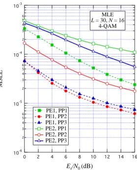
3.2 MMSE of MLE versus Es/N0 for PE1 and PE2 with pilot patterns PP1, PP2 and PP3. . . 41
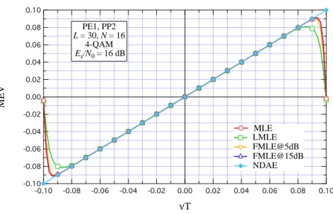
3.3 MEV of MLE, LMLE, FMLE@5dB, FMLE@15dB and NDAE ver-sus νT for PE1 and PP2. . . . 43
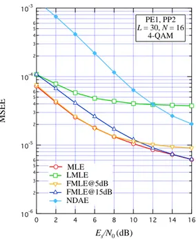
3.4 MSEE of MLE, LMLE, FMLE@5dB, FMLE@15dB and NDAE versus Es/N0 for PE1 and PP2. . . 44
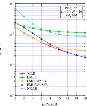
3.5 MSEE of MLE, LMLE, FMLE@5dB, FMLE@15dB and NDAE versus Es/N0 for PE2 and PP2. . . 45
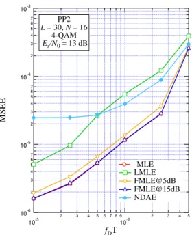
3.6 MSEE of MLE, LMLE, FMLE@5dB, FMLE@15dB and NDAE versus fDT for PP2. . . . 46
3.7 MSEE of MLE, LMLE, FMLE@5dB, FMLE@15dB and NDAE
versus νT for PE1 and PP2. . . . 47
3.8 MSEE of MLE, LMLE, FMLE@5dB, FMLE@15dB and NDAE versus Es/N0 for PE1 and PP2 with ² = 0 and ² = 40%. . . . 48
3.9 FER of MLE, LMLE, FMLE@5dB, FMLE@15dB and NDAE ver-sus Es/N0 for PE1 and PP2. . . 49
3.10 FER of MLE, LMLE, FMLE@5dB, FMLE@15dB and NDAE ver-sus Es/N0 for PE2 and PP2. . . 50
4.1 Block diagram of the proposed FBMC receiver. . . 62
4.2 Generic symbol pattern. . . 63
4.3 Magnitude of the autocorrelation function of z(t). . . . 64
4.4 MSEE of Timing Estimator versus Eb/N0. . . 73
4.5 MSEE of Channel Estimator versus Eb/N0. . . 73
4.6 Curves of FER versus Eb/N0, 4-QAM. . . 74
Introduction
Multicarrier (MC) modulation techniques are the key factor in the field of high data rate transmission over wireless fading channels. It is well known how signal propagation through multiple paths with different delays results in waveform distortion and wide variations in the received signal strength. Specifically, severe inter-symbol interference (ISI) is encountered whenever the delay spread of the channel is comparable to the symbol duration. The countermeasure represented by MC modulations consists of transmitting the information symbols in parallel low-rate subchannels, allowing high data rates to be supported without incurring the detrimental effects of frequency selectivity of the propagation channel.
This Ph.D. dissertation deals with one of the most prominent example of MC modulation, Filter Bank MultiCarrier (FBMC) modulation, and aims at reporting the main results of our research activity carried out over the last three years in the field of FBMC wireless systems.
Initially the focus of our attention concerns the FBMC signal format and MODEM architecture. The most appealing feature of FBMC modulation is the adoption of bandlimited pulse shaping for data symbols transmission on each subchannel. Such a spectral partitioning criterion, besides being the
distinc-tive aspect compared to other MC techniques, OFDM above all, results in a number of advantages: i) reduced sensitivity to narrowband interferers and to frequency misalignment; ii) higher flexibility to allocate groups of subchannels to different users; iii) mitigation of inter-carrier interference (ICI); iv ) possibility of frequency-domain equalization without requiring any cyclic extension. Looking at implementation issues, efficient modulation and demodulation of the signal relies on FFT techniques, as for conventional OFDM, but a polyphase filter bank structure is additionally required both at the transmitter and at the receiver ends, determining a somewhat higher complexity of the overall MODEM architecture. Nevertheless, as a confirmation of the ever increasing interest on FBMC, such a MC modulation has been embedded in several standards, such as very-high-speed digital subscriber line (VDSL) wired services, wireless terrestrial return channel of digital video broadcasting (DVB-RCT) and recently has become part of the release 2 of the terrestrial trunked radio (TETRA) air interface, TETRA Enhanced Data Service (TEDS). In view of the high novelty of the latter standard, which represents a state-of-the-art digital mobile radio system for professional users in both the Professional Mobile Radio (PMR) and Public Access Mobile Radio (PAMR) sectors, we analyze carefully the major PHY aspects of TEDS, i.e, physical and logical channels, payload and header coding, interleaving and burst structure.
Since our interest is in the field of wireless communications, the sequel of our investigations moves towards one of the most challenging and ineludible task con-cerning FBMC transmissions in doubly-selective wireless environments: carrier frequency offset (CFO) recovery. In fact, besides the hurdles due to the multi-path propagation, wireless transmissions are hindered by another negative effect related to terminals mobility. The relative motion of the different objects in the propagation scenario, including the transmitter and the receiver, results in a
pro-shifts and ICI, bringing to light the Achille’s heel of MC systems in this respect. Adding to the mentioned unfavorable effects the inevitable instability of the lo-cal oscillators, robust signal processing algorithms for frequency offset estimation need to be devised.
With this in mind, our main contribution consists on devising an approach for frequency offset estimation that arises from the maximum likelihood (ML) principle. Specifically the optimal ML scheme along with two suboptimal simpli-fied variants are proposed. All of them exhibit an open-loop structure, intended for burst transmissions, and rely on known pilot symbols scattered across the transmitted FBMC burst. Pilot symbols allocation has been designed so as to obtain the best trade-off, for a given overhead, between mean square error (MSE) performance and computational load of the estimation task. The derived optimal pilots placement, evenly arranged in the time and the frequency domains, also contributes to aid channel tracking in time-variant fading environments.
Our proposed algorithms achieve a remarkable estimation accuracy even in adverse channel conditions, and show better performance even at lower compu-tational complexity with respect to non data aided schemes devised for FBMC transmission. Even more, it is worth noting that in the recent literature the vast body of CFO algorithms has been developed for OFDM-based and single carrier systems neglecting the particular FBMC signal format, thus strengthening the novelty of our work.
In the last part of our activity, we broaden our research focus to include tim-ing synchronization and channel estimation issues, in addition to CFO recovery, as essential tasks to be accounted for in the context of wireless transmissions. Specifically, starting from considerations about implementation of efficient
re-ceiver architectures, even in terms of portability and low-power consumption, we look for effective timing-frequency offset and channel estimators suitable for a wireless system such as TEDS.
As a first step of our FBMC receiver design, we consider a simple ML-correlation-based symbol timing recovery algorithm that relies on the transmis-sion of a short known preamble. Then, we aim at carrying out the frequency misalignment compensation through a proper design of the channel estimation scheme, with the intention of removing the explicit frequency estimator block from the receiver. To this end, a modified minimum mean square estimation error (MMSEE) Bayes channel estimator is proposed where the frequency off-set is considered as a random variable incorporated in the time-frequency fading process to be estimated.
A remarkable reduction of the receiver complexity is gained together with a good efficacy of the proposed estimators in typical mobile wireless channel condi-tions, as confirmed by computer simulations. The effectiveness of the architecture is assessed even in presence of frequency and timing offset compatible with spec-ifications of the mentioned TEDS standard, corroborating the validity of our solution.
The thesis is organized as follows:
• Chapter 2 discusses some of the most important features of FBMC sys-tems: signal format, MODEM structure and implementation issues. In ad-dition, a general overview concerning the physical layer of TEDS standard is provided;
• Chapter 3 presents our complete framework concerning the frequency off-set recovery, with particular focus on pilot arrangement design, performance assessment of the proposed algorithms and computational load analysis;
estimation issues;
• Chapter 5 presents the conclusions of our work and provides some consid-erations concerning future developments of our research.
FBMC Systems
The first part of the chapter introduces the basic concepts of wireless communi-cation channels and multicarrier modulation. Then, FBMC modulation, one of the most prominent examples of multicarrier modulation, is presented. We pro-vide a detailed description of the modulator and demodulator architecture which are based on digital signal processing techniques. The last section is devoted to an overview of the main physical aspects of the recent TEDS ETSI standard for PMR/PAMR communications, which relies on the FBMC technique.
2.1
Introduction
Wireless links are a crucial component of existing and future communication systems. Communicating over wireless links poses two main challenges.
On the one hand, reflections of physical objects create multiple paths between transmitter and receiver. Consequently, the receiver observes the sum of several delayed and phase shifted echoes of the transmitted signal giving rise to possi-ble signal distortion and attenuation, commonly referred to as multipath fading. When the delay spread of the paths is comparable to the transmitted symbol duration, energy from one symbol spills over into observations for neighboring symbols, resulting in the so-called inter-symbol interference. Besides causing ISI,
large delay spreads imply that the channel’s frequency response may vary over the bandwidth of the transmitted signal. Thus, such channels are often called
frequency selective channels.
On the other hand, the transmitter, the receiver and the reflectors may in-dividually be in motion in a wireless environment, therefore characteristics (i.e., delays and phase shifts) of each echo observed at the receiver may change appre-ciably over a few symbol durations. A measure of the rate of time variations of the channel is represented by the maximum Doppler frequency which depends on the velocities of the communicating devices and reflectors and on the transmis-sion carrier frequency. In this scenario, the channel has a time selective nature and may cause the so-called effect of inter-carrier interference.
Obviously, given a wireless propagation scenario which is both time- and fre-quency selective, i.e. doubly selective, efficient high data-rate transmissions repre-sents a great challenge. Fortunately, in the last decade, an essential step towards transmission systems highly robust even in adverse channel conditions has been represented by the adoption of multicarrier modulation techniques [1], [2]. In MC modulation, the data stream is split into several substreams and modulated on a set of subcarriers in parallel to face the frequency selectivity of the channel. These data-bearing subcarriers are superimposed, shaped by a modulation pulse, and transmitted. At the receiver, demodulation to retrieve information uses another demodulation pulse. In the form of orthogonal frequency division multiplexing, MC schemes have been embedded in several standards, such as digital audio broadcasting (DAB) [3] and digital video broadcasting (DVB) [4], Wi-Fi wire-less LANs IEEE 802.11a/g [5], Wi-Max broadband wireless access IEEE 802.16 [6], and digital subscriber lines (DSL) services [7]. More recently, the class of orthogonal MC systems has been generalized with the introduction of filter bank multicarrier (FBMC) modulation for high-speed wired access networks [8].
In FBMC systems the data symbols are transmitted over the available sub-channels after suitable bandlimiting pulse shaping. Hence, compared to conven-tional OFDM, FBMC exhibits duality properties as in FBMC the pulse waveforms overlap in time while subcarriers do not overlap in frequency. This entails a num-ber of advantages such as reduced sensitivity to narrowband interferers and to frequency errors, higher flexibility to allocate groups of subchannels to different users, mitigation of ICI, possibility of frequency-domain equalization without re-quiring any cyclic extension [8]. Besides being adopted for very-high-speed DSL services, FBMC is being considered for wireless standards as well, such as those pertaining to the terrestrial return channel of DVB (DVB-RCT) [9] and the new release of TErrestrial Trunked RAdio (TETRA) [10], [11].
2.2
FBMC Signal Model
The basedand representation of a generic FBMC transmitted waveform can be expressed as s(t) =X n N −1X k=0 a(k) n g(t − nT )ej2πk(1+α)t/T, (2.1)
where N is the number of subcarriers, T is the signaling interval and a(k)n is
the n-th data symbol transmitted over the k-th subcarrier. FBMC modulation commonly adopts a shaping filter g(t) which is a unit-energy square-root raised cosine (SRRC) pulse of roll-off factor α.
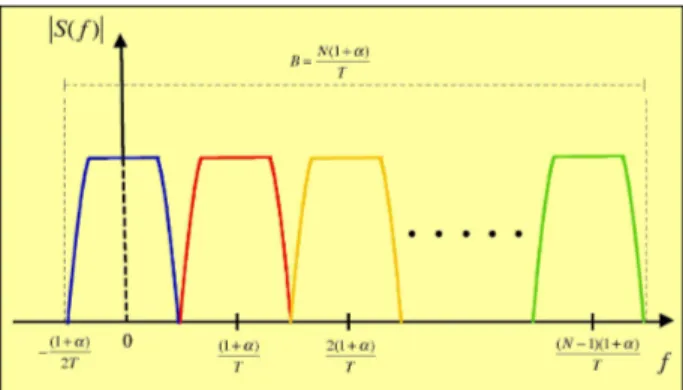
It can be observed that the spectral components of the complex-valued wave-form in (2.1) go from
− (1 + α)
2T ≤ f ≤
(N − 1/2)(1 + α)
T , (2.2)
i.e., its overall bandwidth occupancy is B = N (1+α)T , as shown in Fig. 2.1. Therefore, according to the sampling theorem and constraining M = (1+α)N∆ to be an integer, the signal can be sampled with frequency fs = 1/Ts = M/T
Figure 2.1: FBMC spectral components.
with no aliasing effect and thus the samples of the FBMC signal can be efficiently obtained resorting to digital signal processing techniques [8], as shown below.
First, considering a polyphase decomposition for the time index of the l-th sampling instant as
tl = (Mh + m)Ts, 0 ≤ m ≤ M − 1, (2.3)
the digitized FBMC signal reads
s(m)h ∆ = s[(Mh + m)Ts] = X n N −1X k=0 a(k) n g[M(h − n) + m]ej2πk(M h+m)/N, (2.4)
where we used the standard notation g[n]= g(nT∆ s). It is straightforward that the
waveform in (2.4) can be generated via a conventional OFDM modulator followed by a polyphase filter bank. Specifically, the n-th N-symbol block undergoes inverse discrete Fourier transform (IDFT) and then each element of the parallel IDFT output is processed at the rate 1/T by a different filter. Each impulse response g(m)T [n] of such filters is obtained by the polyphase decomposition of the prototype SRRC filter
g(m)T [n] ∆
= g(nT + mTs) = g(nMTs+ mTs), 0 ≤ m ≤ M − 1. (2.5)
It is worth noting that the number of filters is M (as is M the number of signal samples to be computed in every block of N source symbols), whilst the
number of the IDFT outputs is obviously N (the number of subcarriers). As a consequence, the filter bank also contains a suitable signal memory that feeds the diverse filters of the bank with the appropriate permuted version of the IDFT output. It easy to note that if g(t) is a rectangular function of duration T , the signal in (2.4) becomes an OFDM signal. Moreover, when m ∈ {0, . . . , N − 1},
s(m)h is the IDFT output whereas if m ∈ {N, . . . , M − 1}, s(m)h = s(m−N )h , then the parameter M depends on the size of the cyclic prefix, which is made up of M − N symbols. The samples at the output of the IDFT block are then digital-to-analog converted to produce the time-continuous signal in (2.1), as shown in Fig. 2.2.
Figure 2.2: Block diagram of FBMC transmitter.
The FBMC demodulator can be derived easily following a similar route. Specifically, M received signal samples within a data block are serial-to-parallel converted and then processed by the receiver polyphase filter bank (similar to that used in the transmitter) that performs matched filtering on each subcar-rier. Denoting with x(t) the received signal, the n-th data symbol over the k-th subcarrier after demodulation and matched filtering can be expressed as
z(k)n =∆ N −1 X m=0 X h x(m)h g∗[M(h − n) + m]e−j2πkq/Ne−j2πknM/N (2.6)
where x(m)h = x[(Mh + m)T∆ s] and, decomposing the time index in the following
way
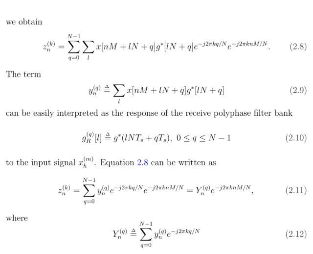
we obtain zn(k)= N −1X q=0 X l x[nM + lN + q]g∗[lN + q]e−j2πkq/Ne−j2πknM/N. (2.8) The term yn(q) =∆ X l x[nM + lN + q]g∗[lN + q] (2.9)
can be easily interpreted as the response of the receive polyphase filter bank
g(q)R [l]= g∆ ∗(lNTs+ qTs), 0 ≤ q ≤ N − 1 (2.10)
to the input signal x(m)h . Equation2.8 can be written as
z(k) n = N −1X q=0 y(q) n e−j2πkq/Ne−j2πknM/N = Yn(q)e−j2πknM/N, (2.11) where Y(q) n ∆ = N −1 X q=0 y(q) n e−j2πkq/N (2.12)
is the discrete Fourier transform (DFT) of yn(q). It is worth noting that each DFT
output is phase shifted by the factor e−j2πknM/N to yield the sufficient statistics zn(k) to the data detection block. FMT demodulator is sketched in Fig. 2.3.
2.3
TETRA Enhanced Data Service
As an example of a real FBMC system, we now provide a brief overview of the main features of the TETRA Enhanced Data Service. TETRA standard, developed by the ETSI, represents a state-of-the-art digital mobile radio system for professional users in both the Professional Mobile Radio (PMR) and Public Access Mobile Radio (PAMR) sectors. The core of the standard has been available since 1994 and ever since the ETSI Technical Committee TETRA (ETC-TETRA) has been continuously enhancing it with the aim of providing the most up-to-date system to TETRA community.
TETRA’s main distinctive features from public commercial 2G and 3G mobile radio systems consist on extensive group call (including dynamic group assign-ment), closed user group and dispatcher operation and control, fast call set-up (300 ms), highly reliable network, direct mode operation often supported with gateway/repeater devices, end-to-end encryption, and many others.
However, the recent and rapid upwards trend in the data speed of mobile radio networks and the increasing popularity of Internet ”contents” and multimedia services prompted ETC-TETRA to develop a Release 2 of the TETRA standard, with the aim of reaching at least a ten-fold increase in the actual data speed limit of 28.8 kbit/s. The task of developing the High Speed Data (HSD) part of TETRA Release 2, suitable for IP-based high-speed multimedia applications was completed at the end of 2005. The major outcome of this standardization process is TEDS which is available since 2006 as the ETSI Technical Standard TS 100 392-2 V 3.1.1 [10].
A prove of TETRA appealing features and of its great worldwide success in the professional community is confirmed by 2006 figures: some 40% of countries around the world have adopted this standard. Almost half of the usage in the PMR sector is attributed to Public Safety organizations (police, fire and
ambu-lance services) whilst a quarter has been taken up by transportation industry. Utilities and military applications amount to 6% each. In addition, the PAMR sector’s usage of TETRA, currently at 3%, is expected to rise as a result of the last enhancement of the standard.
2.3.1
System Overview
In designing the physical layer for TEDS, maximum backward-compatibility has been warranted with the existing narrow-band TETRA 1 standard. To this aim, access to the TEDS channels is only allowed via the TETRA 1 control channel using a 4 timeslot TDMA-based access technique.
However, to support wideband multimedia services whilst ensuring reliable link performance over heavily doubly selective fading mobile channels, several up-to-date technological choices have been made for TEDS, mainly in the PHY layer, ranging from:
• adoption of MC filter bank-based modulation to achieve a robust perfor-mance even on frequency-selective fading channels, for a total number of (2.7 kHz spaced) subcarriers ranging from 8 for the 25 kHz channel to 48 for the 150 kHz channel;
• spectral-efficient multilevel modulation schemes, 4-QAM, 16-QAM and 64-QAM, to boost the system data throughput and achieve a real HSD capa-bility. These QAM schemes plus the π/8-D8PSK scheme are additional to the π/4-DQPSK modulation scheme used in TETRA 1;
• use of a powerful turbo-code for payload channel encoding with 3 available channel coding rates, namely 1/2, 2/3 and 1;
• separate channel encoding for short ”header” blocks capable to outperform the payload performance and enable reliable slot decoding and network
operations;
• flexibility of selecting the required data throughput from a wide range ex-tending to beyond 500 kbit/s;
• use of a link adaptation technique to improve the system performance (e.g., overall message throughput), based on choosing adaptively the modulation level, the coding rate and possibly the channel bandwidth according to the varying channel propagation conditions;
• use of ”sectored antennas” as a means of extending the TEDS high speed channel coverage to that of the TETRA 1 control channel without a need for additional base station sites.
In addition to the above PHY layer enhancements, a number of innovative features have been added to the TEDS higher layer protocols to support efficient IP packet data service over the air interface (with point and point-to-multipoint capabilities).
2.3.2
Physical and Logical Channels
The TEDS air interface is based on TDMA, which ensures compatibility with the previous TETRA 1 standard [10]. The basic TDMA frame consists of 4 timeslots, each of which has duration of 14.167 ms, and can be optionally divided (to increase efficiency for, e.g., random access by MSs) into two equal subslots. In addition, the TDMA structure includes multiframes (18 frames each) and hyperframes (60 multiframes each). Each timeslot, associated to a pair of RF frequencies for frequency-division duplexing (FDD), forms a physical channel. The latter conveys the traffic and signalling messages in the form of logical channels that are packed by the MAC layer, the interface between the higher protocols and the TEDS radio subsystem.
The physical content of a timeslot (or subslot), referred to as a TEDS burst, is arranged in the frequency and time domains according to 5 types of symbol patterns:
1. Control Burst (CB), used by the MS to transmit control messages to the
BS;
2. Normal Uplink Burst (NUB), used by MSs to transmit control or traffic
messages to the BS;
3. Normal Downlink Burst (NDB), used by the BS to transmit control or
traffic messages to the MS;
4. Random Access Uplink Burst (RAB), used by MS to transmit random access
control messages to the BS;
5. Linearization Uplink Burst (LB) and Linearization Downlink Burst (LDB),
used by the MSs and the BS, respectively, to linearize their transmitters. The TEDS MAC layer supports 5 types of Control CHannel (CCH) for sig-naling and packet data messages, namely:
1. the Broadcast Network CHannel (BNCH-Q) contains control network infor-mation that is sent to all MSs;
2. the Signalling CHannels SCH-Q/D, SCH-Q/U, SCH-Q/HU which indi-cate (according to different combinations of modulation/coding and channel bandwidth) full size message downlink, full size message uplink, half size message uplink, respectively, and SCH-Q/RA. The SCH-Q/D is used by the BS to send messages to MSs whereas SCH-Q/RA contains a random access uplink message, and is associated with only 25 kHz bandwidth, 4-QAM and coding rate r = 1/2;
3. the Access Assignment CHannel (AACH-Q) is present on the transmitted downlink slots and contains the assignment of the uplink and downlink slots on each physical channel;
4. the Slot Information Channel (SICH-Q) is used in both uplink (SICH-Q/U) and downlink (SICH-Q/D) to indicate the modulation and coding used in the remainder of the slot or subslot (uplink only);
5. the Linearization CHannel (LCH-Q) is used locally by the BS and MSs to linearize their transmitters.
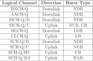
The mapping of the above TEDS logical channels into physical channels is sum-marized in Tab. 2.1
Logical Channel Direction Burst Type BNCH-Q Downlink NDB AACH-Q Downlink NDB SICH-Q/D Downlink NDB SICH-Q/U Uplink NUB, CB
BLCH-Q Downlink LDB CLCH-Q Uplink LB SCH-Q/D Downlink NDB SCH-Q/U Uplink NUB SCH-Q/HU Uplink CB SCH-Q/RA Uplink RAB
Table 2.1: Mapping of TEDS logical channels into physical channels.
2.3.3
Payload Coding and Interleaving
The TEDS PHY adopts two powerful channel encoding techniques, one based on the parallel concatenated convolutional (PCCC) turbo code [12], [13] for the payload field, and the other based on a Reed-Muller (RM) block code [14] for the header section.
As far as payload encoding is concerned, let us consider the binary information bits in the form of MAC blocks, belonging to one of the following logical channels SCH-Q/HU, SCH-Q/U, SCH-Q/D, SCH-Q/RA and BNCH-Q. Before mapping to the burst payload field, the information stream is fed into a rate-r PCCC turbo encoder. The latter is composed of two identical recursive systematic convolu-tional (RSC) encoders concatenated via an inner interleaver of length depending on the burst format, modulation and coding rate. Each RSC is an 8-state encoder having the same structure as that standardized by the Third-Generation Part-nership Project (3GPP) [15], with feedforward and feedback generators given by respectively 15 and 13 (both in octal). Further, the information block is properly terminated, i.e., the last 3 bits at the input of both the upper and lower RSC are chosen so as to force the encoder to the final zero state. The two RSC schemes share the same information bit stream, in the sense that the lower one receives the same information bits as the upper one, but in random-like permuted order.
The near-to-optimal pseudo-random (PR) interleaver originally proposed in [12], has been replaced in the TEDS project by a quadratic-congruence inter-leaver [16], whose mapping rule between the input and output indices (depending on the burst format) can be computed ”on the fly” by means of a deterministic mapping formula. This avoids the use of large memory-consuming lookup tables, but still ensures performance similar to the PR scheme. The parity (redundant) bits out of the two RSC encoders are properly punctured to achieve the desired overall rate r, namely r = 1/2 or r = 2/3, depending on the required level of link performance.
The payload coded sequence, i.e., the systematic (information) and parity (re-dundant) data bits, are then mixed again using a channel interleaver based on a linear-congruence mapping law to exploit the inherent time-frequency diversity of the channel.
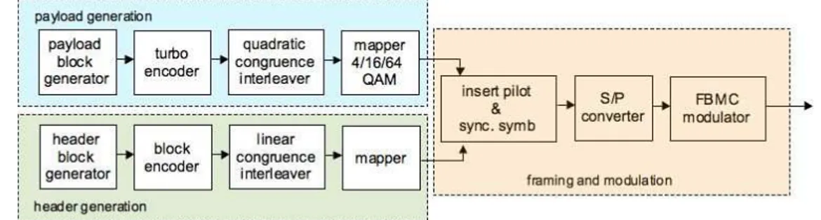
The turbo coded bits are then mapped onto the multilevel QAM constellation through a Gray-like coding scheme, thus following the (suboptimum) pragmatic approach [13], wherein binary turbo coding and multilevel modulation (and thus, the corresponding demodulation and decoding functions at the receiver) are per-formed independently. Three modulation formats are available, namely 4-QAM, 16-QAM and 64-QAM, that combined with the above coding rates correspond to different burst profiles of varying robustness and data throughput. The payload generation chain is depicted in the blue box in Fig. 2.4.
2.3.4
Header Coding and Interleaving
Unlike payload field coding, the binary information bits conveyed by the logical channels SICH-Q/U, SICH-Q/D, and AACH-Q are mapped to the header field of the CB, NUB and NDB bursts after undergoing proper channel encoding based on the Reed-Muller block code [14].
Such a choice can be motivated as follows: i) the limited number of header information bits, namely 5 for CB and NUB, and 20 for NDB, prevents the use of turbo-like codes and leads naturally towards the selection of block codes; ii) header decoding performance must be better than that of the payload decoder for all burst formats because the former is crucial for reliable slot decoding and related network operations. Hence, the 5 CB and NUB header bits are encoded using the Reed-Muller (16,5), or RM(16,5) for short, yielding a total of 16 coded bits. As for the 20 NDB header bits, the 5 bits relevant to the SICH-Q/D are encoded by means of the RM(16,5), while the other 15 bits of the AACH-Q message are partitioned into three groups of 5 bits, each of which are independently fed to a RM(16,5) encoder.
Finally, the above four groups of 16 coded bits are joined together to form a single 64 bit coded sequence. Further, prior to being mapped onto
modula-tion symbols the coded header bits are re-ordered employing a (short) channel interleaver based on a linear-congruence mapping law. But unlike the payload symbols only 4-QAM symbols (scaled in amplitude to have a mean energy equal to that of payload symbols) are used in order to further increase header decoding reliability. Header generation blocks are sketched in the green box in Fig. 2.4.
Figure 2.4: TEDS transmitter structure.
2.3.5
Burst Structure
The bursts introduced so far, namely NDB, NUB, CB, RAB, LDB, are built by multiplexing both in the time and frequency domain the coded payload and header symbols together with a sequence of known pilot and synchronization symbols (as shown in the yellow box in Fig. 2.4), intended to allow the tasks of channel estimation and synchronization recovery. Recalling the expression of a FBMC signal, the baseband time-continuous transmitted waveform can be written as s(t) = L−1 X n=0 N −1 X k=0 a(k)n g(t − nT )ej2πkζt/T, (2.13)
where the SRCC Nyquist filter g(t) has roll-off α = 0.2, the signaling inter-val is T = 1/2400 seconds and the subcarrier spacing is ∆f = 2700 Hz, with
ζ = 1.125 ≤ 1 + α = 1.2. Accordingly, the frequency occupancy of each
sub-carrier is (1 + α)/T = 2880 Hz and the spectra tails overlap by 180 Hz. The possible numbers of subcarriers are N = 8, 16, 32, 48 corresponding to an overall
bandwidth of B = 25, 50, 100, 150 kHz, while the total number of symbols ar-ranged within a burst subcarrier is L = 34 for NDB and LDB, L = 31 for NUB,
L = 14 for CB and RAB. In view of the available values of N, it turns out that
the number of filters composing the transmission filter bank is M = 9, 18, 36, 54. Further, in (2.13) k represents the index of the subcarrier, n denotes the generic symbol within the burst while a(k)n are the symbols taken from the set of payload,
header, synchronization and pilot symbols arranged as sketched in Figg. 2.5-2.8
for the NDB, NUB, CB and RAB, respectively, when N = 8 (25 kHz).
Let us focus on the structure of the NUB illustrated in Fig. 2.6. The 24 pilot symbols (P marks) are arranged within the time/frequency grid so as to allow a reasonable sampling of the channel response without incurring a considerable efficiency loss. Indeed, the pilot spacing in the above two dimensions has been chosen so that an accurate estimation of the channel response can be achieved even in the worst-case (i.e., most selective) time and frequency dispersive propa-gation scenarios.
On the contrary, the 8 header symbols (H marks) are arranged within the burst as sparsely as possible so as to decorrelate the channel at their positions, but at the same time, as close as possible to the pilot symbols, to experience small channel estimation errors. Further, the symbol sequence on each subcarrier starts with two known synchronization symbols (for an overall number of 16 symbols) that are intended for frequency and clock synchronization recovery (S marks). Note that the synchronization symbols are also used as additional pilot symbols in channel estimation. Finally, the residual positions within the burst are employed for 200 payload symbols (D marks). We note that the symbol patterns can be quite easily extended to the cases with B = 50, 100, 150 kHz, simply maintaining the symmetry with respect to the middle couple of subcarriers.
Figure 2.5: Structure of NDB.
Figure 2.6: Structure of NUB.
Figure 2.7: Structure of CB.
Bibliography
[1] J. A. C. Bingham, “Multicarrier Modulation for Data Transmission: an Idea Whose Time has Come,” IEEE Commun. Mag., pp. 5-14, May 1990. 8
[2] R. van Nee et al., “New High-Rate Wireless LAN Standards,” IEEE
Com-mun. Mag., pp. 82-88, Dec. 1999. 8
[3] B. Le Floch, H. Lassalle and D. Castelain, “Digital Sound Broadcasting to Mobile Receivers,” IEEE Trans. on Consumer Electronics, vol. 35, no. 3, pp. 493-503, Aug. 1989. 8
[4] H. Sari, G. Karam and I. Jeanclaude, “Trasmission Techniques for Digital Terrestrial TV Broadcasting,” IEEE Comm. Magazine, vol. 33, pp. 100-109, Feb. 1995. 8
[5] B. Crow, I. Widjaja, J. G. Kim and P. Sakai, “IEEE 802.11 Wireless Local Area Networks,” IEEE Comm. Magazine, vol. 35, pp. 116-126, Sept. 1997.
8
[6] C. Eklund, R. B. Marks, K. L. Stanwood and S. Wang, “IEEE Standard 802.16: A Technical Overview of the WirelessMAN Air Interface for Broad-band Wireless Access,” IEEE Comm. Magazine, vol. 40, pp. 98-107, June 2002. 8
[7] J. S. Chow, J. C. Tu and J. M. Cioffi, “A Discrete Multitone Transceiver System for HDSL Applications,” IEEE J. Select. Areas Commun., vol. 9, no. 6, pp. 895-908, Aug. 1991. 8
[8] G. Cherubini, E. Eleftheriou, and S. Olcer, “Filtered Multitone Modulation for High-Speed Digital Subscriber Lines,” IEEE J. Select. Areas Commun., vol. 20, no. 5, pp. 1016-1028, June 2002. 8, 9, 10
[9] ETSI EN 301 958, “Digital Video Broadcasting (DVB): Interaction chan-nel for Digital Terrestrial Television (RCT) incorporating Multiple Access OFDM,” Mar. 2002. 9
[10] ETSI TS 300 392-2 V 3.1.1, “Terrestrial Trunked Radio (TETRA): TETRA Enhanced Data Service (TEDS), Air Interface Specification,” 2006. 9, 13,
15
[11] M. Nouri, D. Ball, M. Rayne, V. Lottici R. Reggiannini and M. Carta, ”TEDS: a High Speed Digital Mobile Communication Air Interface for Pro-fessional Users - Part I: Overview of Physical Layer, IEEE Vehicular
Tech-nology Conference - Spring, pp. 959-963, Apr. 2007. 9
[12] C. Berrou and A. Glavieux, ”Near Optimum Error Correcting Coding and Decoding: Turbo Codes,” IEEE Trans. Comm., vol. 44, n. 10, pp. 1261-1271, Oct. 1996. 17, 18
[13] S. Le Goff, A. Glavieux and C. Berrou, ”Turbo Codes and High Spectral Ef-ficiency Modulation,” IEEE International Conference on Communications, pp. 645-649, May 1994. 17, 19
[14] J. G. Proakis, Digital Communications, Fourth Edition, McGraw-Hill, 2000.
17, 19
[15] ETSI TS 125 212 V3.4, Universal Mobile Telecommunications System (UMTS): Multiplexing and channel coding (FDD), pp. 14-20, Sept. 2000.
18
[16] O. Y. Takeshita and D. J. Costello , ”New Deterministic Interleaver Design for Turbo Codes,” IEEE Trans. on Information Theory, vol. 46, n. 16, pp. 1988-2006, Sept. 2000. 18
Carrier Frequency Offset
Recovery
The core topic of this chapter is carrier frequency offset recovery (CFO) for FBMC transmission over time-frequency selective fading channels. After a brief state-ment of the problem, we analyze three different frequency estimation algorithms that arise from the maximum likelihood principle. Specifically the schemes ex-hibit an open-loop structure, intended for burst transmissions, and are all based on the use of known pilot symbols scattered across the transmitted burst. Per-formance analysis quantifies the accuracy of the proposed algorithms in typical mobile wireless scenarios, showing they outperform conventional NDA frequency recovery even combined with a lower computational complexity.
3.1
Introduction
Carrier frequency offset recovery represents an essential yet demanding task to be performed at the receiver in all wireless mobile applications. Indeed, the
inevitable oscillator mismatching between the transmitter and the receiver and Doppler shifts, due to the motion of the communicating devices and the reflec-tors in a wireless environment, may cause severe degradation on data detection. Looking at MC modulation techniques, their considerable vulnerability to ICI may result in even harsher effects on the received signal, thereby prompting ad-equate countermeasures to be devised.
Concerning FBMC systems, from the recent literature, it appears that little effort has been put so far toward the issue of frequency recovery: as a matter of fact, the vast body of CFO estimation techniques developed for MC systems cannot be directly applied to FBMC in that most of them were primarily geared toward OFDM formats [1], [2], [3]. In addition, algorithms proposed for SC sys-tems both on time- and frequency-selective fading channels, see for instance [4], [5] and references therein, are all valuable references, but again are of scarce utility in view of the considerable differences in the structure of the data signal. Among the few CFO estimators specifically tailored to wireless FBMC systems, the latest to be recalled (to the best of the authors’ knowledge) is the non data aided carrier-frequency tracking method proposed in [6]. Although this frequency recovery scheme has been derived under the assumption of frequency-flat fading, it turns out to be quite robust against multipath transmission. Unfortunately, its main limitation consists of assuming a time-invariant propagation environment within the received burst, with the result that estimation performance gets worse whenever the channel time-selectivity is more and more prominent. With the above considerations as reference, our focus here is deriving a novel CFO esti-mation scheme based on the ML principle, which is particularly intended for the class of FBMC systems.
Several features differentiate our approach and define its distinctive contribu-tion, with respect to previous works:
• Exploiting the knowledge of the fading covariance matrix throughout the time-frequency extension of the slot, the proposed estimator is optimally designed for both time- and frequency-selective fading channels, as encoun-tered on typical mobile wireless environments.
• Unlike the scheme in [6], we pursue a pilot-aided scheme relying on the presence of known pilot symbols along the time-frequency grid of the trans-mitted burst. That way, the algorithm we end up has an open-loop structure enabling fast carrier synchronization which is an essential requisite in burst transmissions.
• In order to improve the estimation accuracy (for a given pilot overhead), rather than placing the known symbols close together in the burst preamble as in [7], we adopt a more efficient allocation based on pilots evenly scattered along both the time and frequency domains.
• How to get practical yet sub-optimal algorithms has been addressed with two simplified versions of the optimal ML scheme, based on both a low-and high-SNR approximation of the likelihood function. The first approach was originally proposed in [4], but herein is extended to the FBMC context, whereas the second one circumvents some numerical problems affecting the optimal ML estimator whenever the noise level is relatively small.
A combination of theoretical and computer simulation analysis is employed to ver-ify the performance of all the proposed CFO recovering schemes operating under typical time-frequency selective fading environments. The results we obtained give evidence of the effectiveness of the ML-based algorithms: i) a significant
accuracy gain over the NDA scheme developed in [6] is attained especially on adverse fast-fading channels; ii) through an efficient implementation based on FFT techniques, the computational load is drastically reduced and found to be quadratic in the number of the pilot symbols inserted within the transmitted burst.
3.2
Signal Model
Before introducing the ML frequency recovery schemes, we briefly recall here the FBMC transmitted signal structure and the multipath propagation environment that will be considered from now on. The information-bearing QAM symbols are first arranged as blocks a(k)n of size N, and then transmitted after suitable pulse
shaping at the rate N/T (T being the subchannel signaling interval). We denote with k ∈ (0, N −1) the symbol index within each block (i.e., the subcarrier index) and n the index of the generic block. Each subcarrier is first spectrally shaped by means of a conventional SRRC filter with impulse response g(t) and roll-off factor α, and then shifted in frequency at k(1 + α)/T to prevent spectral overlap between adjacent subchannels. Constraining the quantity M = (1 + α)N to be∆ an integer for the ease of implementation complexity, the time-continuous FBMC signal transmitted over a slot of length L symbols can be written as
s(t) = L−1 X n=0 N −1X k=0 a(k)n g(t − nT )ej2πkM t/N T. (3.1)
The multipath propagation channel is assumed to be time-varying with impulse response
h(t, t0) = Q−1X
l=0
ρl(t − t0)δ(t − τl− t0), (3.2)
where ρl(t) and τl are the complex gains and the delays of the Q paths,
sequel for the sake of simplicity. Therefore, the received signal takes on the form x(t) = Q−1 X l=0 L−1 X n=0 N −1X k=0 ρl(t)a(k)n g(t − nT − τl)ej2πkM t/N T ·e−j2πkM τl/N Tej2πνt/Tejθ+ η(t), (3.3)
where ν is the frequency offset normalized to the signaling rate 1/T , ϑ is the phase offset and η(t) represents the AWGN component with zero-mean and two-sided power spectral density 2N0. According to the FBMC signal format, the
data symbols on the k−th subcarrier are recovered at the receiver by frequency shifting (3.3) by −kM/NT and feeding the resulting waveform to a matched filter. Under the assumption of ideal timing recovery, the matched filter output sample corresponding to the m-th subcarrier and taken at the instant t = qT is given by yq(m) = Q−1 X l=0 L−1 X n=0 N −1 X k=0 a(k)n Iq,n,l(m,k)(ν)ejθ+ ζq(m), (3.4)
where ζq(m) is a zero-mean independent Gaussian random variable with variance σ2 and Iq,n,l(m,k)(ν) ∆ = e−j2πkM τl/N T Z +∞ −∞ ρl(t)g(t − nT − τl) ·g(t − qT )ej2π(k−m)Mt/N Tej2πνt/Tdt (3.5)
is a complex-valued factor scaling the contribution to (3.4) of the n-th symbol on the k-th subcarrier propagating over the l-th path in the presence of the normalized frequency offset ν.
Let us now assume that within a time ∆t comparable with the non-zero sup-port of g(t) (i.e., a few FBMC signaling intervals T ): i) the fading process is slow enough so as it does not change significantly; ii) the frequency offset is small enough so that ej2πν∆t/T ' 1; iii) all path delays are such that τ
l/T ¿ 1, or in
FBMC signaling interval. Collecting together the above assumptions allows us to simplify (3.5) as Iq,n,l(m,k)' ρl(qT )e−j2πkM τl/N Tej2πνq, k = m, n = q 0, elsewhere , (3.6)
Accordingly, (3.4) can be put in the approximate form
y(m) q ' α(m)q a(m)q ej2πνqejθ+ ζq(m), (3.7) where α(m) q ∆ = Q−1 X l=0 ρl(qT )e−j2πmM τl/N T (3.8)
is a multiplicative factor accounting for the channel time-frequency selectivity.
3.3
ML Pilot-Aided Carrier Frequency Offset
Estimation
The carrier frequency recovery algorithm of our interest will be developed from the ML optimality criterion, assuming that extra known symbols, the so-called
pilot symbols, are periodically inserted within the transmitted burst. The
ap-proach is suggested by the pilot symbol assisted modulation (PSAM) technique originally introduced in [8] for coded SC transmissions in time-selective fading channels: first, modulation is wiped off from the received samples corresponding to the pilot symbols transmitted over the time-frequency grid, so as to obtain a set of correlated noisy channel measures suffering from the effect of the CFO as well. Note that the pilots have to be arranged sufficiently close together to take advantage of the correlation between the neighboring channel samples, but at the same time, their number has to be kept as small as possible to limit the efficiency degradation that such a method involves (additional details can be found in Sect.
3.4.2 concerning the pilot pattern design). This information can then be jointly exploited to perform the frequency estimation step without explicitly recover-ing the channel frequency response, but still dealrecover-ing with its average correlation properties, that are assumed to be available at the receiver in the form of channel covariance matrix.
3.3.1
Likelihood Function
Bearing in mind the above facts, let us assume that S subcarriers (with S ≤
N) within the transmitted burst contain a sequence of P ≤ L (generally not
adjacent) unit-energy pilot symbols each, whose exact values are known to the receiver, so that the overall number of pilot symbols is equal to Np
∆
= P S. To be specific, the pair (kj, ni,kj) identifies the pilot symbol a
(kj)
ni,kj allocated within the
time-frequency grid of the transmitted burst, where the set of subcarriers indices is K = {k∆ j| 0 ≤ kj ≤ N − 1, j = 0, . . . , S − 1} while the set of time indices for
the kj-th subcarrier is given by N
∆
= {ni,kj
¯
¯ 0 ≤ ni,kj ≤ L − 1, i = 0, . . . , P − 1}.
After removing modulation on the samples (3.7) corresponding to the pilots and dropping the contribution of the carrier phase offset ϑ, we obtain
z(kj) ni,kj ∆ = y(kj) ni,kj/a(kni,kjj) = α(kj)
ni,kjej2πνni,kj + wn(ki,kjj) 0 ≤ i ≤ P − 1, 0 ≤ j ≤ S − 1, (3.9)
where w(kj) ni,kj ∆ = ζ(kj) ni,kj/a(kni,kjj) . (3.10)
Therefore, upon defining
z(kj)= [z∆ (kj)
n0,kj, zn(k1,kjj) , . . . , zn(kP −1,kjj) ]T, (3.11) α(kj) = [α∆ (kj)
w(kj) = [w∆ (kj) n0,kj, w(kn1,kjj) , . . . , wn(kP −1,kjj) ]T, (3.13) A(kj)(ν) = diag∆ n ej2πνn0,kj, ej2πνn1,kj, . . . , ej2πνnP −1,kj o , (3.14)
the samples (3.9) for the kj-th subcarrier can be written in matrix notation as
z(kj)= A(kj)(ν)α(kj)+ w(kj), (3.15)
Further, stacking (3.11)-(3.13) so as to form the vectors z ∆
= [z(k0)T, z(k1)T, . . . , z(kS−1)T]T, (3.16)
α= [α∆ (k0)T, α(k1)T, . . . , α(kS−1)T]T, (3.17)
w ∆
= [w(k0)T, w(k1)T, . . . , w(kS−1)T]T, (3.18)
the received sequence corresponding to the pilot locations of the whole FBMC burst (P symbols by S subcarriers) can be expressed as
z ∆
= Γ(ν)α + w, (3.19)
where Γ(ν) is a Np× Np matrix defined as
Γ(ν) ∆
= diag{A(k0)(ν), A(k1)(ν), . . . , A(kS−1)(ν)}, (3.20)
whereas α and w are zero-mean Gaussian vectors having known covariance ma-trices Cα = E{ααH} and Cw = E{wwH} = σ2I, I being the Np× Np identity
matrix.
According to (3.19) and the expression of the covariance matrix Cw, the joint
likelihood function (LF) for the frequency offset ν and the fading coefficients α turns out to be (up to irrelevant multiplicative factors) [9]
Λ(z |˜ν, ˜α) = exp ½ − 1 σ2[z − Γ(˜ν) ˜α] H[z − Γ(˜ν) ˜α] ¾ , (3.21)
˜
ν and ˜α being the trial values for ν and α. Averaging ˜α out from (3.21) leads to the marginal likelihood function of ν
Λ(z |˜ν ) = Z ∞ −∞ exp ½ − 1 σ2[z − Γ(˜ν) ˜α] H[z − Γ(˜ν) ˜α] + ˜αHC−1 αα˜ ¾ d ˜α, (3.22)
Hence, rearranging (3.22) and dropping immaterial factors leads to Λ(z |˜ν ) = exp©zHΓ(˜ν)ΦΓH(˜ν)zª · Z ∞ −∞ exp©−[ ˜α − ΦΓH(˜ν)z]HΦ−1[ ˜α − ΦΓH(˜ν)z]ªd ˜α, (3.23) where Φ ∆ = σ2(C α+ σ2I)−1Cα (3.24)
is a Np × Np matrix that depends on the time-frequency correlation properties
of the fading channel through the covariance matrix Cα, and on the thermal
noise level σ2. In the following derivations, we assume that all the above
pa-rameters are known at the receiver. As far as the elements of the matrix Cα
are concerned, these can be derived through channel sounding or availability of
a priori knowledge of the multipath delay profile and the Doppler bandwidth of
the operating scenario. It is worth remarking, however, that the algorithms that will be formalized in the next subsection prove to be quite robust against possible mismatch errors about the channel model, as will be shown in Sect. 3.4.
3.3.2
ML Estimator and Approximate Schemes
The ML frequency estimate is given by the actual trial value ˜ν, say ˆν, maximizing
the LF (3.23) over an interval depending on the level of uncertainty we have about the offset to be recovered. For the ease of simplifying the CFO estimator, we can observe that the integral in (3.23) does not depend on ˜ν. Hence, using
(3.23) is equivalent to minimizing the (real-valued) squared form Ψ(z |˜ν ) = −zHΓ(˜ν)(C
α+ σ2I)−1ΓH(˜ν)z. (3.25)
To sum up, the ML estimator for ν reads ˆ ν = arg min ˜ ν∈I{z HΓ(˜ν)(C α+ σ2I)−1ΓH(˜ν)z}, (3.26)
which in the sequel will be referred to as MLE for short, where I is the search interval the trial ˜ν belongs to.
Some remarks are now in order.
• I depends clearly on the a priori knowledge about the CFO to be recovered. Note that the larger I, the higher the rate of occurrence of large estimation errors, i.e., the so-called outliers [5].
• An alternative yet sub-optimal CFO estimation scheme can be derived from (3.21) assuming low SNR and replacing the joint LF by the Taylor power series truncated at the quadratic term, that is to say
Λ(z |˜ν ) ' 1 + Z + Z2
2 , (3.27)
Z being defined as Z ∆
= −1
σ2[z − Γ(˜ν) ˜α]H[z − Γ(˜ν) ˜α]. Taking then the
expectation of (3.27) over the zero-mean fading process ˜α, whose covariance
matrix is assumed to be Cα, we get
Ω(z |˜ν ) = zHΓ(˜ν)CαΓH(˜ν)z, (3.28)
and accordingly, the low-SNR approximation of the MLE (3.26), or LMLE for short, results
ˆ ν = arg max ˜ ν∈I {z HΓ(˜ν)C αΓH(˜ν)z}. (3.29)
Differently from the MLE, we note that in (3.29) the knowledge of the noise variance σ2 is no longer required. This result is in full accordance
with what proposed in [4] although in a different context, namely SC trans-missions over time-invariant frequency-selective multipath fading channels. In addition, it is worth noting that the same formulation of the LMLE can be gained from letting σ2 → ∞ in (3.23)-(3.24).
• A further approach for CFO estimation could be based on considering the high-SNR approximation of the MLE, designated in the sequel as HMLE. If we let σ2 → 0 in (3.26), indeed, the estimator turns into
ˆ ν = arg min ˜ ν∈I{z HΓ(˜ν)C−1 αΓH(˜ν)z}, (3.30)
where it is now required the inversion of the covariance matrix Cα only.
Unfortunately, Cα moves closer to a circulant matrix, and as such, it is
nearly singular as shown in details in [10]. This means that C−1
α is prone
to be numerically unstable. In consequence, significant errors in the min-imization (3.30) are expected, thereby implying large inaccuracies in the frequency offset estimation. For that reason, the HMLE will be not longer considered in the following.
• In order to get rid of the inherent numerical instability of the HMLE, we resort to an alternative scheme. Simply, the noise variance required in (3.26) can be replaced by a constant value, say σ2
0, such that the ill-conditioning of
the matrix C−1α is prevented. A reasonable choice could consist in selecting
σ2
0 corresponding to either the maximum expected SNR at the receiver or
a SNR level determined by some system performance requirements. The advantage of such a method is twofold: i) the knowledge of the noise power level is no longer required, and ii) the stable computation of(Cα + σ20I)−1
degraded by numerical issues, as will be shown in Sect. 3.4. With these assumptions, the approximate MLE estimator is
ˆ ν = arg min ˜ ν∈I{z HΓ(˜ν)(C α+ σ20I)−1ΓH(˜ν)z}, (3.31)
and will be referred to as fixed-SNR MLE, or FMLE for short.
• The pilot-based schemes discussed so far differ enough from the NDA ap-proach followed in [6]. The latter, indeed, in the sequel designated as NDA estimator (NDAE), can be formalized as
ˆ ν = arg max ˜ ν∈I { L−1 X q=0 N −1X m=0 ¯ ¯u(m) q (˜ν) ¯ ¯2 }, (3.32) where u(m) q (˜ν) ∆ =X l x [(qM + lN + m)Ts] e−j2π˜ν(lN +m)/Mg [(lN + m)Ts] (3.33)
is obtained by first sampling the received signal x(t) given by (3.3) at the rate 1/Ts
∆
= M/T after frequency pre-compensation by the “trial” value −˜ν,
and then processing the resultant samples through the receive polyphase filter bank with response g [(lN + m)Ts]. From (3.32)-(3.33), it is apparent
that the NDAE searches for that ˆν maximizing the energy of the samples u(m)q (˜ν) belonging to the overall received burst. As such, therefore, the
knowledge of both the actual channel response and the transmitted symbols is not required. The drawback, however, is that a considerable AWGN-independent noise level (the so-called self-noise) arises that leads to worse accuracy performance than that of the pilot-based CFO estimators, as will be confirmed by the simulation results illustrated in Sect. 3.4.
3.4
Performance Results
In this section, we assess the performnace of the estimators proposed above, namely the MLE (3.26), the LMLE (3.29) and the FMLE (3.31). After a brief discussion about the pilot symbols arrangement in the time-frequency grid, the mean estimated value (MEV) is evaluated as a function of the true CFO.
Then, we concentrate our attention on the MSEE sensitivity to the received mean-symbol-energy-to-noise-spectral-density ratio Es/N0, the Doppler
band-width, and the mismatch errors affecting the channel covariance matrix Cα. We
consider also the impact of the CFO acquisition errors on the FER performance of a turbo-coded FBMC system, wherein frequency recovery is employed at the receiver assuming ideal timing and channel estimation (a frame is considered in error if at least a single bit belonging to each transmitted burst is erroneously detected).
For the ease of performance comparison, the NDAE scheme discussed in Sect.
3.3.2is conveniently adopted as benchmark. To circumvent the tedious theoretical analysis involved with the computation of the MSEE and FER metrics, however, we will resort to computer simulations. Finally, we provide a few details about the implementation issues with particular emphasis on the computational complexity.
3.4.1
Simulation Setup
Our performance analysis applies to a point-to-point FBMC link operating in a typical time-frequency selective mobile wireless scenario. Each transmitted burst spans L = 30 symbol intervals with N = 16 subcarriers, the SRRC prototype filter of the transmit and receive polyphase filter banks has roll-off factor α = 0.25, and the modulation format is 4-QAM. Unless stated otherwise, the normalized CFO to be recovered is νT = 0.04, while I = [−0.1, 0.1] is chosen as search interval.
The multipath channel we deal with is time-varying with Q = 6 propagation paths, each with fixed delay τl and gain ρl(t), 0 ≤ l ≤ Q − 1. The latter
are modeled as independent zero-mean complex Gaussian processes with power spectrum obeying the Jakes law with Doppler bandwidth fD and mean square
value σ2
ρl decaying exponentially with the excess delay τl− τ0. The values of τl
and σ2
ρl are then chosen so that the ratio between the channel delay spread and
the FBMC signaling interval is equal to 10−2.
Two different propagation environments (PEs) have been considered, iden-tified as PE1 and PE2. The PE1 corresponds to a slow-fading scenario with normalized Doppler bandwidth fDT = 7.5 · 10−3, while the PE2 accounts for
fast-fading conditions with fDT = 3 · 10−2. As for the FMLE scheme, two different
values of σ2
0 have been selected corresponding to Es/N0 =5 dB and Es/N0 =15
dB, which will be referred to as FMLE@5dB and FMLE@15dB, respectively.
3.4.2
Definition of the Pilot Pattern
The pilot pattern (PP) design can be viewed as the tradeoff result between two conflicting requirements. By one side, the number of pilots has to be kept as small as possible to limit both the degradation of the system spectral efficiency and the computational complexity of the CFO estimators (as will be detailed in 3.4.9). On the other one, increasing the pilot density contributes to track the channel frequency response more closely, and ultimately, improve the CFO estimation accuracy. In order to give some useful insights into this issue, let us now find out how the MEV and the MSEE performance metrics of the (optimum) MLE algorithm are affected by the PP choice. Toward this end, we will take the following assumptions.
• The pilot overhead χ, which is defined as the ratio between the number of pilot symbols Np and the total number of transmitted symbols NL within
a burst, is set to 10%. This means that the number of pilot symbols is
Np = 48.
• To guarantee that the symbol allocation is symmetrical along the frequency domain, the number of subcarriers bearing pilot symbols is S = N/2 = 8, and the set of their indices is chosen as K = {k0 = 1, k1 = 3, . . . , kS/2−1 = N/2 − 1, kS/2 = N/2 + 2, kS/2+1= N/2 + 4, . . . , kS−1 = N}.
• The time indices of pilot symbols for the kj−th subcarrier are such that ni,kj = ni, 0 ≤ j ≤ S − 1, 0 ≤ i ≤ P − 1, i.e., they are invariant with the
index of the subcarrier. As a result, the number of pilot symbols on each pilot-bearing subcarrier is P = Np/S = 6.
• We consider regular pilot arrangements only, which means that the spacing
δT (in terms of signaling intervals T ) between two consecutive pilots, or
two consecutive blocks of adjacent pilots, is assumed to be constant. The hexagonal pilot-grid proposed in [11] provide higher robustness with respect to the channel statistics, but has not been taken into account.
For the ease of simplicity, we select three typical PPs corresponding to three different sets of the time indices ni, whose schemes are depicted in Fig. 3.1 (P
marks identify pilots, while D marks are for data symbols):
1. the pilot symbols are placed at the start of the transmitted burst with spacing δT = 1 and ni = i, 0 ≤ i ≤ 5 (PP1);
2. the pilot symbols are evenly scattered along the time domain with spacing
δT = 5 and n0 = 0, n1 = 5, n2 = 10, n3 = 15, n4 = 20, n5 = 25 (PP2);
3. the pilot symbols are arranged into three blocks spaced δT = 10 symbols
apart, each including two adjacent pilot symbols, with n0 = 0, n1 = 1, n2 =
(a) PP1
(b) PP2
(c) PP3
10-6 2 3 4 5 6 10-5 2 3 4 5 6 10-4 2 3 4 5 6 10-3 MSEE 16 14 12 10 8 6 4 2 0 Es/N0 (dB) MLE L = 30, N = 16 4-QAM PE1, PP1 PE1, PP2 PE1, PP3 PE2, PP1 PE2, PP2 PE2, PP3
Figure 3.2: MMSE of MLE versus Es/N0 for PE1 and PE2 with pilot patterns
PP1, PP2 and PP3.
In view of our results, the following remarks are in order.
• The above PPs do not affect the MEV performance metric regardless of the SNR value and the channel PE.
• Concerning the MSEE, instead, Fig.3.2 shows that the PP2 configuration offers the best estimation accuracy level for both slow (PE1, dotted lines) and fast (PE2, solid lines) fading scenarios. Consequently, the PP2 will be adopted in the sequel as reference scheme to quantify the MEV and MSEE performance.
• Choosing the PP2, i.e., time-equidistant pilot symbols, enables also an ef-ficient implementation of the estimators (3.26), (3.29) and (3.31) through FFT-based search techniques, as will be detailed in Sect.3.4.9.
• Besides being the most favorable PP configuration as far as the CFO MSEE is concerned, the sparse arrangement of pilots in the time and the frequency domains contributes to enhance channel tracking in time-variant fading en-vironments [12].
3.4.3
MEV Performance
The MEV is the average of the estimate ˆν for a given value of the CFO ν affecting
the received signal (3.3). Under the hypothesis that the estimation error ˆν − ν is
small, it is shown in Appendix at the end of the chapter that the above metric for the class of the MLE algorithms is approximately given by
E{ˆν} ' ν − 2E n ˙λ(ν)oE n ¨ λ(ν) o − E n ˙λ(ν)¨λ(ν)o E2 n ¨ λ(ν) o , (3.34)
where ˙λ(ν) and ¨λ(ν) correspond to the first- and second-order derivatives of λ(ν)= z∆ HΓ(ν)FΓH(ν)z, (3.35)
with F being dependent on the estimator of interest as
F=∆ (Cα + σ2I)−1, MLE Cα, LMLE (Cα + σ02I)−1, FMLE . (3.36)
Keeping in mind the expression of z in (3.19), it can be found that E n ˙λ(ν)o= 0, E n ¨ λ(ν) ˙λ(ν) o = 0 and E n ¨ λ(ν) o
6= 0. Therefore, it can be argued from (3.34) that the MEV of the MLE, LMLE, and FMLE coincides with the true CFO
ν, or in other words, these algorithms are unbiased. What illustrated above is
corroborated by the MEV simulation results of Fig. 3.3 which are obtained for the channel PE1, the pilot symbol arrangement PP2 with overhead χ = 10%, and
Es/N0 =16 dB. The acquisition range of all the CFO estimators (i.e., the interval
wherein the condition E{ˆν} = ν holds) is approximately ±0.08, in agreement
with the fact that νT = 0.1 represents one half of the inverse of the pilot spacing
δT = 5, whereas that of NDAE is much larger as a result of the fact that the
latter is quite independent of the data symbols. It has to be noticed also that similar results have been got for different setups based on faster PEs and smaller SNRs. -0.10 -0.08 -0.06 -0.04 -0.02 0.00 0.02 0.04 0.06 0.08 0.10 MEV -0.10 -0.08 -0.06 -0.04 -0.02 0.00 0.02 0.04 0.06 0.08 0.10 νΤ PE1, PP2 L = 30, N = 16 4-QAM Es/N0 = 16 dB MLE LMLE FMLE@5dB FMLE@15dB NDAE
Figure 3.3: MEV of MLE, LMLE, FMLE@5dB, FMLE@15dB and NDAE versus