Martina Ballarin*, Caterina Balletti**, Caterina Gottardi***
Automatic Systems for Digitizing Historical Maps
Keywords: digitization; robotic arm; 3D recording; photogrammetry; historical maps
Summary: This work is part of a research branch that studies how to acquire metric, semantic and symbolic information from historical maps without damaging the physical support. The technological growth regarding both mechanical instruments and digital high-resolution sensors allowed the development of suitable tools for the digitization of historical maps and creation of more accurate digital models; therefore, by now, the use of automatic systems for acquisition of digital data is continuously spreading.
In the work described in this paper we used a robotic arm (UR10), on which we mounted a digital camera in order to acquire high-resolution images of any object following a regular grid. The arm movement was programmed to keep the rotation angles of the camera constant while shifting it at pre-defined quantities along the two axes. The tests performed demonstrated that we could obtain a three-dimensional model with an accuracy below the millimetre in an almost automatic way.
Introduction
The digitization of historical cartographic heritage has always been an open question in the Geomatics field and in the conservation of Cultural Heritage. The acquisition of the geometrical support of a map is fundamental in the field of historical cartography because the deformations that occurred over time are not to underestimate. For this reason, the actual state of the art of cartographic heritage's acquisition had focused on the definition of non invasive methods that can digitize at the same time the metric, semantic and symbolic value of the analysed maps.
The 2D photogrammetric approach in the digitization of a historic map has given good results in the past (Daniil, et. al., 2003), but in some cases 3D digitization might be the one and only procedure to use (Tsioukas, et al., 2009). The reason to use 3D recording of the map might be due to:
• bad condition of the original: deformations of the support might be caused by both temperature and humidity variations and mechanical actions caused by the use of scan systems;
• the map lies on a 3D surface such as wood or other non-flat materials; • the map is part of an old document book (atlas) (Tsioukas and Daniil, 2012).
For this reason the use of photogrammetric techniques is a well known procedure that responds to the necessity of recording the three-dimensional shape of the support without touching it. The mechanical levelling is avoided and by now it is preferred to correct the deformations on the digital copy after the acquisition of the three-dimensional data.
This work belongs to a branch of research that the Photogrammetry Laboratory of the IUAV University of Venice has been investigating for the past few years and it has the aim of identifying and designing new low cost systems for the automatic acquisition of three-dimensional data using photogrammetric techniques (Adami, et al., 2007).
e-Perimetron, Vol. 10, No. 1, 2015 [21-29] www.e-perimetron.org | ISSN 1790-3769
Recently, the Laboratory designed and realised a numerically controlled machine composed of two main parts: a high-resolution camera for the acquisition of images and a mechanical structure for its movement along the two axes (X, Y). The mechanical part is composed of a metallic structure with a camera mount, an open-source platform (Arduino UNO), two stepper motors for the movement of the camera mount along the two axes and a servomotor to take the pictures (Ballarin and Vernier, 2014).
On the other hand the system presented here uses a robotic arm already available for the user, with which some other tests on the automatic acquisition and on the accuracy of the final result were performed.
The robotic arm UR10
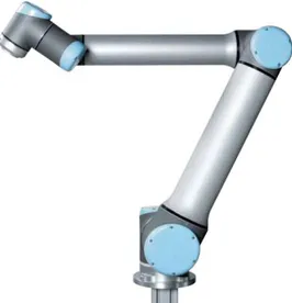
During the last few years, digital acquisition of historic cartographic material has undergone a strong evolution, strictly related to the technological and instrumental development. Thereby, the use of mechanical tools from the robotic field is by now a suitable procedure for the demands of conservation and valorisation of the historical cartographic heritage. For this reason, during this research project we decided to test the applicability and the accuracies achievable using a robotic arm - UR10 (Fig. 1) - kindly provided by the Venetian company WebbRobotica s.r.l. (URL 1). The arm used for this project is produced by a Danish company, "Universal Robots", its weigh is 29 kg, it can lift up a maximum weigh of 10 kg and it has a 1.3 meters range extension around its base.
Figure 1. The UR 10 Robotic Arm.
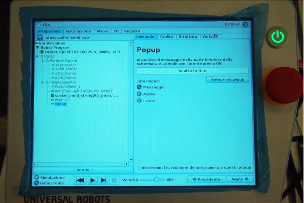
The UR robots are also composed of a touch screen with a graphic user interface (Fig. 2), a control unit and software with all the existing functionality and functions. Thanks to the touch screen, the graphic user interface allows to easily set up the arm; therefore, it can be approached even by non-expert users, and it is interesting for applications that are not part of the field in which they are traditionally used (URL 2).
Figure 2. The graphic user interface and the program implemented.
The graphic user interface, PolyScope, allows to interact with the robot and to upload existing programs or to set up new ones directly from the touch screen connected to the arm. The software can be used at different levels, selecting pre-set up functions directly from the interface or modifying them in order to better apply them to different contexts.
The program
The program implemented for the robotic arm was conceived to acquire high-resolution images of an object following a regular grid, keeping the camera’s attitude constant and shifting it by predefined movements. This characteristic is quite important, as the regular geometry of the shoots simplifies the matching phase, that is the identification of the matching points among different photographs.
In fact, when two images geometrically differ only by a translation, a cross-correlation coefficient is enough to compute the correspondences between the two images. Otherwise, the second image would need to be properly transformed (through a transformation comparable to the affine) in order to be similar to the first one. In this case, the system would not be linear and we would have to use a least square matching.
Therefore, for this program we used a function that was already codified in the PolyScope interface. This function allows the identification of a parallel plane in the arm’s reference system (which has its centre in the robot’s base) and allows us to move the acquisition sensor along that plane, keeping constant the distance from the object we have to acquire.
Moreover, the robot’s software can identify the position of the four vertexes of this pattern in three different ways: the first one is completely manual, as the user physically moves the arm, the
e-Perimetron, Vol. 10, No. 1, 2015 [21-29] www.e-perimetron.org | ISSN 1790-3769
of the final position of the arm knowing the angles of each joint; the second one calculates those angles starting from the X, Y, Z coordinates of the desired position. In this case, both these calculation are automatically made by the software, which makes it much easier for the final user. Every time the arm reaches a station point, the program acquires the position and attitude of the TCP. The TCP, or Tool Center Point, is a virtual spot located at the far end of the arm that plays an important role among the functions of the arm itself. The default position of the tool is at the centre of the flange, but – as it is just “virtual” – any user can modify it according to his needs. In fact, when used in the robotic field, the user has to take into account the different dimensions of the tools that could be attached to it and therefore modify its movements. Here, the TCP has been shifted in order to make it coincide with the approximate position of the projection centre of the camera.
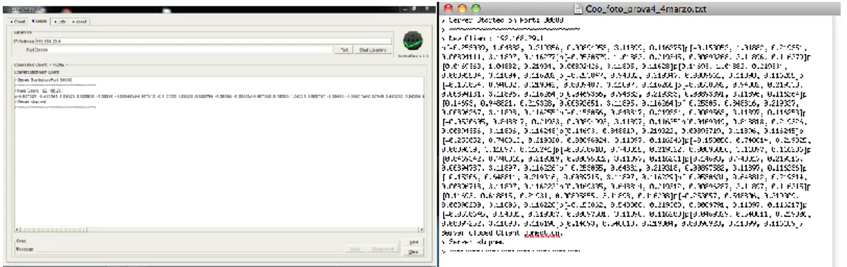
Finally, thanks to an Ethernet connection that linked the control unit to a laptop computer we were able to send the coordinates of the projection centres of each image acquired as a string of data. Therefore, the program implemented moved the arm following a regular pattern defined by the user, it acquired the coordinates of each station point inside the arm’s reference system, it sent it to the user’s laptop and waited for the operator to take the picture and click the OK button to move to the following position. The coordinates could easily be saved on the laptop as a text file at the end of the process (Fig. 3).
Figure 3. Recorded coordinates.
The arm could also move along circular trajectories around an object, allowing therefore the acquisition of images and three-dimensional data of all-round objects. However, we believed that this second operative method did not match the needs of the case study analysed, which was the automatic acquisition of the geometric and radiometric information of large and medium size historical maps.
The test
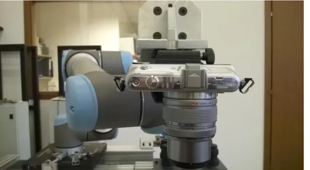
For the tests performed with the robotic arm UR10, an Olympus Pen Mini E-PM1 camera was used (Fig. 4). This camera has a sensor Live MOS 4/3” (17.3x13.0 mm), with a resolution of 4032x2688 pixels, and a pixel dimension of 0.0043 mm (URL 3). On the camera we used a zoom lens Olympus M. ZUIKO Digital, which allows obtaining a focal length in a range from 14 to 42 mm (equivalent focal length: 28 – 84 mm).
Figure 4. The camera used for the tests on the UR10.
For these tests we used a 14 mm focal length and we defined a test area of 26x43 cm. In this way, the distance from the plane, together with the number of shootings acquired, allowed covering an area larger than the whole map (42x60 cm), guaranteeing the acquisition of its borders from at least two different photograms. In fact, the reconstruction of three-dimensional coordinates for each point is possible just if the same point is acquired by two different images.
Along the short side of the map (X axis in the arm’s reference system) we planned four station points, in order to obtain a distance of 6.5 cm between each projection centre. Along the other side (Y) we planned six points, guaranteeing a distance of 7 cm.
Considering the mean distance between the camera and the map (around 35 cm) and the characteristics of the camera itself, the settings defined above allowed us to cover a surface of 0.432x0.325 m, with a pixel dimension of 0.0001 m and an 85% overlap along the X axis and 79% along the Y axis (Fig. 5).
Figure 5. Acquisition process.
e-Perimetron, Vol. 10, No. 1, 2015 [21-29] www.e-perimetron.org | ISSN 1790-3769
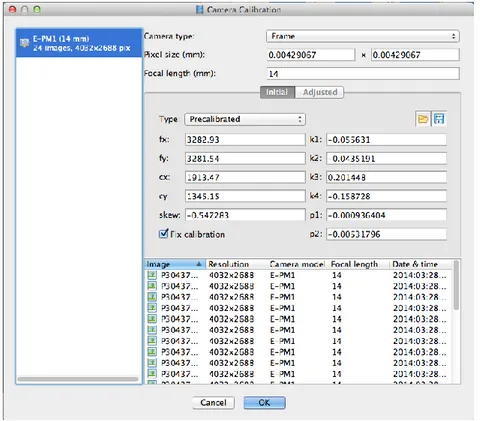
returns the focal distance, the position of the principal point, and the parameters to model both radial and tangential distortions (Fig. 6). Calibrating the camera appeared to be an essential step for the tests, as the geometry of the captures clearly was not good enough for the software to calculate the interior orientation parameters with a self-calibration. The model resulting from the project that did not use the pre-calibrated camera showed some clear deformations that did not reflect the real geometry of the object.
Figure 6. The inner orientation parameters calculated by Lens and imported into PhotoScan.
As already stated, thanks to the program implemented, the robotic arm’s software calculated the coordinates of the projection centre (X0, Y0, Z0), and the three rotation angles around the three axes (w, f, k) in the arm’s reference system, which correspond to the six parameters of the exterior orientation. Having both interior and exterior orientation, the collinearity equation can be solved: with the right overlapping between photographs it is possible to reconstruct the three-dimensional model at the correct scale.
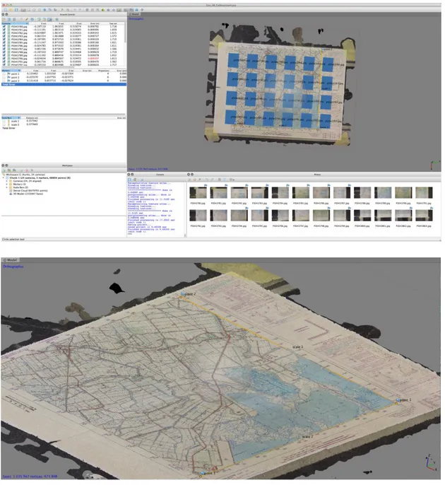
Therefore, we imported into PhotoScan both the coordinates and attitudes of the projection centres and the inner orientation parameters, in order to create a mesh model of more that one million of polygons then texturized from the same pictures (Fig. 7).
At the beginning of the test, two control distances were measured on the original map (with millimetric precision), in order to compare them to the corresponding ones on the digital model. The results were considered optimal, as the reference values and those obtained from PhotoScan coincided up to the millimetre.
Figure 7. The final model created by PhotoScan.
Moreover, PhotoScan uses the coordinates of the projection centres just as approximate initial values, in order to facilitate the matching phase. Therefore, it returns the estimation of attitudes and positions calculated, with the corresponding errors. In the tests performed, the differences between positions calculated by the robotic arm and those estimated by the photogrammetric software were around a few tenth of a millimetre. The highest errors (above 5 tenth of a millimetre) were located at the borders of the photogrammetric block, which most likely are subject to deformations. In order to avoid this phenomenon, it is probably advisable to strengthen the system through the acquisition of larger images, capturing a bigger portion of the map.
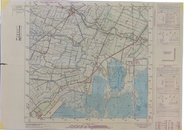
The tests performed demonstrated that we could obtain three-dimensional models with accuracy around the tenth of a millimetre in an almost automatic way (Fig. 8).
e-Perimetron, Vol. 10, No. 1, 2015 [21-29] www.e-perimetron.org | ISSN 1790-3769
Figure 8. The final orthophoto.
Conclusions and future perspectives
New digital technologies are nowadays a permeating and across-the-board phenomenon, which is penetrating into very different disciplines and fields.
Robotic arms have become very common tools in the industrial sector and, more recently, in the digital fabrication for architecture and design. Here, applied in the 3D digitization of cartographic heritage items, the technology showed some problems connected mainly to the structure of the arm itself: its heavy weight makes it an unmovable system and does not allow using it in different location. Also, its range of action (1.3m) is not suitable for the acquisition of maps with a dimension larger than 1.5 m.
Nonetheless, the possibility of lifting heavy payloads allows using also reflex or even metric cameras. This characteristic makes this system very suitable for photogrammetric purposes and for the acquisition of maps with different formats. Moreover, the automatic procedure simplifies the acquisition process and at the same time it allows obtaining high accuracy results. Also, the robotic arm’s software has a user friendly interface, which simplifies both its use and its programming.
Finally, one of the future developments could focus on the implementation of a software product able to unify the whole process, from the image acquisition to the final model, and to automatically mosaic two-dimensional objects.
Bibliography
Adami A., Fregonese L., Guerra F., Livieratos E., Tsioukas V., (2007). Digital Representations And Analysis Of Deformations Induced In Map Supporting Materials, Proc. of CIPA-2007 International Symposium, Athens, Greece, Oct. 1-6. 2007.
Ballarin M., Vernier P., (2014), Digitization of maps belonging to cultural heritage, in e-Perimetron, Vol. 9, no.4, pp. 196-205.
Daniil M., Tsioukas V., Papadopoulos K., Livieratos E., (2003). Scanning options and choices in digitizing historic maps, in New perspectives to save cultural heritage, CIPA, WG 4–Digital image processing, XIX International Symposium, Antalya, 30 Sept.-4 Oct. 2003.
Tsioukas V., Daniil M., (2009). 3D digitization of historical maps, e-Perimetron, Vol. 4, No. 1: 45-52.
Tsioukas V., Koussoulakou A., Pazarli M., Ploutoglou N., Daniil M., Stergiopoulou I. (2012). Scanning or digitizing in libraries? A test on the efficiency of dedicated book-scanning devices in digitizing bound atlases and maps, e-Perimetron, Vol. 7, No. 4: 163-169.
URL 1: http://www.webbrobotica.it/
URL 2: http://www.universal-robots.com/
URL 3: http://www.dpreview.com/reviews/olympusepm1