Schiume metalliche
Mechanical characterization of Aisi 316 tubes
filled with Al alloy foams
g. costanza, A. sili, M.E.tata
g. costanza, M.E.tata
Dipartimento di Ingegneria Industriale, Università di Roma - Tor Vergata
A. sili
Dipartimento di Ingegneria Elettronica, Chimica e Ingegneria Industriale, Università di Messina
In tubular elements filled with metal foams the structural collapse is delayed in comparison with the empty tubes, consequently compression strength and absorbed energy increase. Production methods of foams are crucial, as
they determine cellular morphology and bonds formation with tube wall. In this work AISI 316 steel tubes filled with foam of commercially pure Al and Al-Si alloys with hypoeutectic compositions were produced. The process
parameters were optimized to obtain closed cells foams with an acceptable morphology of porosity and good mechanical properties. Foams were characterized by optical and scanning electron microscopy and by computer
tomography; mechanical properties were investigated by axial compression tests (performed on foam samples and on Cu tubes, empty or filled with foams) and radial compression “Brazilian test” (carried out on AISI 316
tubes, empty or filled with foams).
Keywords: Aluminum foams - Metallography - Mechanical Testing - Non-destructive testing - Processes
intRoduction
In the automotive industry particular attention has been oriented to the utilization of structural elements as energy absorbers, in order to guarantee good passenger protection by transforming, in the event of collision, kinetic energy in deformation energy [1]. Cellular materials, as metal foams, light and high energy absorber, are very attractive in au-tomotive applications where crashworthiness, fuel saving and CO2 emission restraint are critical parameters [2]. In recent years, aluminum foams have been widely used thanks to their low density and melting point which facili-tate production process [3]. Their porous structure allows to absorb significant amounts of energy at constant and relatively low stress; in particular compression behavior is affected by cells morphology, as quoted in literature through experimental surveys [4,5] and numerical simu-lation [6]. Strain rate is critical for compression behavior of foams [7]: in quasi-static conditions, the compression diagram of a closed-cell Al foam is characterized by a short initial elastic phase, a broad plateau of plastic deformation (up to strain around 50-60%), with the gradual
disappea-rance of cells of greater diameter, and a final stage with a sudden load increase due to cells collapse in the whole sample [8]. Compression properties, such as elastic modu-lus, plastic plateau wideness and related absorbed energy depends on the collapse mode of cells [9, 10], which are affected by production process parameters [11]. In this field computer tomography has been experimented as a useful tool for observing, step by step, compression of a single sample [8].
Metallic tubes filled with Al foam cores are attractive because of the interaction between tube wall and foam which delays the structural collapse and increases ener-gy absorption during compression or bending [12]. The efforts of many researchers have been directed towards the optimization of foaming conditions inside tubes [13], testing the effects of such filling on impact energy absorp-tion in structural components [14], developing numerical simulation in order to study the buckling patterns [15] and carrying out size optimization of a hollow tube acting as energy absorber, evaluating also the effects of filling [16]. During deformation of a tube filled with metal foam, the collapse mode of cells and their interaction with the con-tainer inner surface play an important role. As regards the production process, it is necessary to avoid the formation of an insulating oxide film between foam and tube internal surface: the possibility of obtaining the formation of me-tallurgical bonds through foaming in situ with appropriate precautions was experimented in [17]. A careful investiga-tion of metal foams and filled tubular elements requires the preparation of numerous specimens at different com-pression levels, in order to perform a 3D reconstruction
Memorie
during deformation of both cells structure [18] and the whole foam/tube system [19].
In a previous work [19], copper tubes filled with alumi-num foam were produced through a foaming compacted powders inside them: the axial compression behavior of these elements was studied by means of tomographic ob-servations carried out at various levels of compression. In this work AISI 316 steel tubes filled with foam of com-mercially pure Al and Al-Si hypoeutectic alloy are produced too. The first goal has been the process parameters opti-mization to obtain closed cells foams with an acceptable morphology of porosity and good mechanical properties, successively manufacturing filled tubes to be utilized as energy absorber. Foams were metallographically charac-terized by optical and scanning electron microscopy (SEM) and by computer tomography (CT); mechanical proper-ties were investigated by axial compression test on foams samples and copper tubes (empty or filled) and radial compression “Brazilian test” on AISI 316 tubes (empty or filled).
MAtERiALs And MEtHods
Foams production
Foams production was performed by compacted powders method [20]. On the basis of the process parameters de-veloped in previous work [21 - 24], foams with closed cells of AlSi hypoeutectic alloys were produced. Silicon lowers the melting point of aluminum making it closer to that of the foaming agent decomposition (465°C). Such alloying gives a remarkable increase of hardness than pure alumi-num, improving wear resistance and mechanical proper-ties in general; however, an excess of Si gives excessive fluidity making difficult to control bubbles growth; moreo-ver Si can significantly embrittle the cells walls carrying to collapse during deformation.
Commercially pure Al powder (96.6%), alone or with Al-Si12 alloy powder to obtain hypoeutectic compositions (both 44 μm average diameter), was suitable mixed with TiH2 powder as foaming agent (5 μm average diameter) and SiC powder (37 μm average diameter) to increase vi-scosity and stabilize porosity by acting on the interface metal - bubble.
The following compositions were considered: TiH2 (0.4 - 0.6 weight %), SiC (3 - 9 weight %) and metals powder (commercially pure Al, alone or together with AlSi12) to balance. These powders were carefully mixed to have a homogeneous precursor, because, especially for TiH2 par-ticles, it is a fundamental requirement for producing foams of good quality [25].
In order to obtain precursors with diameter of 15 mm and height of 10 mm, powder mixtures were compacted in a mold, by means of hydraulic press, choosing the optimum load for crushing any oxide inside powders (120 kN for commercially pure Al and 150 kN for Al-Si alloys, as a con-sequence of their greater mechanical strength). The oxide layer was removed from the precursor surface by mecha-nical abrasion, to avoid any obstacle to bubble growth
du-ring foaming. Precursors were placed inside Cu tubes or AISI 316 steel tubes: both tubes were 16 mm diameter and 1 mm thickness and were utilized as crucibles inside a fur-nace at 700°C (optimal temperature for a continuous H2 release) for 5 min (in the case of Cu tubes) or 8 min (AISI 316 tubes). Then samples were extracted from the furnace and water cooled. These combinations of process tempe-rature and time were experimented as suitable for a good compromise between melt viscosity and foam growth.
Metallographic and tomographic investigations
Samples of foams and tube sections, after appropriate me-tallographic preparation and etching with HF (0.5%), were observed by optical microscopy and SEM. Moreover, CT investigations were performed by a variable focus appara-tus (Cu filament and X-ray accelerating voltage of 225 kV), operating in the field of micro-macro focus with spatial re-solution up to 30 microns. The 2D images of tube sections were elaborated to increase contrast and brightness in or-der to highlight cells structure and foam - wall interfaces.
Compression tests
Compression tests were performed on cylindrical speci-mens of foams and tubes (empty or filled) at crosshead constant speed (2 mm/min), with a data acquisition fre-quency of 5 Hz. For safety reasons, the maximum load did not exceed 45 kN, being the load cell capacity equal to 50 kN.
Axial compression test
Axial compression tests were carried out to compare com-mercially pure Al and Al-Si alloys behaviors, excluding tube stiffening effects. Results of axial compressions on Cu tu-bes filled with Al foam, performed step by step to take tomographic images, were also reported [19].
Compression stress is given by the following equation: 1) s = 4 P / (π D2)
being P the applied load and D the specimen diameter, assumed equal to the initial value.
The deformation ε was referred to the crosshead advan-cement (δ):
2) ε = (L – Lo) / Lo = δ / Lo
where L is the length of the deformed specimen and Lo its
initial length.
Radial compression test
On steel tubes, because of their higher stiffness compa-red to copper tubes, were carried out radial compression tests, named “Brazilian test”. This test is used in the field of rocks, powder metallurgy [26] and in any case tensile test cannot be performed [27]. As shown in figure 1, it gives rise to compression stresses along the direction of compression (y) and tensile stresses along the perpendi-cular direction (x).
Schiume metalliche
The compression (sy) and tensile (sx) stresses along the y axis achieve their maximum values at the origin and assu-me the following expressions [27]:
3) sy = - 6 P / (π D l)
sx = 2 P / (π D l)
where l is the axial length of the specimen and D is assu-med equal to the initial diameter.
Deformation values were calculated on the basis of the diameter values along the direction of compression accor-ding to the following expression:
4) ε = (Do – D) / Do being Do the initial diameter.
Fig. 1 - Sketch of the radial compression test “Brazilian test”: y compression stress and x tensile stress directions.
Fig. 1 - Schema della prova di compressione radiale “Brazilian test”: y direzione degli sforzi di compressione, x direzione degli sforzi di trazione.
REsuLts And discussion
Process parameters optimization
The best quality of cells morphology was achieved with commercial pure Al: samples of AISI 316 tube and Cu tube filled with commercially pure Al are shown in fig. 2, where the CT image appears suitable to check the bonding con-ditions between foam and tube wall.
The AlSi6 and AlSi8 foams had good quality, even if some problems of cells coalescence were encountered. Figure 3 shows three samples of AlSi6 alloy, with 0.4% of TiH2 and different concentrations of SiC. The SiC particles have the dual effect of increasing liquid viscosity and stabilize porosity: Banhart’s work shows how improvements can be achieved by stabilizing bubbles growth during foaming [29]. In our experiments the optimal content of the stabili-zer agent SiC resulted equal to 9%, greater than the quan-tity of 3% utilized for pure Al foam, while the blowing agent content was the same (0.4% of TiH2).
About the Si content in the matrix, the best result in terms of cell morphology (size, shape and regular distribution) was obtained with the AlSi8 alloy, while other composi-tions had problems of cells coalescence. In any case these problems are common to all the AlSi alloys, due to higher foaming time in the steel crucible.
In figure 4 two samples of AlSi8 foams with two different content of the blowing agent TiH2 are shown: titanium
Fig. 2 - Samples of tubes filled with commercially pure Al foam: a) steel tube (photographic image of a section), b) Cu tube (CT image).
Fig. 2 – Campioni di tubi riempiti con schiuma in Al commercialmente puro: a) tubo di acciaio (immagine fotografica del tubo sezionato), b) tubo di rame (immagine tomografica).
Fig. 3 – Effect of SiC content on foaming process (AlSi6 alloy – TiH2 0.4%): a) 3%, b) 9%, c) 12%.
Fig. 3 – Effetto del tenore di SiC sul processo di schiumatura (lega AlSi6 – TiH2 0.4%): a) 3%, b) 9%, c) 12%.
hydride begins to dissociate above 465°C, giving rise to bubbles of H2 and causing the molten metal expansion and the consequent filling of the crucible.
The TiH2 and SiC contents determine density and, accor-ding to the cooling conditions, cells size: the best cell mor-phology was obtained with a TiH2 content equal to 0.4%.
Fig. 4 – Effects of TiH2 content on foaming process (AlSi8 – SiC 9%): a) 0.4%, b) 0.6%.
Fig. 4 – Effetto del tenore di TiH2 sul processo di schiumatura (lega AlSi8 – SiC 9%): a) 0.4 %, b) 0.6%.
Memorie
Metallographic investigations
Metallographic investigations confirmed the hypoeutectic alloy formation. Due to the high melting point, the SiC par-ticles are dispersed in the metal matrix and are perfectly visible at low magnification (fig. 5a). The metal matrix has a hypoeutectic morphology with primary Al grains and Si precipitates at their boundary, clearly recognizable at hi-gher magnification (fig. 5b). The Si particles have average dimension of about 1 μm (fig. 6).
Compression test
The compression curves of three foam samples (commer-cially pure Al, AlSi6 and AlSi8), not contained in tubes, are compared in figure 7: both compression strength and ab-sorbed energy increase with the Si content. The Al foam has a progressive strain hardening according to deforma-tion. Instead the AlSi alloys curves are characterized by an initial peak, followed by stress reductions at deformations above 20%, ascribed to cells collapse due to the alloy brit-tleness, or other factors such as polyhedral shape cavities that give rise to a triaxial stress state. In all the examined cases, at deformations around 80%, stress increases shar-ply as a result of the generalized cells collapse.
At the end of compression test, the Al foam deformed into a thin homogeneous disk, while the AlSi ones show some fractures that can be ascribed to crack nucleation caused by the combined effects of SiC sharp edges and alloy brit-tleness.
Cu tubes filled with commercially pure Al foam have a stif-fness significantly greater than those of empty tubes, as shown in figure 8 [19]. Their compression behavior is cha-racterized by a sequence of peaks, each one correspon-ding to wall buckling.
Cu tube filled with Al foam started buckling with the first two folds located at the two ends of the sample, while the third fold grows at half height; instead the empty tube started to buckle at one of the two ends and continues sequentially. During the initial stage of deformation (fig. 9a), the cells remain intact and adherent to the tube wall, with localized detachments at the first fold or at the zones where folds are to be formed. At successive deformation step (fig. 9b) cells appear strongly damaged with evident detachment from tube walls.
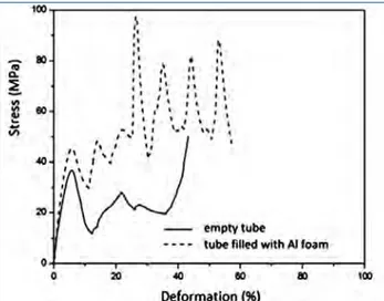
Radial compression curves of the AISI 316 tubes, respec-tively empty and filled with commercially pure Al or AlSi8 alloy foams, are shown in figure 10. All the three diagrams show a wide plateau of plastic deformation. In general foam increases the tube stiffness, anyway the AlSi8 foam is more performing in terms of mechanical strength and absorbed energy, although Si entails a weight increase.
concLusions
Conclusions are drawn with reference to the following to-pics: foaming parameter optimization, metallurgical and mechanical characterization of foams, mechanical beha-vior of tubes filled with foam. Regarding the first point,
Fig. 5 – Optical micrographs of AlSi6 foam: a) cell wall with SiC particles, b) detail of metal matrix.
Fig. 5 – Micrografie ottiche di una schiuma in lega AlSi6: a) parete di una cellula con evidenza delle particelle di SiC, b)
dettaglio della matrice metallica.
Fig. 6 – SEM micrograph of AlSi6 foam.
Fig. 6 – Micrografia SEM di una schiuma in lega AlSi6.
Fig. 7 – Compression diagrams: commercially pure Al and AlSi alloys foams.
Fig. 7 – Diagrammi di compressione: schiume in Al commercialmente puro e leghe AlSi.
Schiume metalliche
Fig. 8 – Compression diagrams: empty Cu tube, Cu tube filled with commercially pure Al.
Fig. 8 – Diagrammi di compressione: tubo di Cu vuoto, tubo di Cu riempito con schiuma in Al commercialmente puro.
Fig. 9 – Tomographic sections at two deformation steps of a Cu samples filled with Al foam: a) initial deformation stage; b) after deformation (50%).
Fig. 9 – Sezioni tomografiche a due livelli di deformazione di un tubo di rame riempito con schiuma in alluminio: a) fase iniziale della deformazione; b) fase avanzata (50%).
a) b)
Fig. 10 – Radial compression “Brazilian test” results (compression stress according to diametral
deformation)
Fig. 10 – Risultati della prova di compressione radiale “Brazilian test” (sforzi di compressione in funzione della
deformazione diametrale).
commercially pure Al and AlSi alloy foams of good quality were obtained starting from compacted powders, thanks to the optimization of blowing and stabilizer agents con-tents according to process time and temperature. Commercial pure Al foams showed the best morphology quality of cells; the AlSi6 and AlSi8 foams had a good qua-lity too, even if some problems of cells coalescence were encountered. Greater compression strength and absorbed energy were achieved testing the AlSi hypoeutectic alloys, in particular both the two properties increased if the Si content changed from 6 to 8 %.
Finally it was experimented that compression strength and absorbed energy of Cu and AISI 316 tubes filled with foams are significantly greater than those of empty tubes. During axial compression, Cu tubes showed characteristic buc-kling folds and related peaks in the stress - strain curve; instead the AISI 316 tubes, tested by radial compression, gave continuous curves.
AcKnoWLEdgEMEnts
we would like to thank Mr. Piero Plini and Mr. Benedetto Iacovone for technical support during mechanical testing; Dr. Francesco Brugnolo and Dr. Livio Longobardi, who con-tributed actively to this research carrying out their thesis.
REfEREncEs
1] G. Dong, D. wang, J. Zhang, S. Huang, “Side Structure Sensitivity to Passenger Car Crashworthiness During Pole Side Impact”, Tsinghua Science and Technology, 12(3) (2007). 290-295
2] G. Lu and T. Yu, “Energy absorption of structures and materials”, woodhead Publishing Limited, Cambridge, Uk, (2003), 1–424
3] M. Yu, J. Banhart, “Mechanical properties of metal foams”, in Metal Foams, Ed. J. Banhart and H. Eifert, Verlag MIT, Bremen (1998), 37-48
4] H. Yu, Z. Guo, Bing Li, G. Yao, H. Luo, Y. Liu, “Research into the effect of cell diameter of aluminium foam on its compressive and energy absorption properties”, Material Science and Engineering A, 454-455 (2007), 542-546
5] F. Campana, D. Pillone, “Effect of wall microstructure and morphometric parameters on the crush behaviour of Al alloy foams”, Materials Science and Engineering A, 479 (2008), 58-64
6] Yang An, Cui’e wen, Peter D. Hodgson, Chunhui Yang, “Investigation of cell shape effect on the mechanical behaviour of open-cellmetal foams”, Computational
Memorie
Science, 55 (2012), 1-9
7] G. Costanza, M.E. Tata, “Dynamic and static compres-sive behaviour of aluminium foam”, Proceedings of the 4th International Structural Engineering and Construc-tion Conference, ISEC-4 - InnovaConstruc-tions in Structural En-gineering and Construction, Vol. 2 (2008) 919-922 8] G. Costanza, F. Mantineo, S. Missori, A. Sili, M.E. Tata,
“Characterization of the compressive behaviour of an Al foam by X-ray computerized tomography”, TMS 2012 - 141st Annual Meeting & Exhibition, March 11-15 2012, Orlando FL,, Light Metals 2012, Edited by Carlos E. Suarez, John wiley & Sons, pp. 533-536
9] H.w. Song, Q.J. He, J.J. Xie, A. Tobota, “Fracture me-chanisms and size effects of brittle metallic foams: in situ compression test inside SEM”, Composites Scien-ce and Technology, 68 (2008), 2441-2450
10] Y. Mu, G. Yao, L. Liang, H. Luo, G. Zu, “Deformation mechanims of closed-cell aluminium foam in compres-sion”, Scripta Materialia, 63 (2010), 629-632
11] G. Costanza, R. Montanari, M.E. Tata, “Optimisation of TiH2, and SiC content in Al foams”, La Metallurgia Ita-liana, Vol. 97 n. 6 (2005), 41-47.
12] M.Seitzberger, F.G. Rammerstorf. H.P. Degischer, R.Gradinger, “Crushing of axially compressed steel tu-bes filled with aluminium foam”, Acta Mechanica, 125 (1997), 93-105.
13] Makoto kobashi, Ryosuke Sato, Naoyuki kanetake, “Foaming and filling-in behavior of porous aluminum in hollow components”, Materials Transactions, V. 47, No 9 (2006), 2178-2182.
14] Y. An, Cui’E Gwen, P. Hodgson, C. Yang “Impact re-sponse and energy absorption of aluminum foam-filled tubes”; Applied Mechanics and Materials, V. 152-154 (2012), 436-439
15] wenyi Yan, Emilien Durif, Yasuo Yamada, Cui’e wen, “Crushing simulation of foam-filled aluminium tubes”, Materials Transactions, V. 48, No. 7 (2007), 1901-1906.
16] H.R. Zarei, M. kröger, “Optimization of the foam-filled aluminum tubes for crush box application”, Thin-wal-led Structures, 46 (2008) 214–221
17] L. Bonaccorsi, E. Proverbio, N. Raffaele. “Effect of the interface bonding on the mechanical response of alu-minium foam reinforced steel tubes”, J. Mater. Sci., 45 (2010), 1514-1522
18] N. Michailidis, F. Stergioudi, H. Omar, D.N. Tsipas, “An image-based reconstruction of the 3D geometry of an Al open-cell foam and FEM modeling of the material re-sponse”, Mechanics of Materials, 42 (2010), 142-147
19] G. Costanza, F. Mantineo, A. Sili, M.E. Tata, “Characte-rization of Cu tube filled with Al alloy foam by means of X-ray computer tomography”, TMS2014 - 143rd An-nual Meeting Supplemental Proceedings, San Diego, California (USA), February 16-20, 2014
20] J. Banhart, J. Baumeister, M. weber, Proc. of the Euro-pean Conference on Advanced PM Materials, Birming-ham, (1995), p.201
21] G. Costanza, G. Gusmano, R. Montanari, M.E. Tata, “Metodi di produzione e applicazioni delle schiume metalliche”, La Metallurgia Italiana, n. 2/2003, p. 31-35.
22] G. Costanza. G. Gusmano, R. Montanari, M.E. Tata, N. Ucciardello, “Effect of powder mix composition on Al foam morphology”, Proceedings of the Institution of Mechanical Engineers, Part L: Journal of Materials: De-sign and Applications, 222 (2008), 131-140.
23] G. Costanza, M.E. Tata, “Metal foams: Recent experi-mental results and further developments”, Metallurgia Italiana, Vol. 103 n. 3 (2011), 3-7.
24] G. Costanza, M. E. Tata, Recycling of exhaust batteries in lead-foam electrodes, in REwAS 2013 Enabling Ma-terials Resource Sustainability, Ed. Anne kvithyld and Christina Meskers, ISBN 978-1-1186-0587-5, pp . 272-278.
25] C. Park, S. R. Nutt, “Effect of process parameters on steel foam synthesis”, Materials Science and Enginee-ring, A297 (2001), 62-68
26] P. Jonsén, H.-A. Häggblad, “Fracture energy based con-stitutive models for tensile fracture of metal powder compacts”, International Journal of Solids and Struc-tures, 44 (2007), 6398–6411
27] Proveti, J. and Michot, G., 2006, The Brazilian test: a tool for measuring the toughness of a material and its brittle to ductile transition. Int. J. Fracture, 139 455-460.
28] Ye Jianhong, F.Q. wu, J.Z. Sun, “Estimation of the ten-sile elastic modulus using Brazilian disc by applying diametrically opposed concentrated loads”, Interna-tional Journal of Rock Mechanics & Mining Sciences 46 (2009) 568–576
29] J. Banhart, F. Baumgärtner, S. Cox, B. kronberg, D. Langevin, S. Odenbach, D. weaire, T. wübben, “Deve-lopment of advanced foams under microgravity”, 1st International Symposium on Microgravity Research and Applications in Physical Sciences and Biotechno-logy, 10-15 September 2000, Sorrento, Italy - Procee-dings, ESTEC/ESA Publishing Division, Noordwijk, ESA Special Publications SP-454, (2000), 589–596.