arXiv:2008.01390v1 [physics.ins-det] 4 Aug 2020
Prepared for submission to JINST
Tracker-In-Calorimeter (TIC): a calorimetric
approach to tracking gamma rays in space
experiments
O. Adriania,b G. Ambrosic P. Azzarellod A. Bastie E. Bertia,b B. Bertuccic,f G. Bigongiarie,g L. Bonechib M. Bongia,b S. Bottaib M. Brianzib P. Brogie,g G.
Castellinib,h E. Catanzanic,f C. Checchiae,g R. D’Alessandroa,b M. Durantic S. Dettib N. Finettib,i V. Formatoc,∗ M. Ionicac P. Maestroe,g F. Malettab P. S. Marrocchesie,g N. Morib,1
L. Pacinib P. Papinib S. Ricciarinib,h G. Silvestrec,f P. Spillantinib O. Starodubtsevb F. Stolzie,g J. E. Suhe,g A. Sulaje,g A. Tiberiob E. Vannuccinib
aDepartment of Physics and Astronomy, University of Florence, I-50019 Sesto Fiorentino,
Flo-rence, Italy
bINFN sezione di Firenze, I-50019 Sesto Fiorentino, Florence, Italy cINFN sezione di Perugia, I-06123 Perugia, Italy
dDépartement de Physique Nucléaire et Corpusculaire, University of Geneva, CH-1211 Geneva,
Switzerland
eINFN sezione di Pisa, I-56127 Pisa, Italy
fDepartment of Physics and Geology, University of Perugia, I-06123 Perugia, Italy
gDipartimento di Scienze Fisiche, della Terra e dellâĂŹAmbiente, University of Siena, I-53100
Siena, Italy
hIFAC-CNR, Via Madonna del Piano 10, I-50019 Sesto Fiorentino (Firenze), Italy
iDepartment of Physical and Chemical Sciences, University of LâĂŹAquila, Via Vetoio, I-67100
LâĂŹAquila, Italy
∗now at INFN sezione di Roma Tor Vergata, I-00133 Rome, Italy E-mail: [email protected]
Abstract: A multi-messenger, space-based cosmic ray detector for gamma rays and charged particles poses several design challenges due to the different instrumental requirements for the two kind of particles. Gamma-ray detection requires layers of high Z materials for photon conversion and a tracking device with a long lever arm to achieve the necessary an-gular resolution to separate point sources; on the contrary, charge measurements for atomic nuclei requires a thin detector in order to avoid unwanted fragmentation, and a shallow instrument so to maximize the geometric factor. In this paper, a novel tracking approach for gamma rays which tries to reconcile these two conflicting requirements is presented. The proposal is based on the Tracker-In-Calorimeter (TIC) design that relies on a highly-segmented calorimeter to track the incident gamma ray by sampling the lateral development of the electromagnetic shower at different depths. The effectiveness of this approach has been studied with Monte Carlo simulations and has been validated with test beam data of a detector prototype.
Contents
1 Introduction 1
2 Measurement principle 3
3 Detector design 3
4 Monte Carlo simulations 5
4.1 Track reconstruction algorithm 5
4.2 Results 7
5 Detector prototype 7
6 Test beam results 10
7 Conclusions 14
1 Introduction
A multi-messenger detector for cosmic rays, capable of detecting charged particles and gamma-ray photons, represents an appealing perspective for the next generation of space-based, high-energy direct detection experiments from both the scientific and the logistic points of view. Such a facility would provide invaluable data for various research fields, at a significantly reduced cost compared to a classic two dedicated detector solution (one for gamma rays and one for charged particles). Its design however poses many challenges. In order to make precise measurements with a good statistical significance also at high energies, scientific requirements range from good energy and tracking resolution to high geometric factor and effective area. Trying to meet all these requirements for charged particles and gamma rays with a single detector raises some inevitable conflicts.
Gamma-ray tracking is typically performed using a pair-conversion telescope. Each plane of the telescope is made of a layer of passive material (e.g. tungsten) in which the primary photon is converted into an e+-e− pair, coupled with a sensitive layer (e.g. silicon microstrip detector) which measures the impact position of the electron and the positron. Several of these planes are stacked to increase the photon conversion probability and to provide multiple position measurements along the e+-e− trajectory; from these measure-ments the track of the incident photon is reconstructed. The planes are suitably spaced apart from each other, so as to achieve the lever arm that, in combination with the spatial resolution of the position measurements, provides the required tracking resolution. This concept has been successfully implemented in recent space-borne gamma-ray detectors, like Fermi [1] and AGILE [2], and can be considered as the reference technique for gamma-ray
tracking at energies above some hundreds MeV. Being sensitive to ionization, such a device is in principle also able to track charged primary particles and is actually used in detectors for charged particles with gamma-ray detection capabilities like DAMPE [5]
On the other hand, charged particle physics requires an accurate measurement of the charge of the nuclei. The charge Z of a relativistic particle or atomic nucleus impinging on a pair-conversion telescope can be measured by exploiting the Z2
scaling of the energy deposited by ionization on the sensitive layers. However, the presence of a non-negligible amount of passive material increases the fragmentation probability of the nucleus. After fragmentation, the subsequent ionization measurements are no longer useful for charge de-termination, and typically must be rejected in offline charge reconstruction by an algorithm which identifies the interaction point. The reduced set of independent ionization measure-ments and the limited accuracy of the algorithm likely lead to a worsening of the charge identification performance. The simplest solution to this problem is to add a dedicated sub-detector for charge measurement externally to the pair-conversion telescope, for example a set of silicon detectors with a minimal amount of passive material. In this way the charge can be precisely measured before the nucleus traverses a considerable amount of material, at the price of an increase in power consumption and cost.
Such a configuration consisting of a charge detector on top of a pair-conversion telescope can provide robust performance for both charge identification and tracking of gamma rays and charged particles, but it will have an important impact on the overall geometric factor of the instrument. The ability to resolve point sources with the desired accuracy requires a good tracking resolution, that translates into a high lever arm value for the tracking telescope (since at fixed resolution of position measurement the angular resolution scales as 1/L, where L is the distance between the outmost tracking layers); stacking the charge detector on top of the telescope further increases the overall height of the instrument. This results in a reduction of the field of view and so in a degradation of the geometric factor, since for a particle telescope with a distance d between the entrance and exit planes defining the instrument acceptance the geometric factor scales approximately as 1/d2
[3]. This fact will impair the possibility to detect a sufficient amount of high-energy particles, effectively limiting the energy range covered by the instrument.
The weight of the pair-conversion telescope can also have a detrimental impact on detector design. The mass budget of a space experiment is usually severely constrained, limiting the maximum weight and dimension of the calorimeter and thus the overall geo-metric factor. Allocating a significant fraction of this budget to the passive material needed for the conversion of the gamma rays further reduces the instrument performance.
In this paper, an alternative detector design named Tracker-In-Calorimeter (TIC) aimed at mitigating the issues described above is presented, together with expected per-formance. Section 2 describes the measurement principle; section 3 gives an example of a realistic detector design implementing the measurement principle; section 4 shows the ex-pected performance for a full-scale detector obtained with Monte Carlo simulations, while section 5 illustrates the design of a detector prototype. The results obtained using data from the prototype acquired at test beams are presented in section 6.
2 Measurement principle
The basic idea is to use a calorimeter as a tracking device for gamma rays. It relies on the fact that most cosmic-ray detectors feature an electromagnetic calorimeter below the main tracking device, with the main purpose of measuring the particle energy and discriminating electrons and protons by means of topological shower analysis. Indeed, the effort towards the high-energy frontier in space (sub-TeV for gamma rays, multi-TeV for electrons and PeV for hadrons) is being pursued by running [4, 5] and future [6] experiments mainly with deep, homogenous electromagnetic calorimeters with scintillating crystals. When a photon hits the calorimeter it generates an electromagnetic shower, whose axis preserves the information about its direction. By sampling the transverse profile of the shower at different depths in the calorimeter it is possible to reconstruct the photon direction, e.g. by computing the center-of-gravity of the shower image on each layer and then fitting with a line. The accuracy and precision of this method can be improved by more sophisticated reconstruction algorithms and also by a more refined lateral sampling.
This tracking principle has already been implemented by other experiments, obtaining resolutions better than about 100 µm on the reconstructed impact point for electrons above 100 GeV using a Si-W sampling calorimeter [7]. Since the track reconstruction procedure relies completely on the development of an electromagnetic shower, similar performance can be expected for photons. A successful application of this method to the calorimetric section of a cosmic-ray detector would allow to offload the gamma-ray tracking duties to the calorimeter, optimising the tracker design for the tracking and possible charge measurement of primary nuclei and electrons. In practice, it would be possible to remove the passive material from the main tracker and also to reduce the overall height of the instrument (since tracking requirements for gamma rays are usually more demanding than those for charged particles due to the necessity to identify point sources), thus providing a solution to most of the issues described in section1.
3 Detector design
This proposal for a realistic configuration of a tracking calorimeter for a future multi-messenger cosmic-ray experiment starts by considering the innovative proposal for a homo-geneous and isotropic calorimeter made by the CaloCube collaboration [8, 9]. The main feature of this calorimeter is to be able to accept particles not only from the face point-ing towards the zenith but also from lateral faces, thus boostpoint-ing the geometric factor by a theoretical 5x factor in the same mass and power consumption envelope. This design has been chosen with some modifications for the future HERD experiment [6], and thus constitutes an appealing starting point. The CaloCube sensitive elements are cubic scin-tillating crystal of size 1 Molière radius read out by two photodiodes of different sizes in order to achieve a high dynamic range. The crystals are arranged in a cubic 3D mesh. Such a segmented calorimeter already provides sizeable information about the development of the electromagnetic shower, that can be further enhanced by instrumenting one side (e.g. the zenithal one) with silicon microstrip detectors interleaved with the first layers of
scintillating crystals, as schematically shown in figure 1. Going from top to bottom, the upper layers are made of thin crystals rather than cubic crystals, and a gap is left between the first two silicon detectors. This arrangement reduces the crystal material traversed by the e+-e− generated by photon conversion before hitting the precise silicon sensors, miti-gating the impact of multiple scattering on the tracking performance. In addition to this, the small gap allows for having two consecutive position measurements by silicon detectors without material in between, further reducing the multiple scattering effects. The two sub-sequent layers of crystals are made of thin elements as well, providing a limited amount of material for shower development between other precise position measurements. Then the basic CaloCube design made of cubic scintillators is restored. The silicon detectors sample the lateral development of the early stage of electromagnetic showers originating in the crystals at different depths in the calorimeter with a sampling interval of the transverse positions much smaller than that of crystals (typically hundreds of µm against some cm). This fine-grained information is crucial in improving the track reconstruction performance. A similar approach has been adopted in [7], where silicon detectors are interleaved with tungsten plates to build a sampling calorimeter with tracking capabilities. The novelty in this proposal is the use of an active material as gamma-ray converter to maximize the energy resolution.
L
Thin
crystals
Cubic
crystals
Si
detectors
.
.
.
.
.
.
.
.
.
. . .
. . .
. . .
. . .
. . .
. . .
Figure 1. Side view of a portion of the tracking calorimeter. The first 3 scintillator layers on top are made of thin crystals (blue) and interleaved with 4 silicon microstrip layers (orange). Cubic crystals (cyan) are used below this top structure.
4 Monte Carlo simulations
To quantitatively assess the expected performance of the tracking calorimeter proposed in the previous section, a FLUKA [10,11] Monte Carlo simulation has been set up. The simu-lated detector is modeled adopting some of the design choices of the future HERD calorime-ter [6] (which in turn follows in many aspects the CaloCube design described in section3): the thin and cubic crystals are made of Lutetium Yttrium Orthosilicate (Lu2SiO5), com-monly known as LYSO, and the cubes have side 3 cm while the thin scintillators are 1.5 cm (i.e. half-cube) thick. The simulated geometry is implemented after that depicted in figure
1. The whole calorimeter is a 21x21x21 mesh of cubic crystals, with the silicon layers and thin crystals stacked atop the top face. The gap L between the first two silicon detectors is 7 cm, while the inter-crystal gaps are 5 mm. The total depth along the up-down direction is ∼ 3.2 nuclear interaction lengths (λI) and ∼ 58 radiation lengths (X0). The thickness and readout pitch for silicon detectors are set to 300 µm and 50 µm, respectively. The gaps between the cubes are filled with carbon fiber, to mimic the presence of a support structure; no other supports are present.
The simulated input spectra consist of monochromatic gamma rays at different energies (1, 10 and 100 GeV), with an isotropic angular distribution and a zenith angle for the initial direction limited in the ± 30◦ region around the zenith direction. The starting point is sampled from a flat surface just above the first layer of thin crystals, so that the whole top face is uniformly illuminated by incoming photons.
4.1 Track reconstruction algorithm
The estimator of the incident particle track is an iterative algorithm based on all the information obtained by the calorimeter signals (both crystals and Si detectors). The key point is that the energy of the primary photon is well known thanks to the calorimetric measurement, therefore all the parameters of the algorithm, which to a certain extent can depend on the energy, can be considered known within the energy resolution of the instrument.
The Principal Component Analysis method (PCA) has been used for the iterative track reconstruction algorithm. The first step is based on the crystal signals only, without using the silicon detector information. Let N be the total number of crystals with signal above a given threshold, then the three-dimensional covariance matrix of the crystal coordinates c(n)
i (with i = X, Y, Z and n = 1, . . . , N) weighted with the signal amplitude is:
MC AL i j = 1 ÍN n=1WC AL(n) N Õ n=1 W(n) C AL(c (n) i − Ci)(c (n) j − Cj), (4.1)
where WC AL(n) is the assigned weight of the n-th crystal (equal to the signal SC AL(n) on the n-th crystal) and Ci is the center of the distribution of the signals defined by:
Ci = ÍN n=1WC AL(n) c (n) i ÍN n=1WC AL(n) . (4.2)
As a first step, the eigenvector with the largest eigenvalue of the covariance matrix MC AL
i j is considered as estimator of the primary track. The next step is to consider the energy deposits in the silicon detectors. At a given depth Z, a silicon micro-strip detector measures only one coordinate (X or Y ), and to measure both typically two parallel detector planes arranged with perpendicular segmentation directions are used. For this reason, the silicon measurements along the two segmentation directions are used to independently reconstruct the two projections of the track on the X − Z and Y − Z views, and from these projections the track in the three-dimensional space is then obtained. In the following the procedure for X − Z is described, the one for Y − Z being the same.
Let J be the total number of strip with signal above threshold and with di(k) (with i = X, Z) denote the coordinate of the k-th strip. The bidimensional covariance matrix for the PCA method is expressed by:
MSI L i j = 1 ÍJ k=1W (k) SI L J Õ k=1 W(k) SI L(d (k) i − Di)(d (k) j − Dj), (4.3)
where WSI L(k) is the weight for the k-th silicon readout channel, and with the centre of the distribution of the signals defined by:
Di = ÍJ k=1WSI L(k) d (k) i ÍJ k=1W (k) SI L . (4.4)
To improve the angular resolution, particular care must be taken in defining the weight W(k)
SI L. In the algorithm used for this work, W (k)
SI L depends on the detector plane P (with P ranging from 1 to the number of silicon planes) to which the strip belongs.
Once a previous estimate of the particle track (in this case, the track obtained using only the crystal signals) is available, it can be affirmed that the spatial dispersion for the X coordinate of its intersection in the P-th plane can be approximated by a Gaussian function. The standard deviation σP can be estimated by simulation. The weighting factor is then defined by: W(k) SI L = S(k) SP × 1 √ 2πσP exp −1 2 d(k) i − XP σP !2 , (4.5)
where XP is the intersection of the track on the P-th plane given by the previous estima-tion, S(k) is the signal of the k-th strip and SP is the total signal measured by the P-th silicon plane. The reason for the introduction of SP in the denominator is that the angular dispersion in the development of the electromagnetic shower increases going deeper into the calorimeter due to multiple scattering. Because the SP value increases as the amount of material crossed, the signals of silicon planes that lie deeper are weighed to a lesser extent. The track reconstruction algorithm by means of the silicon detector signals uses the PCA method with the covariance matrix MSI L
i j . Since this new estimate depends on the previous one through the value of WSI L(k) , it can be repeated by using the new estimate as the previous one until convergence.
4.2 Results
The angular resolution has been computed for simulated photons that convert into an e+-e− pair in the first thin crystal, thus producing a well-developed shower in the silicon detectors. The conversion efficiency in this case is ∼ 65%. The resolution can be improved by selecting only those events for which the tracking algorithm converged within a given number of iterative steps, reducing at the same time the overall efficiency. This is an effective method to select “golden samples” of well-reconstructed events in offline analysis, and for tuning the accuracy according to the needed total statistics. The resolution as a function of the overall efficiency (conversion and selection) for 10 GeV photons is shown in figure 2. The TIC efficiency is the combined (conversion and selection) efficiency, and tops at 65% for 100% selection efficiency. This can be regarded as an overestimation of the real overall efficiency since other important factors are not considered in this estimate. For example, the trigger is expected to have a sizeable impact, but for implementing a realistic trigger a more refined instrument design is needed, which would reasonably include other sub-detectors (like an anticoincidence shield) which are unrelated to the problem of tracking gamma rays; so this aspect is neglected in this study. For Fermi and DAMPE the efficiency has been estimated by dividing the effective areas quoted in [13] and [5] by the geometrical areas of the two instruments (a whole tracker plane for Fermi and the upper face of the BGO calorimeter for DAMPE). At this energy the resolution of TIC is worse than Fermi (total) for the same efficiency of ∼ 36% but can match Fermi by reducing the efficiency to ∼ 14%, and is generally better than DAMPE.
The performance of the tracking algorithm applied to the simulated data as a function of the gamma ray energy is compared to those of Fermi and DAMPE in figure3. The general trend is a performance improvement with increasing energy, which is more pronounced than that of Fermi and DAMPE and that provides considerably better performance above some ten GeV. In order to understand this behavior it is useful to consider the limiting factors for the angular resolution at different energies. In the GeV region the tracking precision is mainly limited by multiple scattering for both the pair conversion telescopes and TIC, the latter having thicker converters and thus worse performance. As the energy increases the multiple scattering becomes less relevant and the pair conversion telescopes start to get limited by the position resolution of their tracking systems, so that the tracking performance initially improves and then reaches a plateau. On the contrary, the electromagnetic showers in TIC become more populated and less affected by statistical fluctuations, so that the precision of the position measurements of the transverse profile continues to improve with increasing energy, and also does the tracking precision. At 100 GeV the performance is better than Fermi and DAMPE, with comparable or better efficiency.
5 Detector prototype
To validate the measurement principle and the simulation results, a small-scale prototype of the tracking calorimeter was built and tested with particle beams. The idea behind this test was to compare the results obtained with real data with those obtained from a Monte Carlo simulation of the prototype detector, in order to assess the validity of the full-scale
0 0.1 0.2 0.3 0.4 0.5 0.6 0.7 Efficiency 0 0.05 0.1 0.15 0.2 0.25 0.3 0.35 0.4 ) ° Angular resolution (68%) ( TIC incidence ° DAMPE 30
DAMPE normal incidence Fermi front
Fermi total
Figure 2. Angular resolution of TIC for 10 GeV photons as a function of the conversion+selection efficiency, compared to Fermi [13] and DAMPE [5].
simulation results described in section 4. In order to reduce the construction costs, the detector was built by refurbishing the CaloCube prototype [9] with additional layers of thin crystals obtained by sawing some spare CaloCube cubic scintillators, and with spare one-sided silicon microstrip detectors from the DAMPE experiment [12].
The CaloCube crystals are made of CsI(Tl), which is a different material from the LYSO used for the full-scale simulations described in section 4. For this reason, and also for the different sizes of the full-scale detector and the prototype, test beam data have to be compared to a dedicated simulation of the prototype detector and not to the full-scale simulation. The dynamic range required for the readout of the thin scintillators is narrower than that for cubic ones, since the former are less thick than the latter and are placed on the external part of the instrument where the electromagnetic showers just start to develop; hence a lower amount of scintillation photons with respect to the cubes is expected in thin elements. For this reason only the large-area Excelitas VTH2090 photodiode of the high-dynamic-range, dual-photodiode readout of CaloCube has been used for thin crystals. The DAMPE silicon sensors were arranged in modules with two silicon wafers put side by side along the strip transversal direction; each wafer is 320 µm thick, with 384 readout strips (for a total of 768 strips per module) and a readout pitch of 240 µm. A small dead area of ∼2 mm was present between the two active areas.
1 −
10 1 10 102 103
Photon energy (GeV)
2 − 10 1 − 10 1 10 ) ° Angular resolution (
TIC (eff. ~ 65%, conversion)
TIC (eff. ~ 40%, conversion + selection) Fermi total (eff. ~ 36% @ 10 GeV) Fermi front (eff. ~ 20% @ 10 GeV)
DAMPE 30 deg incidence (eff. ~ 26% @ 10 GeV) DAMPE normal incidence (eff. ~ 33% @ 10 GeV)
Figure 3. Tracking performance of TIC according to Monte Carlo simulations, compared to Fermi [13] and DAMPE [5].
The prototype was designed to resemble the scheme in figure1 with some adjustments due to experimental constraints, and is schematically drawn in figure 4. The front part is made of two trays of thin crystals with 5 elements along both X and Y directions, for a total of 25 detectors per tray with 1.7 cm thickness, and three layers of silicon microstrip detectors with one module on each layer. The middle part is made of three trays of 6x5 cubic elements, interleaved by two silicon layers. The front and middle trays are placed ortogonally to the beam. The back part is made of 10 trays of cubes identical to those of the middle part but arranged longitudinally with respect to the beam in two blocks of 5 trays each. All the silicon sensors have strips aligned along the Y direction, so that only the shower development along X can be sampled with these detectors. Indeed, due to limited availability of spare DAMPE sensors, it has not been possible to instrument also the Y direction. Thus, only the track projection on the XZ plane can be reconstructed from the silicon data, and the spatially less-precise data from the scintillating crystals must be used for the YZ projection. The whole structure was mounted on a rotating table which allowed to change the impact angle of the particle beam by rotating the detector along the Y direction.
Beam
X
Z Y
Front Middle Back
Figure 4. Schematic view of the prototype as seen from top. The trays containing CsI(Tl) crystals are in blue, the silicon sensors in orange. The beam impact angle could be changed by rotating the table on top of which the detector was mounted.
6 Test beam results
The prototype was tested with electron beams of different energies at CERN test beam facilities (in May 2018 at PS and in September 2018 at SPS). The usage of electrons instead of gamma rays is not expected to introduce sizeable differences in the estimation of the tracking resolution, since the tracking method is based on the sampling of electromagnetic showers which are very similar for electrons and photons. Furthermore, it has sizeable experimental advantages, like the possibility to have monochromatic beams of known energy up to ∼ 250 GeV and to use a very simple trigger system based on plastic scintillators read out by photomultiplier tubes.
Electron beams with energies ranging from 1 GeV to 100 GeV and incidence angles of 0 and 10 degrees were used during the two test sessions. The rotating table supporting the detector was set up so that a nominal rotation angle of 0◦ corresponded to an alignment of the detector axis with the nominal beam direction (i.e. to a nominal incidence angle of 0◦). Muons runs were used for calibrating the response of the instrument and for aligning all the different detector elements.
The XZ projection of the track of the incident electrons was reconstructed with the algorithm described in section 4.1, and compared with the true incidence angle estimated as the mean of all the reconstructed incidence angles at fixed positioning of the rotating table. This procedure introduced a spread due to the different real impact angle of each electron with respect to the reference one, which affected the estimated angular resolution, and that was taken into account with Monte Carlo simulations as described below.
An accurate simulation of the experimental setup was realized using FLUKA, including a detailed implementation of the detector geometry and of several experimental effects. In the real setup the beam path was only partially in vacuum, with the electrons traveling
through air between disconnected segments of the beam pipe, and the traversed material (air, beam pipe windows and trigger scintillators) induced the emission of forward-traveling bremsstrahlung photons which hit the detector and measurably affected the tracking per-formance. To account for this effect, the beam line from the first in-air segment down to the detector was implemented in the simulation. Initial particle kinematics was generated according to the angular and spatial distribution of the real beam as given by beam line simulations provided by CERN. This allowed for reproducing the spread in the angular distributions described above. Relevant instrumental effects like the capacitive couplings between the silicon microstrips (see [14] for a characterization of this effect for the silicon sensors used in this study) were implemented as well.
The residual rotation misalignment of the silicon sensors might induce a spread in the measured angular resolution: since the Y coordinates are always estimated using the scintillating crystals (due to the fact that the silicon sensors are segmented only along X) with a resolution of about 1 cm, this big uncertainty in determining Y can affect the determination of X when paired with the residual tilt angle of the silicon detectors. This effect was estimated by considering the size of the residual rotation given by the error on the corresponding alignment parameter as obtained from a residuals minimization procedure. When paired with a Y resolution of 1 cm this gives a spread of about 10 µm on X, which is small compared to the size of the residuals on X (about 50 µm at 100 GeV and 100 µm at 10 GeV), and thus the expected impact on the angular resolution of the track reconstructed with the silicon sensors is small. This was verified with Monte Carlo simulations by applying a random shift on the X coordinates up to three times the expected value, with no sizeable effect. 0 5 10 15 20 25 30 ) ° ( θ 0 0.005 0.01 0.015 0.02 0.025 Normalized events
1 GeV, normal incidence
MC data TB data
1 GeV, normal incidence
0 1 2 3 4 5 6 ) ° ( θ 0 0.002 0.004 0.006 0.008 0.01 0.012 0.014 0.016 0.018 0.02 0.022 0.024 Normalized events
5 GeV, normal incidence
MC data TB data
5 GeV, normal incidence
Figure 5. Two-dimensional tracking resolution for 1 and 5 GeV electrons with normal incidence on the detector (red: Monte Carlo simulation, black: test beam data).
The agreement with test beam data is improved by accounting for these features, and actually it is reasonable that such a careful treatment is needed to reproduce a very accurate angular resolution. The importance of such corrections becomes less relevant at lower energies where the angular resolution becomes intrinsically worse and a very good agreement between test beam and Monte Carlo data can be obtained (figure 5). However, to fully reconcile test beam and Monte Carlo data at higher energies, an additional spread of about 0.04◦ had to be added to the nominal spread of the simulated beam; its contribution
0 0.5 1 1.5 2 2.5 3 ) ° ( θ 0 0.005 0.01 0.015 0.02 0.025 0.03 Normalized events
10 GeV, normal incidence
MC data MC data + add. spread TB data
10 GeV, normal incidence
0 0.05 0.1 0.15 0.2 0.25 0.3 0.35 0.4 0.45 0.5 ) ° ( θ 0 0.002 0.004 0.006 0.008 0.01 0.012 0.014 0.016 Normalized events
50 GeV, normal incidence
MC data MC data + add. spread TB data
50 GeV, normal incidence
Figure 6. Two-dimensional tracking resolution for 10 and 50 GeV electrons with normal incidence on the detector (red: detector and upstream simulation with instrumental effects and beam spread, blue: same as red with additional beam spread factor, black: test beam data).
0 0.05 0.1 0.15 0.2 0.25 0.3 0.35 0.4 0.45 0.5 ) ° ( θ 0 0.002 0.004 0.006 0.008 0.01 0.012 0.014 0.016 0.018 0.02 0.022 0.024 Normalized events MC data
MC data + add. spread TB data
100 GeV, normal incidence
Figure 7. Two-dimensional tracking resolution for 100 GeV electrons with normal incidence on the detector (red: detector and upstream simulation with instrumental effects and beam spread, blue: same as red with additional beam spread factor, black: test beam data).
Energy (GeV) Angle (deg) Res. 68% (deg) - TB Res. 68% (deg) - MC 1 0 3.72 ± 0.11 3.87 ± 0.12 5 0 0.985 ± 0.016 0.955 ± 0.014 10 0 0.4095 ± 0.0087 0.3971 ± 0.0050 50 0 0.1205 ± 0.0023 0.0995 ± 0.0050 100 0 0.0897 ± 0.0010 0.0680 ± 0.0008 100 10 0.0884 ± 0.0013 0.0646 ± 0.0004
Table 1. Two-dimensional angular resolution in the XZ plane of the detector prototype, obtained from test beam (TB) and Monte Carlo (MC) data, for 68% PSF.
to the overall agreement becomes more and more relevant as the energy increases (figures
6 and 7). This correction accounts for unknown residual systematic effects at all energies, but since its origin was not determined then it was not used when computing the angular resolution from Monte Carlo data; the residual test beam - Monte Carlo resolution difference was taken as a systematic error.
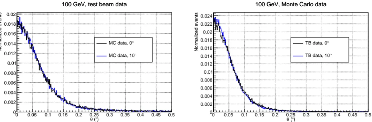
The impact angle of the incident particle on the detector was found to have a negligible effect on the angular resolution. By comparing the resolution plots for 0◦and 10◦ incidence angles no sizeable difference was found; this was confirmed by Monte Carlo simulations (see figure8). 0 0.05 0.1 0.15 0.2 0.25 0.3 0.35 0.4 0.45 0.5 ) ° ( θ 0 0.002 0.004 0.006 0.008 0.01 0.012 0.014 0.016 0.018 0.02 Normalized events
100 GeV, test beam data
°
MC data, 0
°
MC data, 10
100 GeV, test beam data
0 0.05 0.1 0.15 0.2 0.25 0.3 0.35 0.4 0.45 0.5 ) ° ( θ 0 0.002 0.004 0.006 0.008 0.01 0.012 0.014 0.016 0.018 0.02 0.022 0.024 Normalized events
100 GeV, Monte Carlo data
°
TB data, 0
°
TB data, 10
100 GeV, Monte Carlo data
Figure 8. Two-dimensional tracking resolution for 100 GeV electrons for test beam (left) and Monte Carlo (right) data (black: 0◦, blue: 10◦ incidence angle).
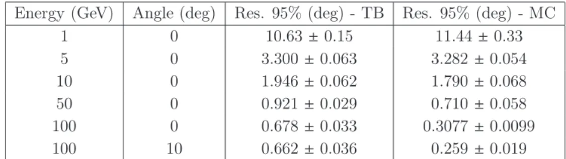
The angular resolution on the XZ projection plane are summarized in tables1 and 2. The agreement between test beam and Monte Carlo data is quite satisfactory, especially at lower energies for 68% containment of the two-dimensional Point Spread Function (PSF). At 95% PSF the agreement gets worse, likely due to residual instrumental effects that result in a not-so-good modeling of the tails of the distribution by the Monte Carlo. Moreover, in the test beam analysis, no particular quality selection criteria were applied in order reduce spurious events or the tails of the angular distribution.
Energy (GeV) Angle (deg) Res. 95% (deg) - TB Res. 95% (deg) - MC 1 0 10.63 ± 0.15 11.44 ± 0.33 5 0 3.300 ± 0.063 3.282 ± 0.054 10 0 1.946 ± 0.062 1.790 ± 0.068 50 0 0.921 ± 0.029 0.710 ± 0.058 100 0 0.678 ± 0.033 0.3077 ± 0.0099 100 10 0.662 ± 0.036 0.259 ± 0.019
Table 2. Two-dimensional angular resolution in the XZ plane of the detector prototype, obtained from test beam (TB) and Monte Carlo (MC) data, for 95% PSF.
7 Conclusions
In this paper, a new instrument design for tracking gamma rays in cosmic-ray space experi-ments has been proposed and characterized. The TIC tracking calorimeter has comparable tracking performance with respect to the current generation of gamma-ray experiments (Fermi, DAMPE) for energies from 1 GeV to ∼ 50 GeV, and better performance above ∼ 50 GeV, while allowing for important design optimizations for multi-particle detection. Data acquired with a detector prototype at CERN test beam facilities showed a good agreement with the Monte Carlo simulation, providing a deep insight on the relevant instrumental effects and a robust validation of the measurement principle.
Acknowledgments
This work was financed by the INFN Commissione Scientifica Nazionale 5. The authors thank F. Cadoux for helping with realizing the detector, and H. Wilkens, L. Gatignon, N. Charitonidis, B. Rae and M. Jeckel for test beam support.
References
[1] W.B. Atwood et al., Design and initial tests of the Tracker-converter of the Gamma-ray Large Area Space Telescope, Astropart. Phys. 28 (2007) pg. 422-434
[2] A. Bulgarelli et al., The AGILE silicon tracker: Pre-launch and in-flight configuration, Nucl. Inst. and Meth. in Phys. A 614 (2010) pg. 213-226
[3] J. D. Sullivan, Geometrical factor and directional response of single and multi-element particle telescopes, Nucl. Inst. and Meth. in Phys. A 95 (1971) pg. 5-11
[4] Y. Asaoka et al., Energy calibration of CALET onboard the International Space Station, Astropart. Phys. 91 (2017) pg. 1-10
[5] J. Chang et al., The DArk Matter Particle Explorer mission, Astropart. Phys. 95 (2017) pg. 6-24
[6] S. Zhang et al., Introduction to the High Energy cosmic-RadiationDetection (HERD) Facility onboard ChinaâĂŹs FutureSpace Station, Proc. of Sc. 301 (2017)
[7] O. Adriani et al., The construction and testing of the silicon position sensitive modules for the LHCf experiment at CERN, JINST 5 (2010) P01012
[8] O. Adriani et al., CaloCube: An isotropic spaceborne calorimeter for high-energy cosmic rays. Optimization of the detector performance for protons and nuclei, Astropart.Phys. 96 (2017) pg. 1-17
[9] O. Adriani et al., The CaloCube project for a space based cosmic ray experiment: design, construction, and first performance of a high granularity calorimeter prototype, JINST 14 (2019) P11004
[10] G. Battistoni et al., Overview of the FLUKA code, Ann. Nucl. En. 82 (2015) 10-18 [11] T.T. Bohlen et al., The FLUKA Code: Developments and Challenges for High Energy and
Medical Applications, Nucl. Data Sh. 120 (2014) 211-214
[12] P. Azzarello et al., The DAMPE silicon-tungsten tracker, Nucl. Inst. and Meth. in Phys. Res. A 831 (2016) 378-384
[13] Fermi collaboration, Fermi LAT performance,
https://www.slac.stanford.edu/exp/glast/groups/canda/lat_Performance.htm [14] G. Barbiellini et al., The AGILE silicon tracker: testbeam results of the prototype silicon
![Figure 2. Angular resolution of TIC for 10 GeV photons as a function of the conversion+selection efficiency, compared to Fermi [13] and DAMPE [5].](https://thumb-eu.123doks.com/thumbv2/123dokorg/4660429.42555/10.892.139.698.164.562/figure-angular-resolution-function-conversion-selection-efficiency-compared.webp)