DIPARTIMENTO
DI
INGEGNERIA
INDUSTRIALE
Dottorato di Ricerca in Ingegneria Meccanica
XI Ciclo N.S. (2009-2012)
“Design and Optimization of a protection device
for laser weld beads of metal alloys for
aerospace applications”
Ing. Gaetano Corrado
Tutor: Coordinatore:
Prof. Vincenzo Sergi Prof. Vincenzo Sergi
TABLE OF CONTENTS
Summary
viiChapter 1
Basic Laser Principles
1.1 Introduction 1
1.2 How the Laser Works 2
1.2.1 Photos and Energy 2
1.2.2 Absorption, Spontaneous and
Stimulated Emissions 4
1.2.3 Population Inversion 7
1.2.4 The Resonator 8
1.2.5 Laser pumping sources 9
1.3 Propagation Characteristics of Laser Beam 10
1.3.1 Beam waist and Divergence 10
1.3.2 Locating the beam waist 12
1.3.3 Higher order Gaussian Laser Beams 16
1.3.4 Transvers Modes and Mode Control 18
1.4.1 Collimation 21 1.4.2 Monochromaticity 21 1.4.3 Coherence 22 1.4.4 Intensity or Irradiance 23 1.4.5 Focusability 24 1.5 Type of Lasers 25
1.5.1 Gas Discharge Laser 26
1.5.2 Semiconductor Diode Lasers 29
1.5.3 Optically Pumped Lasers 31
1.5.4 Diode Pumped a Staid Solid Lasers 33
1.6 Disk Laser 35
1.6.1 The thin Disk Laser principles
(Multipass Pumping) 35
1.6.2 Minimal thermal lensing effect 38
1.6.3 Scaling power regulation 39
Chapter 2
Laser Welding
2.1 Introduction 41
2.2 Process Arrangement 43
2.2.1 Conduction limited welding 44
2.2.2 Deep penetration “keyhole” welding 45
2.2.2 Deep penetration “keyhole” welding 47
2.3 Laser welding parameters 48
2.3.1 Power 49
2.3.3 Wavelength 53
2.3.4 Focal Position 55
2.3.5 Welding Speed 56
2.3.6 Joint Geometries 57
2.3.7 Gas Shroud and Gas Pressure 59
2.3.8 Effect of Gas Pressure — Due to Velocity
and Environment 62
2.3.9 Effect of Material Properties 63
Chapter 3
Automated laser welding apparatus
3.1 Introduction 66
3.2 Problems caused by the oxidation 67
3.3 Solutions proposed in the literature 69
3.4 Proposed Solution 73
3.4.1 Design and realization of the Upper Diffuser 76
3.4.2 Design and realization of the Lower Diffuser 81
3.5 Equipment for experimental works 83
3.5.1 Laser source and focus system 83
3.5.2 Moving system of the laser welding head 86
Chapter 4
Butt laser welding of Titanium alloy
4.1 Introduction 88
4.2 Material: Ti6Al4V Titanium alloy 88
4.3 Configuration of automated laser welding apparatus 91
4.5 Results and discussions: geometrical characteristics,
microstructures and defects 98
4.6 Analysis of the responses 103
4.7 Optimization and Tensile Test 110
Chapter 5
Butt laser welding of Nickel Superalloys
5.1 Introduction 113
5.2 What are Superalloys? 113
5.3 Superalloy Metallurgy 116
5.3.1 Crystal Structures 117
5.3.2 Phases in Superalloys 118
5.4 Haynes 188 119
5.5 Inconel 718 121
5.6 Configuration of automated laser welding apparatus 123
5.7 Design of Experiments 125
5.7.1 Experimental plan arrangement 125
5.7.2 Response variables choice 128
5.8 Results and discussion 130
5.9 Optimization of the responses 134
5.10 Constraint criteria for optimization 137
5.11 Optimal processing condition and tensile test 139
Chapter 6
Edge joint laser welding of Nickel Superalloy6.1 Introduction 143
6.3 Automated laser welding apparatus for edge
joint configuration 147
6.3.1 Edge joint configuration 147
6.3.2 Configuration of automated laser welding
apparatus 148
6.4 Design of experiment 151
6.5 Results and discussions 152
6.5.1 Visual inspections 152 6.5.2 X-ray tests 154 6.6 Macrographic examinations 155 6.7 Micrographic examinations 159
Conclusion
161Reference
164
Summary
In the present thesis an automated laser welding apparatus was designed and developed in order to perform laser , that allows to achieve laser welding in a controlled, versatile, efficient, reliable, simple, and economical way. This system allows to shield not controlled from oxidation and nitriding process, both the melted pool and the material portion just after welding when the oxidation or nitriding critical temperatures, generally between 200 °C and 500 °C are still in place. Oxidation is even more serious when welding titanium, nickel superalloy, zirconium, molybdenum, stainless steel and other gas-reactive metals and alloys. Most of these materials are used for a wide range of applications in aerospace and biomedical fields as well as for piping in petrochemical, food, semiconductor, nuclear, and chemical industries. These metals can be used in contact with corrosive or sensitive materials without contaminating them, thus making them the number one choices for applications requiring long service life and non-contamination.
The resulting oxidized surfaces are not-longer corrosion resistant and further treatment may be necessary. Removing the oxidation using mechanical means, such as grinding, also removes the metal’s passive protective layer.
The automated laser welding apparatus (patent number:
SA2012A000016) was tested with three different joints: butt welding of 3 mm thick Ti6Al4V plates; dissimilar butt welding of 1.5 mm thick of Haynes 188 and Inconel 718 and edge joint of 0.7 mm thick Inconel 625 sheets.
All of the tests were performed with automated laser welding apparatus; the bead quality was discussed in terms of geometrical features, porosity content, microstructure, hardness and strength. This work is divided in three parts.
In the first part, the principles of operation and the different types of laser are discussed, with mention to the advantages of a disk laser source, which is employed in the experimental part. Also, the types of laser welding, the influence of process parameters and the advantages compared to traditional welding techniques are explained.
The second part presents the issue of oxidation caused by welding and the relative solutions proposed in the literature for shielding the bead. Then, the development and the implementation of the automated laser welding apparatus with its components is described.
Finally, the capabilities of the automated laser welding apparatus on three different types of joint are discussed in the last part and the relative results are provided.
Chapter 1
Basic Laser Principles
1.1 Introduction
Lasers are devices that produce intense beams of light which are monochromatic, coherent, and highly collimated. The wavelength (color) of laser light is extremely pure (monochromatic) when compared to other sources of light, and all of the photons (energy) that make up the laser beam have a fixed phase relationship (coherence) with respect to one another. Light from a laser typically has very low divergence. It can travel over great distances or can be focused to a very small spot (area on a surface illuminated by a laser) with a brightness which exceeds that of the sun. Because of these properties, lasers are used in a wide variety of applications in all walks of life. The basic operating principles of the laser were put forth by Charles Townes and Arthur Schalow from the Bell Telephone Laboratories in 1958, and the first actual laser, based on a pink ruby crystal, was demonstrated in 1960 by Theodor Maiman at Hughes Research Laboratories. Since that time, literally thousands of lasers have been invented (including the edible “Jello” laser), but only a much smaller number have found practical applications in scientific, industrial, commercial, and military applications. The helium neon laser (the first continuous-wave laser), the semiconductor diode laser, and air-cooled ion lasers have found broad OEM application.
The term “laser” is an acronym for Light Amplification by Stimulated Emission of Radiation. To understand the laser, one needs to understand the meaning of these terms. The term “light” is generally accepted to be electromagnetic radiation ranging from 1 nm to 1000 μm in wavelength. The visible spectrum (what we see) ranges from approximately 400 to
700 nm. The wavelength range from 700 nm to 10 μm is considered the near infrared (NIR), and anything beyond that is the far infrared (FIR). Conversely, 200 to 400 nm is called ultraviolet (UV); below 200 nm is the deep ultraviolet (DUV).
1.2 How the Laser Works
1.2.1 Photos and Energy
In 1915, Neils Bohr proposed a model of the atom that explained a wide variety of phenomena that were puzzling scientists in the late 19th century. This simple model became the basis for the field of quantum mechanics and, although not fully accurate by today’s understanding, still is useful for demonstrating laser principles.
In Bohr’s model, shown in Figure 1.1, electrons orbit the nucleus of an atom. Unlike earlier “planetary” models, the Bohr atom has a limited number of fixed orbits that are available to the electrons. Under the right circumstances an electron can go from its ground state (lowest-energy orbit) to a higher (excited) state, or it can decay from a higher state to a lower state, but it cannot remain between these states. The allowed energy states are called “quantum” states and are referred to by the principal “quantum numbers” 1, 2, 3, etc. The quantum states are represented by an energy-level diagram.
For an electron to jump- to a higher quantum state, the atom must receive energy from the outside world. This can happen through a variety of mechanisms such as inelastic or semielastic collisions with other atoms and absorption of energy in the form of electromagnetic radiation (e.g., light). Likewise, when an electron drops from a higher state to a lower state, the atom must give off energy, either as kinetic activity nonradiative transitions) or as electromagnetic radiation (radiative transitions). For the remainder of this discussion we will consider only radiative transitions.
In the 1600s and 1700s, early in the modern study of light, there was a great controversy about light’s nature. Some thought that light was made up of particles, while others thought that it was made up of waves. Both concepts explained some of the behavior of light, but not all. It was finally determined that light is made up of particles called “photons” which exhibit both particle-like and wave-like properties. Each photon has an intrinsic energy determined by the equation (1.1)
𝐸 = ℎ ∙ 𝑣 (1.1) where v is the frequency of the light and h is Planck’s constant.
Since, for a wave, the frequency and wavelength are related by the equation
λ𝑣 = 𝑐 (1.2) where λ is the wavelength of the light and c is the speed of light in a vacuum, equation (1.1) can be rewritten as
𝐸 = ℎ𝑐/λ (1.3) It is evident from this equation that the longer the wavelength of the light, the lower the energy of the photon; consequently, ultraviolet light is much more “energetic” than infrared light.
Returning to the Bohr atom: for an atom to absorb light (i.e., for the light energy to cause an electron to move from a lower energy state En to a higher energy state Em), the energy of a single photon must equal, almost exactly, the energy difference between the two states. Too much energy or too little energy and the photon will not be absorbed. Consequently, the wavelength of that photon must be
λ = ℎ𝑐/∆𝐸
where (1.4)
∆𝐸 = 𝐸𝑚− 𝐸𝑛 Likewise, when an electron decays to a lower energy level in a radiative transition, the photon of light given off by the atom must also have an energy equal to the energy difference between the two states.
1.2.2 Absorption, Spontaneous and Stimulated Emissions
In general, when an electron is in an excited energy state, it must eventually decay to a lower level, giving off a photon of radiation. This event is called “spontaneous emission,” and the photon is emitted in a random direction and a random phase. The average time it takes for the electron to decay is called the time constant for spontaneous emission, and is represented by τ.
On the other hand, if an electron is in energy state E2, and its decay path is to E1, but, before it has a chance to spontaneously decay, a photon happens to pass by whose energy is approximately E2-E1, there is a probability that the passing photon will cause the electron to decay in such a manner that a photon is emitted at exactly the same wavelength, in exactly the same direction, and with exactly the same phase as the passing photon. This process is called “stimulated emission.” Absorption, spontaneous emission, and stimulated emission are illustrated in Figure 1.2.
Figure 1.2 Absorption Spontaneous and Stimulated emission
Now consider the group of atoms shown in Figure 1.3: all begin in exactly the same excited state, and most are effectively within the stimulation range of a passing photon. We also will assume that t is very long, and that the probability for stimulated emission is 100 percent. The incoming (stimulating) photon interacts with the first atom, causing stimulated emission of a coherent photon; these two photons then interact with the next two atoms in line, and the result is four coherent photons, on down the line. At the end of the process, we will have eleven coherent photons, all with identical phases and all traveling in the same direction. In other words, the initial photon has been “amplified” by a factor of eleven. Note that the energy to put these atoms in excited states is
provided externally by some energy source which is usually referred to as the “pump” source.
Figure 1.3 Amplification by stimulated emission
Of course, in any real population of atoms, the probability for stimulated emission is quite small. Furthermore, not all of the atoms are usually in an excited state; in fact, the opposite is true. Boltzmann’s principle, a fundamental law of thermodynamics, states that, when a collection of atoms is at thermal equilibrium, the relative population of any two energy levels is given by
𝑁1
𝑁2 = exp �−
𝐸2− 𝐸1
𝑘 ∙ 𝑇 � (1.5) where N2 and N1 are the populations of the upper and lower energy states, respectively, T is the equilibrium temperature, and k is Boltzmann’s constant. Substituting hn for E2-E1 yields
∆𝑁 = 𝑁2− 𝑁1 = �1 − 𝑒−ℎ𝑣𝑘𝑇� 𝑁1 (1.6) For a normal population of atoms, there will always be more atoms in the lower energy levels than in the upper ones. Since the probability for an individual atom to absorb a photon is the same as the probability for an excited atom to emit a photon via stimulated emission, the collection of real atoms will be a net absorber, not a net emitter, and amplification will not be possible. Consequently, to make a laser, we have to create a “population inversion.”
1.2.3 Population Inversion
Atomic energy states are much more complex than indicated by the description above. There are many more energy levels, and each one has its own time constants for decay. The four-level energy diagram shown in Figure 1.4 is representative of some real lasers.
The electron is pumped (excited) into an upper level E4 by some mechanism (for example, a collision with another atom or absorption of high-energy radiation). It then decays to E3, then to E2, and finally to the ground state E1. Let us assume that the time it takes to decay from E2 to E1 is much longer than the time it takes to decay from E2 to E1. In a large population of such atoms, at equilibrium and with a continuous pumping process, a population inversion will occur between the E3 and E2 energy states, and a photon entering the population will be amplified coherently.
1.2.4 The Resonator
Although with a population inversion we have the ability to amplify a signal via stimulated emission, the overall single-pass gain is quite small, and most of the excited atoms in the population emit spontaneously and do not contribute to the overall output. To turn this system into a laser, we need a positive feedback mechanism that will cause the majority of the atoms in the population to contribute to the coherent output. This is the resonator, a system of mirrors that reflects undesirable (off-axis) photons out of the system and reflects the desirable (on-axis) photons back into the excited population where they can continue to be amplified.
Now consider the laser system shown in Figure 1.5.
Figure 1.5 Schematic diagram of a basic laser
The lasing medium or gain medium is pumped continuously to create a population inversion at the lasing wavelength. As the excited atoms start
to decay, they emit photons spontaneously in all directions. Some of the photons travel along the axis of the lasing medium, but most of the photons are directed out the sides. The photons traveling along the axis have an opportunity to stimulate atoms they encounter to emit photons, but the ones radiating out the sides do not. Furthermore, the photons traveling parallel to the axis will be reflected back into the lasing medium and given the opportunity to stimulate more excited atoms. As the on-axis photons are reflected back and forth interacting with more and more atoms, spontaneous emission decreases, stimulated emission along the axis predominates, and we have a laser.
Finally, to get the light out of the system, one of the mirrors is has a partially transmitting coating that couples out a small percentage of the circulating photons. The amount of coupling depends on the characteristics of the laser system and varies from a fraction of a percent for helium neon lasers to 50 percent or more for high-power lasers.
1.2.5 Laser pumping sources
Laser pumping sources are the means by which energy is transferred into the laser gain medium to produce the required population inversion ΔN21. These pumping sources generally consist of either electrons flowing within the medium or light being absorbed by the medium.
Electron pumping - Electron pumping is used primarily in gaseous or semiconductor gain media. In gases, many electrons are produced when a few initial electrons within the gain medium are accelerated by an electric field within the medium and these many electrons then collide with neutral atoms, exciting those atoms to higher-lying energy levels and even ionizing some of the atoms (removing an electron). The freed electrons are also accelerated, producing an avalanche of electrons and therefore an electrical current within the medium. The electrons lose their energy by transferring it to the atoms during the collision process. Some of the lasers operate on a pulsed basis, applying a large amount of current for a short
period of time. Others operate on a continuous (cw) basis, using a much smaller but continuous current.
Optical pumping - Optical pumping of lasers generally applies to the pumping of liquid (dye) lasers and to dielectric solid-state lasers and is provided by either flash-lamps or other lasers. The most common types of flash-lamps used for pumping lasers are narrow, cylindrical quartz tubes with metal electrodes mounted on the ends, filled with a gaseous species such as xenon that serves as the radiating material within the lamp. A voltage is applied across the electrodes of the flash-lamp and current flows through the gas, populating excited levels of the atoms within the gas that radiate and produce intense light emission. The process is similar to that of electron excitation of lasers described above except that a population inversion is not produced and the radiating material of the lamp radiates via spontaneous emission, rather than by stimulated emission as in the case of a laser gain medium. The pumping wavelength of the flash-lamp is determined by the gaseous medium inserted within the flash-lamp tube. Xenon is the most common species because of both its radiating efficiency and its emission of a broad spectrum of wavelengths from which to choose in matching the lamp emission to the pumping absorption bands of the laser.
1.3 Propagation Characteristics of Laser Beam
1.3.1 Beam waist and Divergence
Diffraction causes light waves to spread transversely as they propagate, and it is therefore impossible to have a perfectly collimated beam. The spreading of a laser beam is in accord with the predictions of diffraction theory. Under ordinary circumstances, the beam spreading can be so small it can go unnoticed. The following formulas accurately describe beam spreading, making it easy to see the capabilities and limitations of laser beams.
Even if a Gaussian TEM00 laser-beam wave-front were made perfectly flat at some plane, with all rays there moving in precisely parallel directions, it would acquire curvature and begin spreading in accordance with 𝑅(𝑧) = 𝑧 �1 + �𝜋 ∙ 𝑤0𝜆 ∙ 𝑧 �2 2 � (1.7) and 𝑤(𝑧) = 𝑤0�1 + �𝜋 ∙ 𝑤𝜆 ∙ 𝑧 02� 2 � 1 2 (1.8) where z is the distance propagated from the plane where the wave-front is flat, l is the wavelength of light, w0 is the radius of the 1/e2 irradiance
contour at the plane where the wave-front is flat, w(z) is the radius of the 1/e2 contour after the wave has propagated a distance z, and R(z) is the wave-front radius of curvature after propagating a distance z. R(z) is infinite at z=0, passes through a minimum at some finite z, and rises again toward infinity as z is further increased, asymptotically approaching the value of z itself.
The plane z=0 marks the location of a beam waist, or a place where the wave-front is flat, and w0 is called the beam waist radius.
The irradiance distribution of the Gaussian TEM00 beam, namely,
𝐼(𝑟) = 𝐼0𝑒−2𝑟2/𝑤2
= 𝜋𝑤2𝑃2𝑒−2𝑟
2
𝑤2 (1.9)
where w=w(z) and P is the total power in the beam, is the same at all cross sections of the beam. The invariance of the form of the distribution is a special consequence of the presumed Gaussian distribution at z=0. Simultaneously, as R(z) asymptotically approaches z for large z, w(z) asymptotically approaches the value
𝑤(𝑧) =𝜋 ∙ 𝑤𝜆 ∙ 𝑧
0 (1.10) where z is presumed to be much larger than πw02/ λ so that the 1/e2
irradiance contours asymptotically approach a cone of angular radius.
𝜃 =𝑤(𝑧)𝑧 =𝜋 ∙ 𝑤𝜆
0 (1.11) This value is the far-field angular radius (half-angle divergence) of the Gaussian TEM00 beam. The vertex of the cone lies at the center of the waist (see Figure 1.6).
It is important to note that, for a given value of λ, variations of beam diameter and divergence with distance z are functions of a single parameter, w0, the beam waist radius.
Figure 1.6 Growth in beam diameter as a function of distance from beam
waist
1.3.2 Locating the beam waist
Unlike conventional light beams, Gaussian beams do not diverge linearly, as can be seen in Figure 1.6. Near the laser, the divergence angle is extremely small; far from the laser, the divergence angle approaches the asymptotic limit described in equation (1.11) above. The Raleigh range
(zR), defined as the distance over which the beam radius spreads by a factor of √2 is given by
𝑧𝑅 = 𝜋 ∙ 𝑤0 2
𝜆 (1 .12) The Raleigh range is the dividing line between near-field divergence and mid-range divergence. Far-field divergence (the number quoted in laser specifications) must be measured at a point >zR (usually 10zR will suffice). This is a very important distinction because calculations for spot size and other parameters in an optical train will be inaccurate if near- or mid-field divergence values are used. For a tightly focused beam, the distance from the waist (the focal point) to the far field can be a few millimeters or less. For beams coming directly from the laser, the far-field distance can be measured in meters.
For a Gaussian laser beam, the location (and radius) of the beam waist is determined uniquely by the radius of curvature and optical spacing of the laser cavity mirrors because, at the reflecting surfaces of the cavity mirrors, the radius of curvature of the propagating beam is exactly the same as that of the mirrors. Consequently, for the flat/curved cavity shown in Figure 1.7 (a), the beam waist is located at the surface of the flat mirror. For a symmetric cavity (b), the beam waist is halfway between the mirrors; for non-symmetric cavities (c and d), the beam waist is located by using the equation
𝑧1 =𝑅𝐿(𝑅2− 𝐿)
1+ 𝑅2− 2𝐿 (1.13) and
𝑧1+ 𝑧2 = 𝐿 (1.14) where L is the effective mirror spacing, R1 and R2 are the radii of
beam waist of mirrors 1 and 2, respectively. (Note that distances are measured from the beam waist, and that, by convention, mirror curvatures that are concave when viewed from the waist are considered positive, while those that are convex are considered negative.)
In any case but that of a flat output mirror, the beam waist is refracted as it passes through the mirror substrate. If the output coupler’s second surface is flat, the effective waist of the refracted beam is moved toward the output coupler and is reduced in diameter. However, by applying a spherical correction to the second surface of the output coupler, the location of the beam waist can be moved to the output coupler itself, increasing the beam waist diameter and reducing far-field divergence. (See Calculating a Correcting Surface.)
It is useful, particularly when designing laser cavities, to understand the effect that mirror spacing has on the beam radius, both at the waist and at the curved mirror. Figure 1.8 plots equations (1.7) and (1.8) as a function of R/z (curved mirror radius divided by the mirror spacing). As the mirror spacing approaches the radius of curvature of the mirror (R/z=1), the beam waist decreases dramatically, and the beam radius at the curved mirror becomes very large. On the other hand, as R/z becomes large, the beam radius at the waist and at the curved mirror are approximately the same.
Figure 1.8 Beam waist and output diameter as a function of mirror radius and
1.3.3 Higher order Gaussian Laser Beams
In the real world, the truly 100-percent, single transverse mode, Gaussian laser beam (also called a pure or fundamental mode beam) described by equations (1.7) and (1.8) is very hard to find. Low-power beams from helium neon lasers can be a close approximation, but the higher the power of the laser, and the more complex the excitation mechanism (e.g., transverse discharges, flash-lamp pumping), or the higher the order of the mode, the more the beam deviates from the ideal.
To address the issue of higher order Gaussian beams and mixed mode beams, a beam quality factor, M2, has come into general use. A mixed mode is one where several modes are oscillating in the resonator at the same time. A common example is the mixture of the lowest order single transverse mode with the doughnut mode, before the intracavity mode limiting aperture is critically set to select just the fundamental mode. Because all beams have some wave-front defects, which implies they contain at least a small admixture of some higher order modes, a mixed mode beam is also called a “real” laser beam.
For a theoretical single transverse mode Gaussian beam, the value of the waist radius–divergence product is (from equation (1.11)):
𝑤0 𝜃 = 𝜆/𝜋 (1.15) It is important to note that this product is an invariant for transmission of a beam through any normal, high-quality optical system (one that does not add aberrations to the beam wavefront). That is, if a lens focuses the single mode beam to a smaller waist radius, the convergence angle coming into the focus (and the divergence angle emerging from it) will be larger than that of the unfocused beam in the same ratio that the focal spot diameter is smaller: the product is invariant.
For a real laser beam, we have
where W0 and Ɵ are the 1/e2 intensity waist radius and the far-field
half-divergence angle of the real laser beam, respectively. Here we have introduced the convention that upper case symbols are used for the mixed mode and lower case symbols for the fundamental mode beam coming from the same resonator. The mixed-mode beam radius W is M times larger than the fundamental mode radius at all propagation distances. Thus the waist radius is that much larger, contributing the first factor of M in equation (1.16). The second factor of M comes from the half-angle divergence, which is also M times larger. The waist radius–divergence half-angle product for the mixed mode beam also is an invariant, but is M2 larger. The fundamental mode beam has the smallest divergence allowed by diffraction for a beam of that waist radius. The factor M2 is called the “times-diffraction-limit” number or (inverse) beam quality; a diffraction-limited beam has an M2 of unity.
For a typical helium neon laser operating in TEM00 mode, M2 < 1.05.
Ion lasers typically have an M2 factor ranging from 1.1 to 1.7. For high-energy multimode lasers, the M2 factor can be as high as 30 or 40. The M2 factor describes the propagation characteristics (spreading rate) of the laser beam. It cannot be neglected in the design of an optical train to be used with the beam. Truncation (aperturing) by an optic, in general, increases the M2 factor of the beam.
The propagation equations (analogous to equations (1.7) and (1.8) for the mixed-mode beam W(z) and R(z) are as follows:
𝑊(𝑧) = 𝑊0�1 + �𝑧𝑀 2𝜆 𝜋𝑊02� 2 � 1/2 = 𝑊0�1 + �𝑍𝑅𝑧� 2 � (1.17) and 𝑅(𝑧) = 𝑧 �1 + �𝑧𝑀𝜋𝑊202𝜆� 2 � = 𝑊0�1 + �𝑍𝑅𝑧 � 2 � (1.18) The Rayleigh range remains the same for a mixed mode laser beam
𝑍𝑅 = 𝜋𝑊𝑀20𝜆 =2 𝜋𝑤𝜆 (1.19)02 Now consider the consequences in coupling a high M2 beam into a fiber. Fiber coupling is a task controlled by the product of the focal diameter (2Wf) and the focal convergence angle (θf). In the tight focusing limit, the
focal diameter is proportional to the focal length f of the lens, and is inversely proportional to the diameter of the beam at the lens (i.e., 2Wf ∝
f/Dlens).
The lens-to-focus distance is f, and, since f×θf is the beam diameter at
distance f in the far field of the focus, Dlens∝ f×θf. Combining these
proportionalities yields
𝑊𝑓𝜃𝑓 = 𝑐𝑜𝑠𝑡𝑎𝑛𝑡
for the fiber-coupling problem as stated above. The diameter-divergence product for the mixed-mode beam is M2 larger than the fundamental mode beam in accordance with equations (1.15) and (1.16).
There is a threefold penalty associated with coupling a beam with a high M2 into a fiber:
1) the focal length of the focusing lens must be a factor of 1/M2 shorter than that used with a fundamental-mode beam to obtain the same focal diameter at the fiber;
2) the numerical aperture (NA) of the focused beam will be higher than that of the fundamental beam (again by a factor of 1/M2) and may exceed the NA of the fiber;
3) the depth of focus will be smaller by 1/M2 requiring a higher degree of precision and stability in the optical alignment.
1.3.4 Transvers Modes and Mode Control
The fundamental TEM00 mode is only one of many transverse modes
cavity. Figure 1.9 shows examples of the primary lower-order Hermite-Gaussian (rectangular) modes.
Note that the subscripts m and n in the mode designation TEMmn are
correlated to the number of nodes in the x and y directions. The propagation equation can also be written in cylindrical form in terms of radius (ρ) and angle (ϕ). The eigenmodes (Eρϕ ) for this equation are a series of axially symmetric modes, which, for stable resonators, are closely approximated by Laguerre-Gaussian functions, denoted by TEMρϕ. For the lowest-order mode, TEM00, the Hermite-Gaussian and
Laguerre-Gaussian functions are identical, but for higher-order modes, they differ significantly, as shown in Figure 1.10.
The mode, TEM01*, also known as the “bagel” or “doughnut” mode, is
considered to be a superposition of the Hermite-Gaussian TEM10 and
TEM01 modes, locked in phase and space quadrature.
In real-world lasers, the Hermite-Gaussian modes predominate since strain, slight misalignment, or contamination on the optics tends to drive the system toward rectangular coordinates. Nonetheless, the Laguerre-Gaussian TEM10 “target” or “bulls-eye” mode is clearly observed in
well-aligned gas-ion and helium neon lasers with the appropriate limiting apertures.
Figure 1.10 Low-order axisymmetric resonator modes
The transverse modes for a given stable resonator have different beam diameters and divergences. The lower the order of the mode is, the smaller the beam diameter, the narrower the far-field divergence, and the lower the M2 value. For example, the TEM01* doughnut mode is
approximately 1.5 times the diameter of the fundamental TEM00 mode,
and the Laguerre TEM10 target mode is twice the diameter of the TEM00
mode. The theoretical M2 values for the TEM00, TEM01*, and TEM10
modes are 1.0, 2.3, and 3.6, respectively. Because of its smooth intensity profile, low divergence, and ability to be focused to a diffraction-limited spot, it is usually desirable to operate in the lowest-order mode possible, TEM00. Lasers, however, tend to operate at the highest-order mode
possible, either in addition to, or instead of, TEM00 because the larger
beam diameter may allow them to extract more energy from the lasing medium.
The primary method for reducing the order of the lasing mode is to add sufficient loss to the higher-order modes so that they cannot oscillate without significantly increasing the losses at the desired lower-order mode. In most lasers this is accomplished by placing a fixed or variable aperture inside the laser cavity. Because of the significant differences in beam diameter, the aperture can cause significant diffraction losses for the higher-order modes without impacting the lower-order modes. As an example, consider the case of a typical argon-ion laser with a long-radius cavity and a variable mode-selecting aperture.
When the aperture is fully open, the laser oscillates in the axially symmetric TEM10 target mode. As the aperture is slowly reduced, the
output changes smoothly to the TEM01* doughnut mode, and finally to the
TEM00 fundamental mode. In many lasers, the limiting aperture is
provided by the geometry of the laser itself. For example, by designing the cavity of a helium neon laser so that the diameter of the fundamental mode at the end of the laser bore is approximately 60 percent of the bore diameter, the laser will naturally operate in the TEM00 mode.
1.4 Laser properties related to applications
1.4.1 Collimation
Collimated light is light in which all of the light rays or waves are traveling in a specific direction and hence they are all parallel to each other. Lasers produce the most collimated light of any type of light source. Such collimated light is used for reference beams in construction, leveling and grading land, alignment of pipe such as sewer pipe, and sending light over long distances without suffering significant divergence, and in laser pointers. Producing the most collimated light, in other words the least divergent light, is determined by the cavity mirror properties including the radii of curvature of the mirrors and the separation between mirrors as indicated in equations (1.7), (1.8), and (1.11). For the smallest beam divergence, w0 must be large, as you can see from equation (1.11).
Also, the rays of the laser beam are the most parallel when the beam is at the location of the minimum beam waist w0 as described in equations
(1.8), (1.18), and (1.19).
1.4.2 Monochromaticity
Monochromaticity refers to how pure in color (frequency or wavelength) the laser beam is or, in other words, how narrow the laser
beam frequency bandwidth is. If the laser is operating in a single longitudinal mode actual laser linewidth can be significantly narrower, the width of a single longitudinal mode beam. For most applications requiring a single narrow wavelength, most lasers would normally provide a sufficiently narrow frequency output bandwidth, of the order of 109–1011 Hz. This would represent a bandwidth that is less than 0.1% of the frequency or wavelength of the beam itself (or even smaller in most instances). However, in some applications, such as in remote sensing or in establishing a new frequency standard, a much narrower linewidth is required. Linewidths of the order of 1 MHz (106 Hz) or less can be obtained by operating with a single longitudinal and single transverse mode (TEM00). The narrowing is enhanced by choosing highly reflecting
mirrors, constructing a very stable mirror cavity in conjunction with the amplifier by eliminating vibrations of the mirrors and other cavity elements, and providing temperature stability.
1.4.3 Coherence
Coherence refers to the how much in step or in phase various portions of a single laser beam are. The closeness in phase of various portions of the laser frequency bandwidth is referred to as temporal or longitudinal coherence. The closeness in phase of different spatial portions of the beam after the beam has propagated a certain distance is referred to as spatial or transverse coherence. This phased relationship determines how readily the various portions of the beam can interfere with each other, after the beam has propagated a specific distance, to produce such effects as diffraction (bending) of light and related applications such as holography. Typically, applications involve dividing the beam into two or more beams that travel different lengths or pathways and are then recombined. When they are recombined they will interfere with each other, producing the desired effect if those parts are still in phase (coherent); if they are no longer in phase, the effect will not occur. The coherence length is used to describe the beam propagation distance over
which the beams stay in phase. For longitudinal or temporal coherence, the coherence length lC is related to the wavelength λ and the total
frequency bandwidth of the laser ΔνL by
𝑙𝐶 = ∆𝜆 (1.20)𝜆2 Δλ is the actual bandwidth of the laser beam given in wavelength units.
For transverse or spatial coherence, the transverse coherence length lt is
related to the laser wavelength λ, the laser source diameter at its origin s, and the distance r the beam has propagated from its origin, by the following relationship.
𝑙𝑟 = 𝑟𝜆𝑠 (1.21)
1.4.4 Intensity or Irradiance
Intensity or irradiance is the power of the laser beam divided by the cross-sectional area of the beam. It is thus typically given in watts per square centimeter (W/cm2). It is a measure of the amount of energy that can be applied to a specific region within a given amount of time. It is one of the two most important parameters in using the laser for materials processing applications such as welding, cutting, heat treating, ablating, and drilling, or for laser surgery. The other important parameter is the laser wavelength, since the amount of absorption of all materials, including biological materials, is dependent upon the wavelength of the light. In some instances a deep penetration of the beam is desired, for example in doing processes that must be carried out quickly. In that situation, a laser wavelength in which the material has a relatively low absorption would be selected. Other applications might require a shallow penetration in order to control the quality of the edge to be left after the process is completed, such as in some surgical processes or in drilling
very small holes. Thus, a wavelength region of high absorption would be chosen for the laser. A general rule is that absorption is very high for most materials at ultraviolet wavelengths and decreasing at longer wavelengths. However, this does not hold true for all materials or for all wavelengths. Many materials have high absorption peaks at specific wavelengths that could occur anywhere in the spectrum, so one must be careful to obtain the absorption versus wavelength curves for the desired material before choosing the specific laser.
Radiance is a parameter that includes the beam intensity (W/cm2) and takes into account the beam divergence angle. The divergence angle is generally given in steradians, which is a three-dimensional angular measurement as opposed to the term degrees, which describes angular spread in only two dimensions (in a plane). A complete sphere contains 4π steradians. Hence, radiance is given in units of watts per unit area per unit solid angle or (W/cm2-sr). Laser beam divergence is usually given in milliradians (mr) because of the very low divergence of most lasers. The approximate beam divergence in radians can be obtained by measuring the laser beam diameter at a specific, relatively long distance from the laser and dividing it by the square of the distance to where the measurement is made.
Radiance becomes useful when a beam must be propagated over a reasonable distance before it is used or where the divergence can affect the focusing ability of the beam. Since most materials applications do not involve the tightest focusing possible for a given beam, intensity is usually the more important parameter.
1.4.5 Focusability
Many applications of lasers involve their ability to be focused to a very small spot size. Perhaps one of the most demanding applications is in focusing the small diode laser in a compact disk player. To store as much information as possible on each disk, that information must be included in the smallest grooves possible on the disk. The width of the grooves is
determined by the ability of a laser beam to access a single groove without overlapping into adjacent grooves. Hence, the diameter of the spot size to which the laser beam can be focused becomes a very important parameter.
The smallest diameter that can be obtained with a focused laser, assuming that a single TEM00 mode can be obtained from the laser, is
approximately the dimension of the wavelength of the laser and is given by the following expression
𝑑𝑚𝑖𝑛≅ 4𝜆 � 𝑓𝑑
𝑙�
𝜋 (1.22) in which the f/dl is the focal length of the lens used for the focusing
divided by the useful diameter of the lens, the same notation as on camera lenses. If the laser beam is less than the actual lens diameter, the beam diameter is used instead of the lens diameter in determining the f/dl. In
other words, a laser operating in the visible spectral region with a wavelength of the order of 500 nm could be focused to a size of less than one hundredth the width of a human hair! The effective f/dl focusing lens
(ratio of focal length to laser beam diameter intercepted by the lens) must be of the order of unity to obtain such a small focus. Most lasers, however, can be focused relatively easily to spot diameters of the order of 0.1–0.2 mm. Extra care must be taken in terms of beam quality (mode quality) and lens focal length to obtain smaller spot diameters.
1.5 Type of Lasers
Since the discovery of the laser, literally thousands of types of lasers have been discovered. However, only a relative few of these lasers have found broadly based, practical applications.
Lasers can be broadly classified into four categories: gas discharge lasers, semiconductor diode lasers, optically pumped lasers, and “other,” a category which includes chemical lasers, gas-dynamics lasers, x-ray
lasers, combustion lasers, and others developed primarily for military applications. These lasers are not discussed further here.
1.5.1 Gas Discharge Laser
In principle, gas-discharge lasers are inherently simple—fill a container with gas, put some mirrors around it, and strike a discharge. In practice, they are much more complex because the gas mix, discharge parameters, and container configuration must be specifically and carefully designed to create the proper conditions for a population inversion. Furthermore, careful consideration must be given to how the discharge will react with its container and with the laser optics. Finally, since the temperature of the gas can affect the discharge conditions, questions of cooling must be addressed.
Figure 1.11 below shows a cutaway of a helium neon laser, one of the simplest gas-discharge lasers. An electrical discharge is struck between the anode and cathode.
The most common types of gas-discharge lasers are helium neon lasers, helium cadmium lasers (a metal-vapor laser), noble-gas ion lasers (argon, krypton), carbon-dioxide lasers, and the excimer-laser family. Each of these will be discussed briefly below.
• Helium Neon Lasers
The helium-neon laser (HeNe) was the first gas laser. The most widely used laser wavelength is the red wavelength (632.8 nm) with a cw power output ranging from 1 to 100 mW and laser lengths varying from 10 to 100 cm. HeNe lasers can also be operated at the 543.5 nm green wavelength and several infrared wavelengths. Initiation of a relatively low electrical current through a low-pressure gas discharge tube containing a mixture of helium and neon gases produces the population inversion. With this gas mixture, helium metastable atoms are first excited by electron collisions with helium ground-state atoms. This energy is then transferred to the desired neon excited energy levels, thereby producing the required population inversion with lower-lying helium energy levels.
• Helium Caldium Lasers
Helium cadmium (HeCd) lasers are, in many respects, similar to the HeNe laser with the exception that cadmium metal, the lasing medium, is solid at room temperature. The HeCd laser is a relatively economical, cw source for violet (442 nm) and ultraviolet (325 nm) output. Because of its excellent wavelength match to photopolymer and film sensitivity ranges, it is used extensively for three-dimensional stereolithography and holographic applications.
As mentioned above, cadmium, a metal, is solid at room temperature. For lasing to occur, the metal must be evaporated from a reservoir, and then the vapor must be distributed uniformly down the laser bore. This is accomplished through a process called electrophoresis. Because cadmium will plate out on a cool surface, extreme care must be taken in the design of the laser to contain the cadmium and to protect the optics and windows from contamination, since even a slight film will introduce sufficient
losses to stop lasing. The end of life usually occurs when cadmium is depleted from its reservoir.
• Noble-Gas ion Lasers
The argon ion laser and the krypton ion laser provide a wide range of visible and ultraviolet laser wavelengths. They produce cw output at wavelengths ranging from 275 to 686 nm and powers of up to tens of watts. Running a dc current through a long, narrow-bore plasma discharge tube filled with a low-pressure (0.1 torr) argon or krypton gas produces the population inversion. The argon atoms must be ionized to the first through third ionization stages to reach the appropriate energy levels for laser action. As a result, these lasers are relatively inefficient but still extremely useful for certain applications because of their short wavelengths.
• Carbon Dioxide Lasers
Because of their ability to produce very high power with relative efficiency, carbon dioxide (CO2) lasers are used primarily for materials-processing applications. The standard output of these lasers is at 10.6 μm, and output power can range from less than 1W to more than 10 kW.
Unlike atomic lasers, CO2 lasers work with molecular transitions (vibrational and rotational states) which lie at low enough energy levels that they can be populated thermally, and an increase in the gas temperature, caused by the discharge, will cause a decrease in the inversion level, reducing output power. To counter this effect, high-power cw CO2 lasers use flowing gas technology to remove hot gas from the discharge region and replace it with cooled (or cooler) gas. With pulsed CO2 lasers that use transverse excitation, the problem is even more severe, because, until the heated gas between the electrodes is cooled, a new discharge pulse cannot form properly.
A variety of types of CO2 lasers are available. High-power pulsed and cw lasers typically use a transverse gas flow with fans which move the gas through a laminar-flow discharge region, into a cooling region, and
back again. Low-power lasers most often use waveguide structures, coupled with radio-frequency excitation, to produce small, compact systems.
• Noble-Gas ion Lasers
The term excimer or “excited dimer” refers to a molecular complex of two atoms which is stable (bound) only in an electronically excited state. These lasers, which are available only as pulsed lasers, produce intense output in the ultraviolet and deep ultraviolet. The lasers in this family are XeFl (351 nm), XeCl (308 nm), KrF (248 nm), KrCl (222 nm), ArF (193 nm), and F2 (157 nm). They are used extensively in photolithography, micromachining, and medical (refractive eye surgery) applications.
At first glance, the construction of an excimer laser is very similar to that of a transverse-flow, pulsed CO2 laser. However, the major difference is that the gases in the system are extremely corrosive and great care must be taken in the selection and passivation of materials to minimize their corrosive effects. A system built for CO2 would fail in minutes, if not seconds.
The principal advantage of an excimer laser is its very short wavelength. The excimer output beam can be focused to a spot diameter that is approximately 40 times smaller than the CO2 laser beam with the same beam quality. Furthermore, whereas the long CO2wavelength removes material thermally via evaporation (boiling off material), the excimer lasers with wavelengths near 200 nm remove material via ablation (breaking molecules apart), without any thermal damage to the surrounding material.
1.5.2 Semiconductor Diode Lasers
The means of generating optical gain in a diode laser, the recombination of injected holes and electrons (and consequent emission of photons) in a forward-biased semiconductor pn junction, represents the direct conversion of electricity to light. This is a very efficient process, and
practical diode laser devices reach a 50-percent electrical-to-optical power conversion rate, at least an order of magnitude larger than most other lasers.
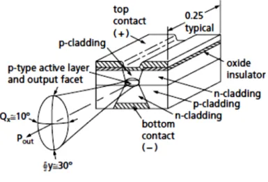
In addition to a means to create optical gain, a laser requires a feedback mechanism, a pair of mirrors to repeatedly circulate the light through the gain medium to build up the resulting beam by stimulated emission. The stripe structures needed to make a laser diode chip are formed on a single crystal wafer using the standard photolithographic patterning techniques of the semiconductor industry. The substrate crystal axes are first oriented relative to the patterning such that, after fabrication, a natural cleavage plane is normal to the stripe direction, and cleaving both ends of the chip provides a pair of plane, aligned crystal surfaces that act as a Fabry-Perot resonator for optical feedback. These mirrors use either the Fresnel reflectivity of the facet (often sufficient because of the high gain of diode lasers), or they can be dielectric coated to other reflectivities. This might be desired, for instance, to protect against damage from the high irradiance at the facets. This geometry gives the familiar edge-emitting diode laser (see Figure 1.12).
The semiconductor crystal must be defect free to avoid scattering of carriers and of light. To grow crystal layers without defects, commercial semiconductor lasers use III-V compounds, elements taken from those columns of the periodic table. These form varying alloys with the addition of dopants that can be lattice-matched to each other and to the initial crystal substrate. The band gap of the semiconductor chosen determines the lasing wavelength region. There are three main families: GaN-based lasers with UV-blue outputs, GaAs-based lasers with red-near infrared outputs, and InP-based lasers with infrared outputs. These base crystals are precisely doped with Ga, Al, In, As, and P to precisely control the band gap and index of refraction of the layers in the diode structure.
These compounds are direct band-gap semiconductors with efficient recombination of injected holes and electrons because no phonons (lattice vibrations) are required to conserve momentum in the recombination interaction. The injection layers surrounding the junction, the cladding layers, can be indirect band-gap semiconductors (where phonons are involved).
To make a planar waveguide that concentrates the light in the junction region (confinement between the top and bottom horizontal planes of the active region in Figure 1.12), the cladding layers are made of an alloy of lower refractive index (larger band gap) than the active junction region. This is then termed a double-heterostructure (DH) laser. The output power of the laser is horizontally polarized because the reflectivity of the planar waveguide is higher for the polarization direction parallel to the junction plane. Because the junction region is thin for efficient recombination (typically 0.1 μm), some light spreads into the cladding layers which are therefore made relatively thick (typically 1 μm) for adequate light confinement.
1.5.3 Optically Pumped Lasers
Optically pumped lasers use photons of light to directly pump the lasing medium to the upper energy levels. The very first laser, based on a
synthetic ruby crystal, was optically pumped. Optically pumped lasers can be separated into two broad categories: lamp-pumped and laser pumped. In a lamp-pumped laser, the lasing medium, usually a solid-state crystal, is placed near a high-intensity lamp and the two are surrounded by an elliptical reflector that focuses the light from the lamp into the crystal, as shown in Figure 1.13. In laser-pumped systems, the light from another laser is focused into a crystal (or a stream of dye), as shown in Figure 1.14.
Figure 1.13 Schematic of a lamp-pumped laser
In general, ignoring the efficiency of the pump laser itself, laser pumping is a much more efficient mechanism than lamp pumping because the wavelength of the pump laser can be closely matched to specific absorption bands of the lasing medium, whereas most of the light from a broad-spectrum lamp is not usefully absorbed in the gain medium and merely results in heat that must be removed from the system. Furthermore, the size of the laser pump beam can be tightly controlled, serving as a gain aperture for improving the output mode characteristics of the pumped laser medium. On the other hand, laser pumping is often not suitable for high-energy applications where large laser crystals are required.
Diode-pumped solid-state (DPSS) lasers, a class of laser-pumped lasers, will be discussed in detail below.
1.5.4 Diode Pumped a Staid Solid Lasers
• The DPSS Laser revolution
The optical difficulties encountered with diode lasers—difficulty in coupling to the high divergence light, poor mode quality in the slow axis of wide-stripe lasers, low output power from single-transverse-mode lasers— led to a new philosophy about how best to use these efficient, long-lived, compactlight sources.
The logic is simple. The primary light source (the diode laser) pumps another laser (an infrared crystal laser) to convert to a good mode, the beam of which is wavelength converted (by nonlinear optics techniques) to a visible output. The diode laser source replaces the discharge lamp for optically pumping the gain crystal in a traditional, high-efficiency, infrared laser. The infrared beam is generated in that independent resonator with a good mode, and consequently it can be efficiently converted with an intracavity nonlinear crystal to a visible beam with a good mode. Though power is lost at each step, the result is still a single-mode visible beam generated with a total electrical-to-optical conversion
efficiency of several percent. These DPSS lasers are replacing the older visible gas lasers whose conversion efficiencies rarely reach 0.1 percent.
• End- and side-pumping geometries
The first DPSS lasers were made by focusing the diode light from a single laser diode emitter through the high-reflector coating (at 1.06 μm) on the end of the Nd:YAG rod. This “end-pumping” geometry provide good overlap between the pumped volume and the lasing volume, but it limited the pump power to that available from single-mode diode emitters.
In order to increase laser output and reduce cost (diode lasers suitable for end pumping are twice as expensive as diode laser arrays), diode arrays were mounted along the length of the laser rod.However, because of poor overlap of the pump beam with the 1.06 μm beam, the efficiency of this “side-pumping” technique was only half that of end-pumping geometries. No pump diode cost savings resulted.
Then in the late 1980s two advances were made. First, a variety of new laser rod materials, better tailored to take advantage of diode laser pumps, were introduced. Nd:YVO4 crystals have five times the gain cross section of Nd:YAG, and the Nd can be doped into this crystal at much higher concentrations. This decreases the absorption depths in the crystal from cm to mm, easing the collimation or focusing quality required of the pump beam. This crystal had been known, but could be grown only to small dimensions, which is acceptable for diode-pumped crystals. Another crystal introduced was Yb:YAG, pumped at 980 nm and lasing at 1.03 μm—leaving very little residual heat in the crystal per optical pumping cycle and allowing small chips of this material to be pumped at high levels.
Second, means were devised to make micro-cylindrical lenses (focal lengths less than a mm) with the correct surfaces (one type is a hyperbolic profile) for collimating or reducing the fast-axis divergence of the diode laser output. With good tooling and beam characterization these are correctly positioned in the diode beam and bonded in place to the diode
housing. This allows more conventional lenses, of smaller numerical aperture, to be used in subsequent pump light manipulations.
• End-pumping with bars
With these two new degrees of freedom, laser designers realized they could create optical trains that would give them end-pumping system efficiencies (achieve good overlap between pump and lasing modes) with diode arrays as pump sources to obtain a lower diode cost per watt in their systems. This produced an explosion of unique DPSS laser designs generically described as “end-pumping with bars.”
Although the circular spot is large, its focal image, formed with high numerical aperture (NA) optics, is small enough to satisfactorily overlap the IR cavity laser mode. The small depth of focus, from the high NA optics, is inconsequential here because of the short absorption depth in the Nd:YVO4 laser crystal. The laser head can be disconnected from the diode modules at the fiber coupler without loss of alignment.
1.6 Disk Laser
1.6.1
The thin Disk Laser principles (Multipass Pumping)
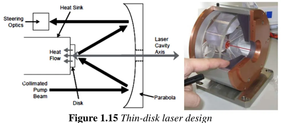
The core concept of the thin-disk laser principle is the usage of a thin, disk-shaped active medium that is cooled through one of the flat faces; simultaneously, the cooled face is used as folding or end mirror of the resonator. This face cooling minimizes the transversal temperature gradient and the phase distortions transversal to the direction of the beam propagation. This, in fact, is the basis of one of the outstanding features of the thin-disk laser: the excellent beam quality.
Figures 1.15 shows the principle of the thin-disk laser design. The laser crystal has a diameter of several millimeters (depending on the output power/energy) and a thickness of 100–200 μm depending on the
laser-active material, the doping concentration, and the pump design (Figure 2.2).
Figure 1.15 Thin-disk laser design
The disk is highly reflective coated on its backside for both the laser and the pump wavelengths and antireflective coated on the front side for both wavelengths. This disk is mounted with its backside on a water cooled heat sink using indium–tin or gold–tin solder. This technique allows a very stiff fixation of the disk on the heat sink without deformation of the disk. To reduce the stress during and after the soldering process, as much as possible, the heat sink is made from a heat expansion matched material (Cu–W). The heat sink is water cooled by impingement cooling using several nozzles inside the heat sink.
The crystal can be pumped in a quasi-end-pumped scheme. In this case, the pump beam hits the crystal under an oblique angle. Depending on the thickness and the doping level of the crystal, only a small fraction of the pump radiation is absorbed in the laser disk. Most of the incident pump power leaves the crystal after being reflected at the backside. By successive redirecting and imaging of this part of the pump power again onto the laser disk, the absorption can be increased.
A very elegant way to increase the number of pump beam passes through the disk is shown in Figure 1.16 The radiation of the laser diodes for pumping the disk is first homogenized either by fiber coupling of the pump radiation or by focusing the pump radiation into a quartz rod. The
end of either the fiber or the quartz rod is the source of the pump radiation, which is imaged onto the disk using the collimating lens and the parabolic mirror.
Figure 1.16 Pump design of the thin-disk laser
In this way, a very homogeneous pump profile with the appropriate power density in the disk can be achieved which is necessary for good beam quality. The unabsorbed part of the pump radiation is collimated again at the opposite side of the parabolic mirror. This beam is redirected using two mirrors to another part of the parabolic mirror where the pump beam is focused again onto the disk, this time from another direction. This reimaging can be repeated until all the (virtual) positions of the parabolic mirror have been used. At the end, the pump beam is edirected back to the source, thereby doubling the number of pump beam passes through the disk. In this way, up to 32 passes of the pump radiation through the disk have been realized and more than 90% of the pump power is absorbed in the disk.
Using multiple pump beam passes through the disk results in a thinner disk and/or a lower doping concentration, thus reducing the thermal effects like thermal lensing and stress in the disk. Another advantage is
that the effective pump power density is increased (nearly four times for 16 pump beam passes) so that, on the one hand, the demands to the power density (beam quality) of the pump diodes are reduced and, on the other hand, quasi-three-level laser materials (e.g., ytterbium doped) can also be used with this design.
1.6.2 Minimal thermal lensing effect
Due to the small thickness of the disk ( 100–200 μm), the temperature rise associated with the dissipated power is small. (It is not relevant that the density of heat generation is rather high, because the heat is generated very close to the heat sink.) In addition, the temperature gradients are dominantly in a direction perpendicular to the disk surface (Figure 1.17) and thus cause only weak thermal lensing and depolarization loss. This allows for operation with very high beam quality due to the weak thermal beam distortions, and stable operation can be achieved over a wide range of pump powers.
Figure 1.17 Difference temperature gradients between rod and disk
geometry
As mentioned earlier, the temperature gradients inside the laser crystal are mainly coaxial to the disk axis and the laser beam axis due to this mounting and cooling technique. The temperature in the radial direction is
nearly uniform within the homogeneously pumped central area of the disk. Therefore, these temperature gradients only slightly influence the laser beam propagation through the disk. All the thermal lens effects and aspherical parts of the profile of the index of refraction are reduced by more than one order of magnitude compared to rod laser systems. The stress-induced birefringence is even more reduced and can be neglected for real laser systems. Additionally, due to the large surface-to-volume ratio, the heat dissipation from the disk into the heat sink is very efficient thus allowing the operation at extremely high volume power densities in the disk (up to 1 MW/cm3 absorbed pump power density).
1.6.3 Scaling power regulation
Very high laser output power can be achieved from one single disk, by increasing the pump spot diameter while keeping the pump power density constant. Figure 1.18 shows the laser results (power and optical efficiency) from an Yb:YAG disk that has been pumped up to the same level of pump power density (about 4 kW/cm2) but with different pump spot diameters between 1.2 and 6 mm.
Figure 1.18 Laser results for different pump spot diameters (Yb:YAG,
It is obvious that the slope efficiency and the optical efficiency curves are similar. But, it is also clear that the laser threshold is increased with increased pump spot diameter; in fact, the threshold is proportional to the pumped area (or better: proportional to the number of laser ions). These measurements demonstrate clearly the power scaling capability of the thin-disk laser design. Figure 1.19 shows to our knowledge the highest output power from one disk. More than 5.3-kW power has been achieved with a maximum optical efficiency of more than 65%. This high efficiency of the thin-disk laser results also in a very high electrical efficiency of the total laser system which is higher than 25% for industrial lasers with 8 kW output power and a beam propagation factor M2 of less than 24.
Chapter 2
Laser Welding
2.1 Introduction
The focused laser beam is one of the highest power density sources available to industry today. It is similar in power density to an electron beam. Together these two processes represent part of the new technology of high-energy-density processing.
At these high power densities all materials will evaporate if the energy can be absorbed. Thus, when welding in this way a hole is usually formed by evaporation. This "hole" is then traversed through the material with the molten walls sealing up behind it. The result is what is known as a "keyhole" weld. This is characterized by its parallel sided fusion zone and narrow width. Since the weld is rarely wide compared to the penetration it can be seen that the energy is being used where it is needed in melting the interface to be joined and not most of the surrounding area as well. A term to define this concept of efficiency is known as the "joining efficiency”. The joining efficiency is not a true efficiency in that it has units of (mm2 joined/kJ supplied). It is defined as (V t / P), where V is the traverse speed (mm/s), t is the thickness welded (mm) and P is the incident power (kW). Table 2.1 gives some typical values of the joining efficiency of various welding processes.
The higher the value of the joining efficiency the less energy is spent in unnecessary heating - that is generating a heat affected zone (HAZ) or distortion. Resistance welding is by far the best in this respect because the energy is mainly generated at the high-resistance interface to be welded. However, it can be seen that the electron beam and laser are again in a class by themselves.