Department of Computer Science
Doctoral Program in Computer Science (XXXI Cycle)
Real-time and long lasting Internet of Things
through semantic wake up radios
Federico Ceccarelli
iii Thesis commitee
Prof. Chiara Petrioli (advisor) Department of Computer Science
Sapienza - University of Rome Rome, Italy
Prof. Enrico Tronci Department of Computer Science
Sapienza - University of Rome Rome, Italy
Prof. Gaia Maselli
Department of Computer Science Sapienza - University of Rome
Rome, Italy
External Reviewers Prof. Cristian Cassella
Department of Electrical and Computer Engineering Northeastern University
Boston, Massachusetts, USA Prof. Sergio Palazzo
Department of Electrical, Electronic and Computer Engineering University of Catania
Abstract
The world is going towards the Internet of Things (IoT) where trillions of objects that are common in our lives will be enhanced and revolutionized by adding them computational and networking capabilities. Examples are cars, street lamps, industrial machinery, electrical appliances. The corner-stone of Internet of Things research is Wireless Sensor Networks (WSNs). These networks are made of hundreds of low-cost, low-complexity devices endowed with sensors to monitor the surrounding environment or objects. Typically these devices (also called sensors, nodes or motes) are battery-powered, therefore they can operate for a limited amount of time (i.e., days) before running out of energy. This is the main challenge that applications of Wireless Sensor Networks have to face.
Since one of the major power consumers in a node is the radio transceiver, a lot of research effort has been put into finding solutions that keep the radio in a low-power state as much as possible, while not harming the commu-nication capability. While this approach brings the network lifetime, i.e. the time before battery-operated nodes die having depleted their energy, to years or more, it introduces significant latency, as the energy reduction comes at the cost of not being able to reach nodes in deep sleep for long period of times. The most promising solution to this problem is the wake-up radio, an additional ultra-low power transceiver used for the sole purpose of triggering the activation of the high power, high bandwidth radio. Wake-up radio enabled IoT systems maintain always on their wake up radio, which has a negligible energy consumption, in this way optimizing both energy and latency performance metrics. Most of the research so far focused on the design of wake-up receivers, while a limited amount of communication protocols that take advantage of this radio has been proposed. Moreover, almost all of these protocols have been evaluated only through simulations.
In this thesis we set to start filling this gap. We first evaluate the range performance of an ultra-low power wake-up receiver integrated into a state-of-the-art Wireless Sensor Network mote, the MagoNode++. Based on the results of this evaluation we deploy an outdoor testbed made of MagoN-ode++ motes. The testbed allows to validate in a real-world scenario our implementation of CTP-WUR, an extension of the widely used Collection Tree Protocol (CTP) for wake-up radio-enabled Wireless Sensor Networks. The comparison between CTP-WUR and CTP demonstrates that wake-up radios can effectively reduce the power consumption and obtain, at the same time, end-to-end latencies in the order of milliseconds, enabling new time critical applications. Based on the results and on the insights gained dur-ing the testbed evaluation a new version of CTP-WUR is presented that improves its performance across all the metrics taken into consideration: end-to-end packet latency, energy consumption and Packet Delivery Ratio.
Contents
1 Introduction 1
1.1 List of publications . . . 6
2 State of the art 7 2.1 Wake-up radio design . . . 7
2.2 Wake-up radio-enabled protocols . . . 10
3 Wake-up Radio Ranges: A Performance Study 15 3.1 Wake-Up Radio Receiver and mote architecture . . . 15
3.1.1 Wake-up radio receiver. . . 15
3.1.2 Mote architecture . . . 17
3.2 Scenarios and settings . . . 18
3.3 Investigated metrics . . . 19
3.4 Performance results . . . 20
3.4.1 868 MHz . . . 20
3.4.2 433 MHz . . . 21
3.5 Extended evaluation . . . 23
3.5.1 Range tests without Hamming encoding . . . 24
3.5.2 Range tests with Hamming encoding . . . 25
3.5.3 Range tests with receivers around the transmitter . . 27
3.6 Conclusions . . . 30
4 Wake-up radio-based WSNs: A networking performance evaluation via real-world testbed experiments 31 4.1 CTP . . . 31
4.2 CTP-WUR . . . 33
4.2.1 Improving CTP-WUR . . . 35
4.3 Experimental scenario and settings . . . 38 vii
4.4 Performance metrics . . . 42
4.5 Performance results . . . 42
4.5.1 End-to-end latency . . . 42
4.5.2 Energy consumption . . . 43
4.5.3 Packet Delivery Ratio . . . 45
4.6 Conclusions . . . 47
5 Concluding remarks 49
Chapter 1
Introduction
The advancements of the electronics in the last decade have made possible the realization of radio transceivers, microcontrollers, memories and sensors small enough (yet powerful) to be embedded inside objects that surround us in the everyday life, paving the way for new applications that can
en-hance our quality of life [1]. This is the so-called Internet of Things (IoT).
The Internet of Things appears in many different ways (e.g., Smart Cities or Industry 4.0) but one of the cornerstones is represented by Wireless Sen-sor Networks (WSNs): networks of low-cost and low-complexity devices, equipped with a variety of sensors and a radio transceiver that cooperate to measure some physical quantity in the real world. These devices (also called sensors, nodes or motes) create multi-hop, ad-hoc networks in order to forward the measured data towards one or more collection endpoints, the sinks.
Thanks to their flexibility they allow applications such as Structural
Health Monitoring of critical infrastructures [2] or smart healthcare
sys-tems [3]. Most of these applications have to face a challenge: they are made
of battery-powered devices, therefore the available amount of energy is lim-ited. In general, frequently replacing the batteries has a remarkable impact on the costs and, in some case, can be impractical. An example is a wireless sensor network made of some tens of devices monitoring the stability of a bridge. This challenge constitutes a major obstacle to long-term deploy-ments. For this reason, a lot of research has been done in order to increase the operational lifetime of wireless networks.
An approach to this problem is to harvest energy from the environment 1
using small solar panels or wind turbines to recharge the battery or a
super-capacitor [4,2]. On the other hand, the intermittent nature of these sources
of energy makes them impossible to rely on. Therefore, it is essential to try to reduce as much as possible the energy consumption of network nodes. The hardware component that draws the most energy is the radio transceiver, irrespective of its state, either transmitting or receiving. However, most of the time the radio is not busy in any of these two activities, but it listens on the channel for incoming transmissions. This is called idle listening. Since the traffic rate in this kind of networks is, in general, very low, keeping the radio active waiting for a transmission that may be minutes away is a waste of energy. Therefore, the goal is to keep it in a low-power mode as long as possible, where it consumes orders of magnitude less energy than in the active state. But, in the low-power state the radio is not able to receive anything.
Consequently there is a trade-off between energy consumption and com-munication capability. The established solution to this problem is to turn on and off periodically according to a pre-set duty-cycle the radio in order to allow communications only during certain time intervals. Several MAC protocols have been presented that follow this approach, each one trying to
optimize some aspect. There are protocols, called synchronized [5,6], where
each network node exchanges with its neighbors its wake-up schedule so that it knows when each one of them will activate its radio and will be able to receive. Other protocols are asynchronous: each node knows only its own
duty-cycle [7,8,6]. When it wants to transmit to a neighbor it has to
“inter-cept” its active period. To do that it precedes the actual packet transmission with a preamble long enough to be heard by the recipient the next time it will turn on its radio. Several different optimizations on the length and for-mat of the preamble have been proposed. This technique effectively reduces
power consumption, allowing network to be operative for several months [9],
but it has two drawbacks: i) it does not completely remove idle listening, which is only reduced, and ii) it increases packet latencies, because a node has to wait for the receiving node to activate its radio before actually trans-mitting the packet. On large deployments, the end-to-end packet latency can be in the order of seconds, making these protocols unfit for time critical applications (e.g., a WSN monitoring a bridge). It is clear that duty-cycling introduces a trade-off between energy efficiency and latency.
3
To remove this trade-off research has proposed the use of low-power trig-gering techniques, such as equipping network nodes with wake-up radios. A wake-up radio is an additional transceiver that flanks the main one, there-fore called main radio. It is designed to have a consumption comparable to that of the main radio when this is in its lowest-power state (called sleep state). Typical values of current consumption of a main radio in an active state (i.e., transmitting, receiving or idle listening) are in the order of few tens of mA. These values go down to few µA when the radio is put in the
sleep state [10, 11, 12]. With this approach the main radio is brought in
the active state only when it has to transmit or receive a packet. Instead, the wake-up radio is always active waiting for a specific signal (the wake-up signal ) to trigger the main radio activation.
Therefore the wake-up radio allows to completely remove idle listening
and, at the same time, keeps latencies low, in the order of milliseconds [13,
14,15].
In order to avoid that all the nodes inside the communication range of the wake-up radio activate their main transceiver, different addressing methods can be used. With identity-based addressing the wake-up signal contains the ID of the recipient. Semantic addressing allows to wake-up only the neighbors that have certain characteristics, described by metrics that are specific of the used protocol. Examples of metrics are the distance from the destination or the residual amount of energy of the node. Every network node has a pool of wake-up addresses that codify its status based on the chosen metrics. The wake-up signal contains the metrics values that a possible receiver should have.
So far the research on wake-up radio-enabled wireless sensor networking has focused mainly on the design of hardware that consumes as little en-ergy as possible. In general, to obtain the required ultra-low consumptions sensitivity and bitrate are sacrificed. This means that a wake-up radio re-ceiver has a shorter communication range and is slower than the main radio. New problems arise: for example routing paths are longer when wake-up ra-dios are used. In recent years, the wireless networking research community have started to present more protocols taking into account the capabilities and shortcomings of wake-up radios. This prompted also the IEEE 802.11 Working Group to start the process of standardization of wake-up radios.
(PHY) and Medium Access Control (MAC) layers of wake-up radio devices that are thought to be used together with traditional IEEE 802.11 devices in order to reduce their energy consumptions.
Almost all the protocols proposed so far have been evaluated through simulations. Only a few of them have been implemented and tested on real hardware. Simulations give many insights on the behavior of protocols, even on large scale networks, and allow to validate the ideas that under-pin their design. But when protocols are tested in a real-world environ-ment several new circumstances must be taken into account. To name a few of them: costs, coexistence with other wireless services (e.g., cellular networks, WLANs), hardware malfunctions, weather conditions. Therefore real testbeds available for wake-up radio-based networking are quite rare.
An example is the Flocklab [17].
In this thesis we will present the results of our research on wake-up radio-based wireless sensor networks using a real-world testbed. In order to build the testbed, it has been necessary to evaluate the wake-up range attainable by the MagoNode++, a state-of-the-art mote for WSNs that features an ultra-low power wake-up receiver. Then we evaluate our implementation of CTP-WUR, a protocol designed to adapt the leading routing protocol for data collection in WSNs, the Collection Tree Protocol (CTP). Its comparison against CTP with duty-cycle proves that wake-up radio technology can ef-fectively reduce energy consumptions and obtain end-to-end latencies in the order of milliseconds, paving the way for time critical applications. Thanks to the insights obtained through the testbed evaluation, we also propose, implement and validate an optimization of CTP-WUR that further reduces consumptions and latencies.
The rest of the thesis is organized as follows. In Chapter 2 we give a
general overview to the state of the art of the research on wake-up radio-enabled WSNs.
In Chapter 3 we evaluate the range performance of an ultra-low power
wake-up radio receiver (WuR) integrated into a wireless device suitable for wireless sensor networking deployments. We run several ranging experi-ments, both indoors and outdoors, where a transmitter sends wake-up se-quences to a receiver positioned meters away. We measure the amount of received sequences and whether they incur errors or not. Our experiments show that for distances up to 24 meters indoors the tested WuR receives
5
more than 96% of the transmitted sequences. The WuR performs slightly better outdoors, with more than 99% of the sequences being received with negligible amounts of errors.
In Chapter 4 we evaluate the effectiveness of wake-up radios in a
real-world multi-hop testbed. To this end, we implement CTP-WUR, an exten-sion of the Collection Tree Protocol (CTP), designed to take advantage of wake-up receivers. We also present a variation of CTP-WUR, that improves its performance. Both versions are compared, in our testbed, against CTP with duty cycle. The results of our experiments show that the use of wake-up radios produces remarkable energy savings (wake-up to 15 times) and achieves latencies that are up to 10 times lower than those achieved by CTP with duty cycled radios.
1.1
List of publications
In the following the papers accepted for publications or submitted for review that form the basis of this thesis are listed.
• S. Basagni, F. Ceccarelli, F. Gattuso, C. Petrioli. “Demo Abstract: Abating LPL-induced Latency with Wake-up Radio Technology”. In Proceedings of ACM/IEEE IoTDI 2017, Pittsburgh, PA, USA. April 18 – 21 2017.
• S. Basagni, F. Ceccarelli, C. Petrioli, N. Raman, A.V. Sheshashayee. “Wake-up Radio Ranges: A Performance Study”. In Proceedings of IEEE WCNC 2019. Marrakech, Morocco. April 15 – 19 2019.
• A journal paper with the results described in this thesis is currently in preparation.
Chapter 2
State of the art
This section provides a brief overview of the research on wake-up radio-enabled Wireless Sensor Networks, covering both hardware designs and net-working protocols. A broad survey of the field is presented by Piyare et al. in [18].
2.1
Wake-up radio design
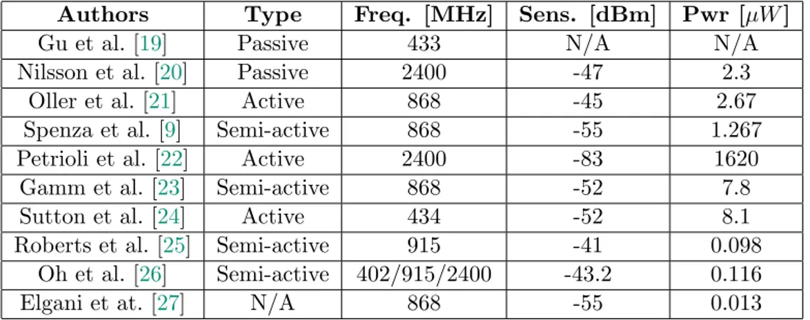
Over the last twenty years several wake-up radio receivers prototypes have been presented. In this section we will describe some of them (summarized
in Table2.1).
Table 2.1: Wake-up Radio Prototypes
Authors Type Freq. [MHz] Sens. [dBm] Pwr [µW ]
Gu et al. [19] Passive 433 N/A N/A
Nilsson et al. [20] Passive 2400 -47 2.3
Oller et al. [21] Active 868 -45 2.67
Spenza et al. [9] Semi-active 868 -55 1.267
Petrioli et al. [22] Active 2400 -83 1620
Gamm et al. [23] Semi-active 868 -52 7.8
Sutton et al. [24] Active 434 -52 8.1
Roberts et al. [25] Semi-active 915 -41 0.098
Oh et al. [26] Semi-active 402/915/2400 -43.2 0.116
Elgani et at. [27] N/A 868 -55 0.013
The first design of a wake-up radio was presented by Gu and Stankovic
in [19]: it is a passive circuit that harvests the power from the received radio
signal to generate a wake-up interrupt. It is evaluated through simulations showing that it reaches a wake-up range of 3 meters, enough for short-range applications such as Wireless Body Area Networks (WBANs), but insuffi-cient for the typical applications that require longer ranges. Another way to realize a completely passive wake-up receiver is using RF-powered RFID
tags, as in [28] and [29]. They have a wake-up range of around 10 meters,
a typical value for UHF RFID systems [30]. This kind of solutions, however,
are not suited for applications that require peer-to-peer communications be-tween the nodes. In fact, in order to transmit a wake-up sequence, a RFID reader is required, which has a power consumption in the order of Watts.
To have higher wake-up range, it is necessary to allow that some parts of the circuitry drain current from the battery. Typical solutions use Schottky diodes, MOSFETs or ad-hoc ICs to implement the envelope detector and a low-power comparator to generate the wake-up interrupt. In this way higher sensitivities can be obtained. For example, the design proposed by Nilsson
et al. [20] reaches a -47 dBm sensitivity with a power consumption of 2.3µW .
Oller et al. [21] presented a wake-up receiver featuring a -45 dBm
sensitiv-ity and a current consumption lower than 1µA; in their measurements the
wake-up range was above 10 meters. Spenza et al. [9] presented a
semi-active wake-up receiver with an ultra-low power consumption of 1.276µW and addressing capabilities. The wake-up signal is modulated using the On-Off Keying (OOK) scheme. This allows to keep the design of the receiver simple, which can be seen as made of four parts: the matching network, the envelope detector, the comparator (the only active component) and a preamble detector. An optional ultra-low power microcontroller can be used to perform address matching. The maximum sensitivity that has been mea-sured is -55 dBm. The authors tested several data rates, from 1 kbps up to 100 kbps and measured the maximum wake-up range attainable: 45 meters when they considered only the capability of generating the wake-up
inter-rupt and 32 meters for selective awakenings. Petrioli et al. in [22] presented
a wake-up receiver prototype operating in the 2.4 GHz band, with selective addressing capability. In their design nodes are addressed using a sequence of continuous-wave or narrow-band pulses on a combination of some the 16 channels established by the IEEE 802.15.4 standard on the 2.4 GHz band.
2.1. WAKE-UP RADIO DESIGN 9
This architecture has a sensitivity of -83 dBm, which allowed to obtain a wake-up range of 120 meters in outdoor in-field experiments. Its power consumption is 168µW .
Paoli et al. [31] presented the MagoNode++, a WSN platform for Energy
Neutral applications. It integrates the wake-up radio presented in [9] with
a light or thermoelectric energy harvester and with a battery and power
management module. Bedogni et al. [32] presents the architecture of a new
Wake-up Radio IoT node. It uses a wake-up radio receiver designed by STMicroelectronics that operates in the 868 MHz frequency band. This receiver can be powered either by the node’s battery (i.e., it is an active receiver) or by the RF signal (i.e., it is passive). In the first case it has a sensitivity of −38 dBm, while in the latter case it reaches −18 dBm. Moreover this architecture supports two operative modes: in the first one, called Switch mode, the node can be completely shut down using a hardware switch, reducing to zero the power consumption (plus the eventual power consumption of the wake-up receiver, if operating in an active way). This means that when the node receives a wake-up signal, it incurs in the addi-tional overhead, both in terms of energy and time, of the boot phase. In the second operative mode, called Low power mode, the mote is put into a deep sleep state, hence continuously consuming a minimum amount of en-ergy, and when it receives a wake-up signal an interrupt awakes the MCU moving it into an active state. These operative modes can be selected via software and the authors show how the choice on which one is best suited for an application, depends on how often a node should be activated during its operational lifetime.
There also exist off-the-shelf wake-up receivers, like the AS393X series
from Austria Microsystems [33]. They are low-power low-frequency
Am-plitude Shift Keying (ASK) wake-up receivers which generate an interrupt when a signal at a carrier frequency between 110 kHz and 150 kHz is de-tected. They are equipped with correlators able to detect 16-bit or 32-bit programmable wake-up sequences. Therefore they can support semantic ad-dressing. This family of receivers has a current consumption that varies from 1.37µA up to 2.7µA in listening mode and from 5.3µA to 8.3µA in active mode. They are used in the design of the receivers presented by Gamm et
al. in [23] and Sutton et al. in [24]. The latter is also used to receive data
that allowed ranges up to 15 meters in non-line-of-sight indoor experiments and up to 30 meters in line-of-sight outdoor experiments.
Some proposed designs feature nano-power consumptions. However they have very short wake-up ranges, that make them unfit for general sensing systems applications. An example is the receiver presented by Roberts and
Wentzloff [25], which has a power consumption of 98 nW, but its wake-up
range is at most 1.2 meters when the signal is transmitted at 0 dBm using patch antennas. Another receiver architecture with nano-power
consump-tions (specifically, 116 nW) has been presented by Oh et al. [26]. To avoid
false awakenings their wake-up radio adopts two mechanisms: the first is to support addressing through the use of a 32-bit OOK-modulated CDMA code; the second is an automatic threshold feedback that detect the pres-ence of interferpres-ence sources and dynamically adapt the receiver’s sensitivity. The authors tested the radio in three different frequency bands: the 402-405 MHz MICS band (Medical Implant Communication Service), the two ISM bands 915 MHz and 2.4 GHz. In these bands they measured the following sensitivities: -45 dBm (403 MHz), -43 dBm (915 MHz) and -41 dBm (2.4 GHz). They do not provide any actual wake-up range measurement. The
bitrate of this radio is 12.5 kbps. Elgani et at. [27] presented an integrated
circuit architecture for a wake-up receiver operating at 868 MHz with a 1 kbps bitrate. According to their simulations the integrated circuit can ob-tain the same sensitivity of WURs built with discrete components, i.e., -55 dBm, at the much lower power consumption of 13 nW.
A promising line of research on wake-up radio hardware envision the use of microelectromechanical systems (MEMS) for the realization of radio
frequency components. In [34] Zhu et al, presented a resonant switch suitable
to use in near-zero power RF wake-up receivers. This device showed a
sensitivity of -8 dBm.
2.2
Wake-up radio-enabled protocols
Even though most of the research has been focused on new hardware re-ceivers, both MAC, routing and cross-layer protocols designed to work with
wake-up radios have been presented in the past years. Table2.2summarizes
the networking protocols that we survey in this section.
mech-2.2. WAKE-UP RADIO-ENABLED PROTOCOLS 11
Table 2.2: Wake-up radio-enabled networking protocols
Protocol Type Implementation
STEM [35] MAC Simulation
WUR-MAC [36] MAC Simulation
Stathopoulos et al. [37] Routing Testbed
ALBA-WUR [9] Cross-layer Simulation
FLOOD-WUP [22] Routing Simulation
GREEN-WUP [22] Cross-layer Simulation
CTP-WUR[38] Routing Simulation
GreenRoutes [39] Cross-layer Simulation
WHARP [40] Cross-layer Simulation
T-ROME [41] Cross-layer Testbed
Zippy [24] Cross-layer Testbed
OPWUM [42] Cross-layer Simulation
anisms for energy savings is STEM [35]. Two versions of STEM were
pro-posed: STEM-T where the wake-up signal is just a tone and STEM-B where the wake-up signal contains the address of the destination node. Since at that time ultra-low power radios did not exist, the authors proposed to use two main radios, operating on different frequencies: one acting as a real main radio (i.e., transmitting data packets and being active only when needed) and the other one acting as a wake-up receiver. In order to have a low en-ergy consumption by this second radio, it followed a very low duty-cycle. For this reason STEM does not solve the problems of known duty-cycling MAC
protocols. WUR-MAC [36] is a simple MAC protocol that implements the
well-known RTS/CTS handshake mechanism on wake-up radios. It requires that main and wake-up radio operate on the same frequency band, because the channel access packets are sent by the former and received by the lat-ter one. It supports both unicast and broadcast communications, since the wake-up packet contains the destination address. It also supports channel selection, as sender and receiver use the RTS and CTS packets to agree on one of them.
The protocol presented by Stathopoulos et al. [37] considers a dual radio
system where each node uses the low-power radio to request to a central node, called “topology controller” the end-to-end path to the destination. The controller, which is aware of the main radio paths between all the pair
of nodes, uses the low-power radio to send back the path to the sender node and to wake-up all the nodes along the path. The wake-up addressing is ID-based. The data packets forwarding is handled by the high bandwidth radio.
Spenza et al. in [9] presented ALBA-WUR, a cross-layer protocol for
data collection in networked sensing systems. The authors redesigned
ALBA-R [43] to take advantage of the features of wake-up radios, and in particular
of semantic addressing. This technique allows to represent the complex re-lay selection policy of ALBA-R in a pool of wake-up addresses which is dynamically updated by the nodes, depending on their status. In ALBA-R the next-hop selection is based on some parameters: the possible advance-ment towards the sink (represented by the Geographic Priority Index, GPI), whether the neighbor is congested and how good it forwarded past packets (represented by the Queue Priority Index, QPI) and whether the neighbor is on a path towards a dead end (represented by a color). In ALBA-WUR every node creates a pool of wake-up addresses that represent all the pos-sible combinations made of the QPI values it can satisfy, all the pospos-sible number of packets it can hold in its buffer and all the possible colors that nodes must have in order to forward packets to it. In this way a node wakes-up only those neighbors that satisfy the forwarding policy, i.e. only
those whose current status makes them the best relay. Petrioli et al. in [22]
presented two protocols that exploit semantic addressing to improve system performance: FLOOD-WUP and GREEN-WUP. FLOOD-WUP is an en-ergy efficient flooding protocol where nodes dynamically change their wake-up address to avoid being woken wake-up by the retransmissions of packets they have already received. GREEN-WUP is a converge-casting protocol where the wake-up address of each node reflects its hop count from the network sink and its energy status (i.e., the remaining energy in the battery and the amount harvested from the environment, if any). The protocol chooses the next-hop with an RTS/CTS exchange, where the RTS is actually the wake-up request. The transmitting node sends a wake-up request containing the desired hop count (i.e., its distance from the sink - 1) and the desired energy level. If any neighbor satisfies this condition, it has the correspond-ing wake-up address, therefore it wakes up and replies with the CTS. Then the sender node selects the next-hop among all the neighbors that replied.
2.2. WAKE-UP RADIO-ENABLED PROTOCOLS 13
facto standard in WSN data collection routing, to make it work on wake-up radio-enabled wireless sensor networks. This protocol, called CTP-WUR, tackles the problem of the shorter range of WURs compared to the main radios. To virtually extend the wake-up range it enables relaying of wake-up sequences. In this way the node that will be woken up is not the parent in the routing tree, but the parent of the parent, which is assumed to be inside the range of the main radio. Thanks to this, CTP-WUR is able to reduce the number of hops needed to reach the sink and end-to-end latencies. Basagni
et al. in [39] presented GreenRoutes, a cross-layer protocol for Wireless
Sensor Networks with energy-harvesting and wake-up radio capabilities. In GreenRoutes a node chooses the next-hop through a RTS/CTS exchange. The selection is based on the distance from the sink and on the remaining energy along recently used routes to the sink. Thanks to semantic addressing only those neighbors that satisfy the requirements of the forwarding policy
are woken up. In [40] Basagni et al. presented WHARP a cross-layer
proto-col for Wireless Sensor Networks with energy-harvesting and wake-up radio capabilities. In WHARP semantic addressing is used to wake-up neighbors that are closer to the sink: the wake-up address of each node is its distance in hops from the sink. When a node receives a wake-up request with a matching address, it decides whether to activate its radio and participate in the RTS/CTS exchange using a Markov Decision Process (MDP) based on the forecast energy and expected traffic load.
Kumberg et al. [41] presented a cross-layer data forwarding protocol:
T-ROME. It uses RTS/CTS packets to reduce collisions over the wake-up messages. It is based on a tree routing algorithm: a node can send a wake-up packet only to its parent, wake-up until it reaches the destination. A data packet, instead, can cross several levels of the routing tree, thanks to the main radio longer range, saving energy of the intermediate nodes. Two
optimizations of T-ROME are proposed by Kumberg et al. in [44]: they
allow significant savings in terms of energy consumptions and overhead. The first optimization avoids the transmission of MAC acknowledgements during the route establishment phase: this reduces the overhead of the protocol and the probability of a communication failure, because less packets are exchanged. The second optimization tackles the problem of the nodes that get disconnected from the network because their parents in the routing tree are temporarily unreachable or have run out of energy. In this case they can
reconnect to the rest of the network if a parent of the disappeared node is within their wake-up range.
In [24] Sutton et al. introduced Zippy, an on-demand flooding protocol.
Zippy can be seen as made of three phases. The first one is asynchronous network wake-up, where all the nodes in the multi-hop network are woken up. The second is neighborhood synchronization, that allows fine-grained per-hop synchronization in the order of few tens of microseconds. Then, there is bit-level data dissemination. To avoid destructive interference due to concurrent transmissions, carrier frequency randomization is used. The protocol has been validated in the multi-hop testbed FlockLab. Aoudia et
al. [42] presented OPWUM, a cross-layer protocol exploiting wake-up radios
to opportunistically select the next hop relay. It generalizes the concept of timer-based contention mechanism: in fact the authors do not specify any metrics according to which the choice should be made, leaving it to be defined depending on the specific application. The RTS/CTS exchange happens completely through the wake-up radio.
Chapter 3
Wake-up Radio Ranges: A
Performance Study
To build a testbed for wake-up radio-based wireless sensor networking, it is necessary to know how far a wake-up signal can be heard by the wake-up receiver used. In this chapter the results of the performance evaluation of a wake-up radio receiver prototype are showed and discussed. The evaluation consists in several ranging experiments, both indoors and outdoors, where a transmitter sends a set of wake-up sequences to a receiver positioned meters away. Every received sequence is compared against the transmitted one
to check whether it has incurred errors or not. In Section 3.1 the wake-up
radio design and the wireless mote used are described. Section3.2details the
experimental setup, while Section3.3presents the investigated performance
metrics. In Section 3.4 and Section 3.5 the results of the experiments are
presented.
3.1
Wake-Up Radio Receiver and mote
architec-ture
3.1.1 Wake-up radio receiver
The architecture of the WuR used in this work is depicted in Figure3.1[9].
In this section we summarize its main components.
The receiver uses the On-Off Keying (OOK) modulation, one of the
simplest forms of Amplitude-Shift Keying modulation. Digital data are
Antenna C1 L1 Matching network C2 HSMS-285C HSMS-285C C3 Vcc TLV3701 R1 C4 Data SD3 R2 C5 Wake-up R3 Ultra-low power microcontroller Wake-up interrupt Communication SPI / I2C Optional Passive rectifier Envelope detector
Interrupt generator / Addressing
Comparator with adaptive threshold
Preamble detector Interrupt and data
Sensor node
Figure 3.1: Architecture of the wake-up receiver [9].
represented as the presence or absence of a carrier wave.
The first component is the matching network : it maximizes the power transfer from the antenna to the rest of the circuit. It consists of an LC filter, whose components are set based on the transmission frequency. In this work, we tested two different prototypes of the WuR, optimized to work either in the 868 MHz frequency or in the 433 MHz frequency.
The output of the matching network is an RF signal from which infor-mation (i.e., the wake-up sequence) can be recovered. This task is carried out by the next two components. The passive envelope detector discards the frequency and phase content of the modulated waveform and only de-tects its amplitude, consistent with using OOK modulation. In the tested prototypes it consists of a single-stage half-wave rectifier with series diodes. In particular, the HSMS-285C diodes from Avago Technologies were used. They are optimized for sub-GHz frequencies and for incoming power levels lower than −20 dBm. They achieve a sensitivity of −57 dBm.
Once the signal is rectified, the bits of the received wake-up sequence are reconstructed by using an ultra-low power comparator. In order to reduce the static power consumption of the circuit, an adaptive threshold mechanism
keeps the V− pin of the comparator at half of the input signal level. This
allows to avoid the use of a voltage divider, as the threshold is generated using the energy coming from the antenna. The choice of the comparator influences the power consumption of the WuR, because it is the only active component of the design, as well as its overall sensitivity. In fact, compara-tors with a lower voltage offset are able to sense smaller signals. However, such comparators typically have higher current consumption. The consid-ered prototypes feature the TLV3701 comparator from Texas Instruments, which has a reasonable current consumption of 560 nA.
3.1. WUR AND MOTE ARCHITECTURE 17
The last component of the WuR is the preamble detector. It is used to filter out interference due to noise or other communications that can trigger unwanted awakenings. For this purpose, a preamble is added at the beginning of the wake-up sequence. The preamble is an OOK modulated signal representing a specific sequence of bits that is sent at a specific bit rate
fp. On-off keyed modulated signals that are sent at a data rate lower than
fp are discarded by the RC section of the preamble detector, which works as
a low-pass filter. If a preamble is received at the fp bit rate, the preamble
detector generates a wake-up interrupt to either the sensor node’s MCU or to an optional on-board ultra-low power micro-controller that reads data directly from the output of the comparator and performs address matching. The optional ultra-low power micro-controller (e.g., the PIC12LF1552
from Microchip [45]) relieves the sensor node of the wake-up address
recog-nition task and allows it to remain in the sleep state until a valid address is received. Hence, it decreases the total energy consumption.
This design obtains desirable characteristics for a WuR, namely, very low power consumption (< 1.3 µW) and high sensitivity (up to −55 dBm).
3.1.2 Mote architecture
In our experiments we used the MagoNode++ [31], a wireless mote designed
for WSN applications, which features the wake-up radio receiver described
in Section 3.1.1. Figure 3.2shows a snapshot of a MagoNode++ featuring
the WuR prototype on top of the casing used in our experiments.
The MagoNode++ is a low-power wireless mote equipped with a micro-controller/transceiver bundle. The microcontroller is based on a 8-bit, 16 MHz CPU featuring 256 KB of ROM and 32 KB of RAM. The integrated transceiver is a 2.4 GHz, 802.15.4 compliant radio module connected to a radio front-end that gives higher radio performance with low-power con-sumption. The wake-up extension board designed for the MagoNode++ is made up of two main components: The wake-up transmitter and the WuR. As mentioned, these components differ depending on the wake-up frequency used, namely, 868 MHz or 433 MHz. The wake-up transmitter is based on the CC1101 transceiver from Texas Instruments, a low-power sub-1 GHz
transceiver that supports OOK modulation [10]. The wake-up receiver is
the one described in Section 3.1.1. Wake-up transmitter and receiver use
Figure 3.2: A MagoNode++ mote with a WuR.
frequency. The two wake-up antennas are connected to the wake-up trans-mitter and to the WuR circuitry. In order to avoid any distortion of the emitted electromagnetic fields, in our experiments we keep these two anten-nas at a distance δ higher than the near-field distance, which depends on the frequency and on the size of the antenna. The impedance matching of the RF section was carefully designed to provide the maximum power transfer between the antenna and the rest of the circuit. Details on the tuning of
the matching network have been presented in [46]. The designers also chose
to use separate antennas for the wake-up system and the main radio (which is integrated in the MagoNode board) for greater accuracy in assessing the performance of the WuR. Wake-up signals generated by the WuR are sent to the MagoNode++ through a low-level asynchronous interrupt pin of the microcontroller. Asynchronous interrupts are able to wake-up the MagoN-ode++ from the dormant state, in contrast with synchronous interrupts that can be triggered only when the node is in idle mode.
3.2
Scenarios and settings
In our experiments we used the MagoNode++ mote with WuR capabilities
3.3. INVESTIGATED METRICS 19
and at 433 MHz.
We measure WuR range performance by placing a sender node S and a receiver node R at a given distance d, with d varying in {3, 6, 9, . . . , 24} meters. We consider both indoor and outdoor settings, all located within the premises of the Computer Science department of the University of Rome “La Sapienza,” Italy. Our indoor experiments were performed in a corridor
of the building (Figure3.3). The outdoor space is the building courtyard.
Figure 3.3: Indoor setting.
Sender and receiver exchange wake-up sequences each 8 bits long. Be-cause of hardware constraints, the sequences contain no six 1 in a row. This results in 248 viable sequences that can be received by the WuR.
Each sequence is preceded by a 4-bit preamble to allow the WuR to signal the wake-up interrupt needed to start the address matching phase. The transmission power of the wake-up sequences is set to 10 dBm.
3.3
Investigated metrics
We selected 50 among all viable sequences. Each selected sequence s is set as the wake-up sequence of node R. Node S then sends sequence s to node R. This is repeated 25 times in total, with each copy being sent every 100 ms.
For each sequence, we measure the following:
1. Sequences delivered : The percentage of sequences received by node R. 2. True positives: The percentage of sequences received correctly (node R
would correctly wake-up).
3. False negatives: The percentage of sequences received incorrectly (node R would not wake-up while it should).
In order to evaluate the likelihood that a transmitted wake-up sequence is modified into another valid one by the channel interference, causing an un-wanted wake-up (i.e., a false positive), we do the following. Each sequence s
is transformed into a sequence s0 by flipping one of its bits, chosen randomly.
If s0 is not a viable sequence (i.e., it contains six 1 in a row) it is discarded,
and a new sequence s0 is created. If s0 is viable, node S sends sequence s0
to node R. This is repeated 25 times, with one transmission every 100 ms. For each flipped sequence, we measure the following:
1. Flipped sequences delivered : The percentage of sequences s0 received
by node R.
2. True negatives: The percentage of sequences s0that have been received
different from sequence s (node R would correctly stay asleep).
3. False positives: The percentage of sequences s0 that have been received
incorrectly as sequence s (node R would wake-up while it should not). The results show the average of the outcomes of 5 repetitions of the experiment at each distance d.
3.4
Performance results
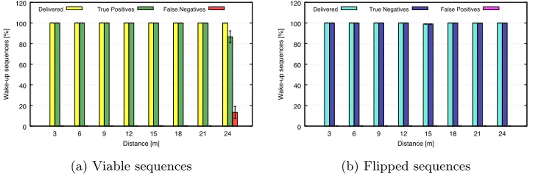
3.4.1 868 MHzResults of indoor experiments are shown in Figure3.4a and Figure3.4bfor
viable and flipped sequences, respectively.
The percentage of delivered sequences is above 96% over all the distances. False Negatives are consistently under 1% except when the distance between sender and receiver is 9 meters. In this case 2.5% of the sequences incur errors. False Positives are negligible.
3.4. PERFORMANCE RESULTS 21 0 20 40 60 80 100 120 3 6 9 12 15 18 21 24 Wake-up sequences [%] Distance [m]
Delivered True Positives False Negatives
(a) Viable sequences
0 20 40 60 80 100 120 3 6 9 12 15 18 21 24 Wake-up sequences [%] Distance [m]
Delivered True Negatives False Positives
(b) Flipped sequences
Figure 3.4: Indoor scenario, 868 MHz.
Results of outdoor experiments are shown in Figure3.5aand Figure3.5b
for viable and flipped sequences, respectively.
0 20 40 60 80 100 120 3 6 9 12 15 18 21 24 Wake-up sequences [%] Distance [m]
Delivered True Positives False Negatives
(a) Viable sequences
0 20 40 60 80 100 120 3 6 9 12 15 18 21 24 Wake-up sequences [%] Distance [m]
Delivered True Negatives False Positives
(b) Flipped sequences
Figure 3.5: Outdoor scenario, 868 MHz.
At least 99.97% of the sent sequences were delivered to the receiver. These sequences were almost always correctly detected, since False Negatives are consistently under 0.2%. The only False Positives have been observed at 18 meters in an insignificant amount (0.02%).
3.4.2 433 MHz
Results of indoor experiments are shown in Figure3.6a and Figure3.6bfor
viable and flipped sequences, respectively.
The percentage of delivered sequences is above 96% over all the distances. At 15 and 18 meters there is a small amount of False Negatives, i.e., of viable sequences received with some errors: 1.48% and 3.84%, respectively. At the same distances there is also a significant increase in the variance of the results.
0 20 40 60 80 100 120 3 6 9 12 15 18 21 24 Wake-up sequences [%] Distance [m]
Delivered True Positives False Negatives
(a) Viable sequences
0 20 40 60 80 100 120 3 6 9 12 15 18 21 24 Wake-up sequences [%] Distance [m]
Delivered True Negatives False Positives
(b) Flipped sequences
Figure 3.6: Indoor scenario, 433 MHz.
Results of the outdoor experiments are shown in Figure 3.7a and
Fig-ure3.7bfor viable and flipped sequences, respectively. At least 99.92% of the
0 20 40 60 80 100 120 3 6 9 12 15 18 21 24 Wake-up sequences [%] Distance [m]
Delivered True Positives False Negatives
(a) Viable sequences
0 20 40 60 80 100 120 3 6 9 12 15 18 21 24 Wake-up sequences [%] Distance [m]
Delivered True Negatives False Positives
(b) Flipped sequences
Figure 3.7: Outdoor scenario, 433 MHz.
transmitted sequences were delivered to the receiver. The viable sequences were almost always correctly detected up to 21 meters (a negligible amount of False Negatives has been observed at 15 and 18 meters). At 24 meters the performance begins to degrade, as 13% of the sequences incurs errors. During both indoor and outdoor experiments no False Positives have been received.
In general, for practical purposes both prototypes work well up to 21 meters. This provides us with a distance that can be safely used in larger testbeds and in simulation models. The slightly worse results in the indoor scenario are to be ascribed to the environmental noise.
3.5. EXTENDED EVALUATION 23
3.5
Extended evaluation
To further evaluate the wake-up range performance of the MagoNode++ mote, we performed more experiments. This set of experiments gives more insights on how the WuR performs in scenarios with different levels of noise and interference and whether it is affected by the relative position between sender and receiver. We also evaluated how Hamming-encoding the wake-up sequences affects the wake-wake-up ranges. The experiment setwake-up is the one
described in Section 3.2, but with two differences:
• We used two different indoor environments, one with a high level of noise and another with a low level of noise
• We tested the 868 MHz prototype.
We used the same 50 sequences of the previous experiments. Each se-lected sequence s is set as the wake-up sequence of node R. Node S then sends sequence s to node R. This is repeated 25 times in total, with each copy being sent every 100 ms. For each sequence, we measure the following metrics:
• True positives: The percentage of sequences received correctly (node R would wake-up)
• False negatives: The percentage of sequences received incorrectly (node R would not wake-up while it should)
• Spurious messages: The percentage of noise wake-up sequences re-ceived over the total number of rere-ceived sequences.
The results are averaged over 5 repetitions at each distance d.
The high noise scenario is the same indoor corridor of the experiments
of Section 3.4: it is located at the last floor of the building, therefore it is
exposed to external sources of interference. The low noise scenario is another corridor in the same building, but located at a lower floor, therefore more protected by the surrounding buildings. The outdoor scenario is the same: the courtyard of the building.
3.5.1 Range tests without Hamming encoding
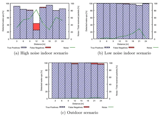
Figure 3.8a, Figure 3.8b and Figure 3.8c show, respectively, the results of
the indoor tests in a high noise scenario and in a low noise scenario and the results in an outdoor scenario, when the wake-up sequence is not
Hamming-encoded (as in Section 3.4). In this case the length of the transmitted
messages is 2 bytes: the first contains the preamble and the second the actual wake-up sequence.
0 20 40 60 80 100 3 6 9 12 15 18 21 24 0 20 40 60 80 100 Detected wake-ups [%] Noise / Total received packets [%] Distance [m]
True Positives False Negatives Noise
(a) High noise indoor scenario
0 20 40 60 80 100 3 6 9 12 15 18 21 24 0 20 40 60 80 100 Detected wake-ups [%] Noise / Total received packets [%] Distance [m]
True Positives False Negatives Noise
(b) Low noise indoor scenario
0 20 40 60 80 100 3 6 9 12 15 18 21 24 0 20 40 60 80 100 Detected wake-ups [%] Noise / Total received packets [%] Distance [m]
True Positives False Negatives Noise
(c) Outdoor scenario
Figure 3.8: Results of range experiments - Without Hamming encoding In the same indoor scenario of the previous experiments the percentage of transmitted wake-up sequences that have been received is above 90% only two times, at 3 and 18 meters. At 12 meters the worst performance of the wake-up receiver has been recorded: 43.5% of the transmitted sequences be-ing received and 24.8% of True Positives. The percentage of noise messages over the total number of received wake-ups goes from 26% at 18 meters to 82% at 12 meters. On average, over all the distances, 50.7% of the received wake-up sequences was noise. As we can see from the figures the percentage of detected sequences is inversely proportional to the noise messages.
3.5. EXTENDED EVALUATION 25
were delivered to the receiving node across all the distances. True positives are consistently above 97% with a slight decrease to 94.2% when the distance between the two nodes is 21 meters. This corresponds to the maximum value of the percentage of spurious messages received (28.4%).
In the outdoor scenario the percentage of received wake-up sequences is above 97% across all the distances. True Positives are consistently above 99%, with the exception of 12, 21 and 24 meters, where False Negatives amount to, respectively, 2%, 3% and 2.3%. Spurious messages are below 3%.
The lower amount of received sequences in the high-noise scenario is explained by the higher percentage of spurious messages received. In fact, if the wake-up receiver is triggered during the interval between two consecutive transmissions of a wake-up sequence (set at 100 ms), it may not be able to start receiving a real wake-up sequence. In general, in both scenarios, the presence of noise affects the ability to receive at all a wake-up sequence, while it does not have a big impact on the False Negatives, that are, in general, below 1%. Instead, at 12 meters in the high noise scenario, False Negatives are 18.8%, while the spurious sequences are 82% of the total amount of received sequences. We noticed that 12 meters in the high-noise corridor correspond to the only position where the receiving MagoNode++ has a window on both sides, while at all the other positions there is at least one wall. Since the corridor is located at the last floor of the building, that position is the most exposed to external interference. The most probable source of interference at 868 MHz is some 4G-LTE base station operating on the 800 MHz band (from 791 MHz to 862 MHz). This explains the different level of noise between the last floor of the building and the lower floor and the courtyard, that are more protected by the surrounding buildings.
3.5.2 Range tests with Hamming encoding
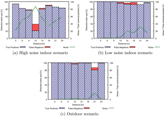
Figure 3.9a, Figure 3.9b and Figure 3.9c show, respectively, the results of
the indoor tests in a high noise scenario and in a low noise scenario and the results in an outdoor scenario, when the wake-up sequence is Hamming-encoded. The total length of the transmitted messages is 4 bytes. The first byte is the preamble. The second byte contains sync bits. The actual encoded wake-up sequence occupies the last two bytes. In fact, the H(8, 4) Hamming code used by the MagoNode++ takes 4 bits of data and produces
a 8 bit codeword. Hence, the 8-bit wake-up sequence becomes 16 bits long. 0 20 40 60 80 100 3 6 9 12 15 18 21 24 0 20 40 60 80 100 Detected wake-ups [%] Noise / Total received packets [%] Distance [m]
True Positives False Negatives Noise
(a) High noise indoor scenario
0 20 40 60 80 100 3 6 9 12 15 18 21 24 0 20 40 60 80 100 Detected wake-ups [%] Noise / Total received packets [%] Distance [m]
True Positives False Negatives Noise
(b) Low noise indoor scenario
0 20 40 60 80 100 3 6 9 12 15 18 21 24 0 20 40 60 80 100 Detected wake-ups [%] Noise / Total received packets [%] Distance [m]
True Positives False Negatives Noise
(c) Outdoor scenario
Figure 3.9: Results of range experiments - With Hamming encoding In both scenarios higher values of spurious wake-ups have been received compared to the experiments without Hamming encoding discussed in
Sec-tion 3.5.1. This affects the results, especially in the low-noise scenario,
where slightly higher levels of False Negatives have been received, with re-spect to the results of the experiments with no Hamming encoding.
In the low noise scenario more than 92% of the transmitted sequences were delivered to the receiving node across all the distances. True positives are above 95% from 3 to 12m and at 24m. Between 15 and 21m, in cor-respondence of higher values of noise (between 15% and 32% of the total number of received sequences), True Positives are between 92% and 93%.
Also in this case, in the high noise scenario the percentage of received wake-up sequences is above 90% only at 3 and 18m, while at 12m only 38% of the transmitted sequences were received, due to the high percentage of spurious sequences (87%). Only at 3m more than 90% of the transmitted wake-up sequences were correctly received.
3.5. EXTENDED EVALUATION 27
99% across all the distances, with the exceptions of 12 and 21 meters. The percentage of received sequences almost corresponds to the percentage of
True Positives, because wrong sequences are always less than 0.5%. At
21 meters the True Positives fall down to 80%, with a percentage of False Negatives of 6.4%. This happened in correspondence with a “spike” of noise messages, that totaled the 17% of the total amount of received sequences.
We can conclude that, at least in these simple experiments where just one node sends wake-up sequences to another one, the Hamming encoding does not give any remarkable advantage that can justify the longer transmission time. In the high-noise scenario the levels of interference may be too high for a code that can correct only one wrong bit to be effective.
3.5.3 Range tests with receivers around the transmitter
With these experiments we wanted to understand whether the relative posi-tion (i.e., the angle) between the transmitter and the receiver has some effect on the percentage of wake-up sequences received correctly. We placed 8 dif-ferent MagoNode++ motes around the transmitter in a wide open area in
the Villa Borghese gardens in Rome, Italy. Figure3.10shows how the nodes
were placed; the arrows show the side of the antennas on the motes. The distance d between sender and receivers varies in {3, 6, 9, . . . , 21} meters.
0° 90° 180° 270° Transmitter 225° 315° 45° 135°
Figure 3.10: Positions of the nodes during the experiments
re-spectively in terms of True Positives and Noise wake-ups, when no Hamming encoding was used. Up until 15 meters the percentage of True positives is consistently above 98% from all the angles around the sender.
0 20 40 60 80 100 3 6 9 12 15 18 21 True Positives [%] Distance [m] 0° 45° 90° 135° 180° 225° 270° 315°
(a) True Positives
0 20 40 60 80 100 3 6 9 12 15 18 21 Noise [%] Distance [m] 0° 45° 90° 135° 180° 225° 270° 315° (b) Noise
Figure 3.11: Receivers around the transmitter without Hamming encoding.
At 18 meters the percentage of True Positives stays on the same level
at all the angles with the exception of 270◦, where it falls at 72.6%. At
21 meters the percentage of True Positives at 270◦ falls to 50%. Also at
180◦ and 225◦ the percentage of correctly received wake-up sequences starts
to decrease: 92% and 85%, respectively. At all the other angles it remains above 98%. During all these experiments interference has almost never been
a real concern. Only the node placed at 270◦ at 21 meters seemed to be
3.5. EXTENDED EVALUATION 29
Figure 3.12a and Figure 3.12b show the results of the experiments,
re-spectively in terms of True Positives and Noise wake-ups, when the wake-up sequence is Hamming-encoded. 0 20 40 60 80 100 3 6 9 12 15 18 21 True Positives [%] Distance [m] 0° 45° 90° 135° 180° 225° 270° 315°
(a) True Positives
0 20 40 60 80 100 3 6 9 12 15 18 21 Noise [%] Distance [m] 0° 45° 90° 135° 180° 225° 270° 315° (b) Noise
Figure 3.12: Receivers around the transmitter using Hamming encoding.
Until 12 meters the percentage of True positives is above 99% for all the angles around the sender. At 15 meters it is still above 95% for all the angles.
At 18 meters, some positions show remarkable reductions of the amount of correctly received wake-up sequences. In particular, behind the
transmit-ter (180◦) only 63% of the sequences were correctly received. At 135◦ and
270◦ the percentage of True Positives was, respectively, 88.7% and 81%. At
maximum value, 99%, in front of the transmitting mote (0◦) and its
min-imum value, 15%, behind the transmitter (180◦). At the other positions
the percentage of True Positives decreases from the angles in front of the
transmitter (45◦and 315◦, the other positions where the True Positives were
above 50%) to the angles behind it.
We can notice, just like the experiments in Section3.5.1and 3.5.2, that
in correspondence with very low values of True Positives the receiving motes recorded high percentages of spurious wake-ups (i.e., from 20% to 50% of the total number of received sequences).
3.6
Conclusions
We have evaluated the range performance of a wake-up radio receiver de-signed to have high sensitivity and very low power consumption. We tested two versions of the WuR optimized to work at different two frequencies: 868 MHz and 433 MHz. We sent a pool of wake-up sequences between two motes placed at increasing distances and determined how many of them were received and whether they were received with errors or not. We then intentionally flipped one bit of every sequence in the pool and repeated the experiment to see if potential interference could alter the transmitted se-quence and produce a False Positive. The experiments were run at both indoor and outdoor locations. We found that the tested WuR can receive more than 96% of the transmitted sequences, on both frequencies, indoors. On the 868 MHz frequency we observed that less sequences are received with errors. Both the receivers perform better outdoors, with more than 99% of the sequences being received at distances up to 21 meters. False Positives were rare across all experiments.
We further evaluated the 868 MHz wake-up receiver in three scenarios
with different levels of noise. We also investigated whether the relative
position between transmitter and receiver has some effect on the wake-up sequence reception. Our results showed that in a noisy environment less than 90% of the transmitted sequences can be received, irrespective of whether the wake-up message is encoded with a Hamming code.
Chapter 4
Wake-up radio-based WSNs:
A networking performance
evaluation via real-world
testbed experiments
In this Chapter we show the benefits of wake-up radio technology through a set of experiments performed on a real-world testbed.
We compare the Collection Tree Protocol (CTP) [47] with duty cycle
against CTP-WUR [38], an extension of CTP designed to exploit
wake-up radio receivers. We implemented CTP-WUR in TinyOS, extending the implementation of CTP distributed with TinyOS 2.1.
We also present an optimization of CTP-WUR based on the insights ob-tained from the testbed experiments. The in-field evaluation of this variant confirms improvements on both end-to-end latencies and energy consump-tion.
We refer to CTP with duty cycle as CTP-LPL because duty-cycling is obtained through Low Power Listening (LPL).
4.1
CTP
The Collection Tree Protocol (CTP) [47] is the de facto routing strategy
when it comes to data collection in Wireless Sensor Networks, since it is widely used in several deployments and testbeds. It is a distance vector
tocol that builds and maintains a minimum-cost tree rooted at the network sink. Each node forwards data packets to its parent node in order to move them toward the sink.
Each node in the network estimates the cost of its route to the sink in terms of Expected Transmissions (ETX), i.e., the average number of trans-missions needed to send a packet from a node to the sink. This cost is given by the sum of the cost advertised by the parent node plus the estimation of the cost of the direct link between the node and its parent. This estimation considers the quality of both the ingoing and outgoing links. The outgoing link quality is given by the ratio between the number of data packets sent (including retransmissions) and the number of received acknowledgements. The ingoing link quality is given by the ratio of the number of beacons re-ceived from the parent node over the total number of beacons sent by the
parent [48]. The ETX of the sink is zero.
To build and maintain the routing tree the nodes exchange their local cost estimates by broadcasting control beacons. The beacon transmission rate is not constant but it is regulated by a mechanism called adaptive
beaconing, based on the Trickle algorithm [49]. When a node has to send
a beacon it waits for a random time within the interval [τ /2, τ ]. After
each beacon transmission the value of τ is doubled, until it reaches the
maximum value τmax. A node reset τ to the minimum value τmin when
a better route to the sink or when a routing problem (e.g., a loop) are discovered. In this way CTP reduces the beacon transmission frequency (and its energy consumption) as the network topology gets more stable, but it is still able to quickly react to the changes of the radio links. CTP is also able to early detect possible inconsistencies or loops in the topology using a mechanism called datapath validation. Each data packet contains the ETX of the transmitter. The receiver compares this value against its own route cost: if the receiver’s ETX is not smaller than the transmitter’s, routing information is assumed to be stale and the receiver starts a topology repair
by resetting the beacon transmission frequency (i.e., setting τ back to τmin).
Figure4.1shows an example of how CTP works when the nodes use LPL
to reduce their consumption. They periodically activate the main radio. When a node wants to send a packet it starts sending a long preamble to intercept the next active period of its parent node, which will keep its radio
4.2. CTP-WUR 33 Time Main Sleep Active Time Main Sleep Data ACK Data ACK Preamble Preamble Sender Parent
Figure 4.1: Example of data forwarding using CTP-LPL
on, waiting for the following packet transmission. The parent sends back an ACK to the sender and they both switch off their radios, continuing to follow their duty-cycles.
4.2
CTP-WUR
CTP-WUR [38] is an extension of CTP for wake-up radio-enabled Wireless
Sensor Networks. It is designed to mitigate the fundamental limitation of this kind of networks, i.e., routes are significantly longer than those of net-works that use only the main radio. It is based on the assumption that a node, thanks to the higher transmission range of its main radio, can di-rectly communicate with a node that is further away than its parent node. To allow this direct communication, in CTP-WUR wake-up sequences are relayed through intermediate nodes in order to activate the distant node. The relaying is performed by the intermediate nodes through their wake-up radios. CTP-WUR achieves energy savings as the intermediate nodes do not to use their main radios; it also reduces latencies as data packets virtually go through more network hops with less transmissions. In CTP-WUR each node has three different wake-up addresses: a unicast wake-up (WUR) address made of its unique network identifier, a WUR relay address that consists of its network identifier and an additional flag to indicate that the wake-up request should be forwarded and a broadcast wake-up address shared by all the nodes in the network.
The operation of CTP remains unchanged, but every packet transmission is preceded by a wake-up phase in which the sender node wakes up the
Algorithm 1: Beacon Transmission
1 τ ← τmin
2 while True do
3 waitT ime ← random(τ /2, τ )
4 wait(waitT ime) 5 updateRoutingInfo( ) 6 beaconP kt ← newBeacon() 7 sendWUR(wurBroadcastAddress) 8 wait(wurBroadcastTime) 9 TurnOnRadio( ) 10 send(broadcastAddress, beaconP kt) 11 TurnOffRadio( ) 12 if τ < τmax then 13 τ ← 2τ 14 end while
intended receivers. When a beacon has to be transmitted, the sender awakes all its neighbors by sending a wake-up sequence containing the broadcast wake-up address. Nodes receiving this message activate their main radios and await the actual beacon transmission. After transmitting the wake-up sequence, the sender turns on its main radio and, before sending the beacon, awaits for a given amount of time to allow the activation of the receivers. After the beacon transmission the sender goes back to sleep, as its neighbors do after they received the packet.
When a node has to send a data packet, it tries to forward it directly to the parent of its parent node in the routing tree (i.e., its grandparent).
Fig-ure4.2 shows an example of data forwarding in CTP-WUR. When a node
has a data packet to send, it transmits to its parent a wake-up request con-taining the WUR relay address. It also starts a timer to give enough time for the relaying of the wake-up packet and the activation of the grandparent’s main radio. The parent node sends a wake-up request to its own parent, i.e., the grandparent of the sender node, using its unicast WUR address. When the grandparent receives the wake-up sequence, it activates its main radio and awaits for the packet transmission from the sender. The sender transmits the data packet to its grandparent and awaits for the acknowledg-ment before turning off the main radio and going back to sleep. When the grandparent receives the data packet, it sends back an ACK and turn off its main radio.
4.2. CTP-WUR 35 WuTx WuRx WuTx WuRx Data Data ACK ACK Time Time Time Time Time Time WUR Main WUR Main WUR Main ON Sleep Sleep ON Sleep Sleep ON Sleep Sleep Active Active Sender Parent Grandparent
Figure 4.2: Example of data forwarding using CTP-WUR
It may happen that data packets are not received by the grandparent, as it may be out of range or temporarily unreachable due to variation of channel conditions. For these reasons, the direct transmission to the grandparent is repeated for a maximum number of times T. If all the attempts fail, the sender tries to forward the packet to its parent, for another T times, before dropping it. To do this the sender will transmit a wake-up request containing the parent’s unicast WUR address.
4.2.1 Improving CTP-WUR
The assumption that the grandparent node lays within the main radio range of the sender node may not always be true. In fact, due to the variability of the radio channel conditions, the two nodes may be, even just temporar-ily, out of range. If this condition persists for several data packets all the attempts to skip the intermediate hop actually lead to a waste of energy and to increased packet latencies. For this reason, we propose a variant of CTP-WUR that is able to recognize when a node is spending too much time trying to forward packets to its grandparent, with no success.
Algorithm 2: Data Transmission
1 Receive packet, dataP kt, from upper layer
2 retries ← 2T 3 while retries > 0 do 4 if retries > T then 5 sendWUR(parentRelayAddress) 6 wait(wurF wdT ime) 7 TurnOnRadio( ) 8 send(grandParent, dataP kt) 9 wait(ACKT imer) 10 TurnOffRadio( )
11 if dataP kt is acknowledged then
12 return 13 retries ← retries − 1 14 else 15 sendWUR(parentAddress) 16 wait(wurT ime) 17 TurnOnRadio( ) 18 send(parent, dataP kt) 19 wait(ACKT imer) 20 TurnOffRadio( )
21 if dataP kt is acknowledged then
22 return
23 retries ← retries − 1
24 end while
25 if retries == 0 then
26 Drop packet
Algorithm 3: Reception of a wake-up packet
1 address ← received WUR address
2 if address == WurBroadcastAddress then
3 TurnOnRadio( )
4 wait(packetRxT ime)
5 TurnOffRadio( )
6 send received beacon to upper layer
7 else if address == WurRelayAddress then
8 sendWUR(parentAddress)
9 else if address == WurAddress then
10 TurnOnRadio( )
11 wait(packetRxT ime)
12 TurnOffRadio( )
4.2. CTP-WUR 37
Each node keeps track of who acknowledged the last w data packets it has forwarded: either the grandparent or the parent node. It then computes the percentage of packets acknowledged by the grandparent. If this percentage is below a given threshold th, it means that over the period of time during which the node has forwarded the last w packets it had not been able to consistently deliver them to the grandparent and it had to fall back on the transmission to its parent. In this case, in order to avoid further waste of energy and time, the sender node will temporarily stop trying to forward the next data packets to its grandparent and will try to send them to its parent node. To do this the sender will transmit a wake-up request containing the parent’s unicast WUR address. The normal CTP-WUR behavior is restored (i.e., the node tries to forward packets to the grandparent in the first place) when one of the following conditions occurs:
• the topology changes (the node has a new parent node, or a new grandparent).
• the main radio link quality of the node with its parent has improved. • the main radio link quality between the parent node and its parent
improved.
If the percentage of packets acknowledged by the grandparent is greater or equal to the threshold th the sender keeps forwarding packets to the grandparent. This percentage is computed every w packets: after every time it is computed, the counters for the number of the handled packets and the number of packets acknowledged by the grandparent is reset. Changing the value of w allows to modify the size of the “sampling window”, making CTP-WUR faster or slower to recognize the possible lack of connectivity with the grandparent.
If we indicate with s a node that has to transmit a data packet, with p its parent node in the routing tree built by CTP-WUR and with gp the parent of its parent node, the decision of whether s will ask p to wake-up gp on its behalf can be shown in mathematical notation as:
nextHop(s) =
(
gp if ACKGP
SEN T ≥ th
p otherwise (4.1)
where ACKGP is the number of packets successfully acknowledged by the
![Figure 3.1: Architecture of the wake-up receiver [ 9 ].](https://thumb-eu.123doks.com/thumbv2/123dokorg/2886136.10874/24.892.210.750.189.340/figure-architecture-wake-receiver.webp)