improvement of the signal quality is reported for either Polar-ization Shift Keying (PolSK) and Frequency Shift Keying (FSK) signal formats, both detected using simple schemes based on direct detection. The regeneration solution, however, is found to be quite limited for Non-Return-to-Zero (NRZ) Differential Phase Shift Keying (DPSK) (demodulated using a 1-bit delay interferometer). Indeed, SOA saturation generates a detrimental nonlinear phase noise that can override the reduction of intensity noise.
Index Terms—All-optical Regeneration, differential phase shift keying (DPSK), frequency shift keying (FSK), polarization shift keying (PolSK), semiconductor optical amplifier (SOA).
I. INTRODUCTION
A
N all-optical regenerator (AOR) improves the quality of an optical signal directly in the optical domain. There-fore, it can replace a power-hungry optoelectronic regenerator. An AOR is usually indicated as 2R if the signal improvement is achieved by means of amplification and reshaping. It is called 3R if the bit retiming is also implemented. All-optical regenera-tion was largely investigated in the past, yet mostly for conven-tional nonreturn-to-zero (NRZ) or return-to-zero (RZ) on-off-keying (OOK) modulation formats [1], [2]. Recently, the re-search on AOR’s also included the application to alternative modulation formats and/or multi-wavelength operation [3], [4]. Indeed, even a complex AOR would become extremely attrac-tive if it could simultaneously regenerate many signals at dif-ferent wavelengths, as it could replace in a single shot a number of electronic counterparts. On the other hand, the price of high-performance optoelectronic regenerators (i.e., transponders) is currently decreasing for 10 Gb/s systems, and it is therefore ex-pected that AOR solutions may be competitive only at 40 Gb/s or beyond. At these bit rates, however, alternative modulation for-mats come into play, and we should therefore investigate proper AOR schemes dealing with them.We demonstrated in [5], [6] that the gain saturation effects in semiconductor optical amplifiers (SOAs) can be effectively
Manuscript received June 28, 2009; revised August 17, 2009. Current version published January 29, 2010. This work was supported in part by a grant from Ericsson SpA.
The authors are with the Scuola Superiore Sant’Anna, 56124 Pisa, Italy (e-mail: [email protected]; [email protected]; [email protected]).
Color versions of one or more of the figures in this paper are available online at http://ieeexplore.ieee.org.
Digital Object Identifier 10.1109/JQE.2009.2033017
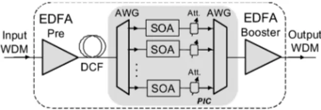
Fig. 1. Scheme of a WDM amplification site that includes the proposed WDM 2R regenerator block.
exploited to achieve the 2R regeneration of OOK signals, ei-ther RZ and NRZ. This is obtained by preventing the patterning effects. To this aim, in a saturated SOA the noisy signal should co-propagate together with its inverted copy at a different wave-length: the resulting signal, being almost at constant intensity, does not induce gain-related intensity distortions, but still takes advantage from the hard limiting effect of the SOA on the noise [7], [8].
We extend here this principle to signals having alternative modulation formats and constant envelope (CE). In this case a single saturated SOA (with no additional logically inverted copy) could provide direct noise compression. If this approach were successful, we could use it to regenerate wavelength divi-sion multiplexed (WDM) signals. This could be accomplished by using an optical circuit made of an array of SOAs and a couple of AWGs, as we show in Fig. 1. The circuit would in-clude a pre-amplification stage in an Erbium Doped Fiber Am-plifier (EDFA). Likely a dispersion compensating fiber should also be included, in order to recover the CE property, which is usually lost because of fiber chromatic dispersion [9]. The op-tical amplifier should move the opop-tical power of each channel up to a level that produces substantial saturation in any SOA. The second AWG would multiplex together all the channels, which could be eventually re-amplified by another EDFA. Moreover, an array of optical attenuator after the SOAs could be used, in case, for channel by channel power equalization. This solution involves only established building blocks, and it could be im-plemented by using current Indium Phosphate technology, in a small-form photonic integrated circuit (PIC) [10], [11].
In this paper, we experimentally demonstrate that the above limiting amplification works properly at 40 Gb/s in case of two CE modulation formats, namely polarization shift keying (PolSK) and frequency shift keying (FSK), when they are received by direct detection, whilst it suffers from limitations if applied on DPSK signals. The paper is organized as follows. In Section II, we report the 2R results for 40 Gb/s PolSK. In Section III, we first describe the generation of a 40 Gb/s FSK signal and then the reshaping results obtained for this signal. In Section IV, we study the case of 40 Gb/s Differential Phase
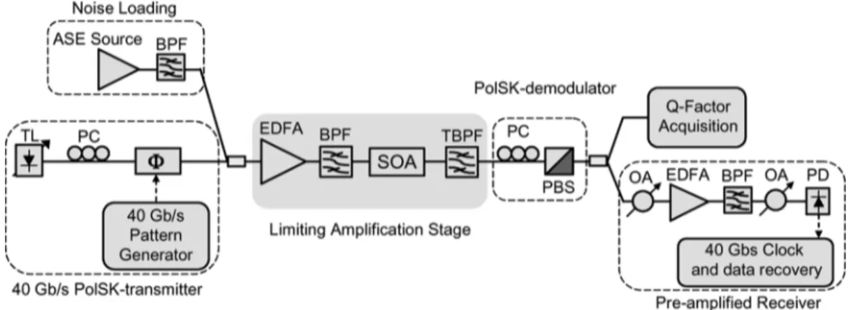
Fig. 2. Experimental setup for the PolSK 2R regenerator. TL: Tunable Laser, PC: Polarization Controller, 8: Phase Modulator, BPF: BandPass Filter, EDFA: Erbium Doped Fiber Amplifier, TBPF: Tunable BandPass PBS: Polarization Beam Splitter, OA: Optical Attenuator, PD: Photodiode.
Shift Keying (DPSK). In this last case the signal is received by using a 1-bit delay interferometers and we found relevant limitations of the AOR scheme, which are clearly related to the phase-intensity coupling in the semiconductor amplifier.
II. 40 GB/SPOLSK—2R EXPERIMENTALRESULTS
We report in Fig. 2 the experimental setup for the PolSK AOR. We generated a 40 Gb/s PolSK signal by using a tune-able laser (at 1555.4 nm) whose output lightwave is rotated and injected at in respect of the axes of a LiNbO phase mod-ulator driven by a long Pseudo Random Bit Sequence (PRBS) [12]. The signal was combined with ASE noise (from an EDFA source); in order to emulate the effect of the input AWG in Fig. 1, an optical bandpass filter (BPF), centred at the signal wavelength, filtered the ASE noise. The limiting ampli-fication stage, which is common to all the experiments, was re-alized using an EDFA, another BPF, an high gain SOA and a flat-top optical filter: this filter that is tuneable both in wave-length and in bandwidth and it was used to remove the excess noise from the SOA.
The SOA was a multi-quantum-well device with around 30 dB gain, 13 dBm output saturation power and 17 ps gain re-covery time when biased at 300 mA. The saturated polarization dependent gain was less than 1 dB. The input power to the SOA was around 7 dBm corresponding to 24 dB gain compression.
Signal demodulation was obtained by using a manually controlled polarization controller (PC) and a polarization beam splitter (PBS, 23 dB polarization contrast ratio), as in [12]. The signal was thus detected by means of a pre-amplified receiver (an EDFA followed by a 2 nm bandpass filter and a PIN pho-todiode having 36 GHz bandwidth). A sampling oscilloscope equipped with a 53 GHz optical head was also used for eye diagram acquisition and -factor estimation.
We show in Fig. 3 the input and output optical spectra of the PolSK signal, where we can appreciate that there is no apparent distortion. On the other hand, in the time domain, significant re-shaping was observed. Thanks to the CE property of the PolSK signal, the limiting amplification in the SOA did not affect the waveform yet it does provide noise compression. The SOA ef-fect on the noisy signal can be viewed as an optical high pass
Fig. 3. 40 Gb/s PolSK input and output spectra from the reshaping stage.
filter with a frequency cut-off given by the inverse of the re-covery time (more than 50 GHz in this case) and noise intensity reduction factor related to the amount of gain saturation [5].
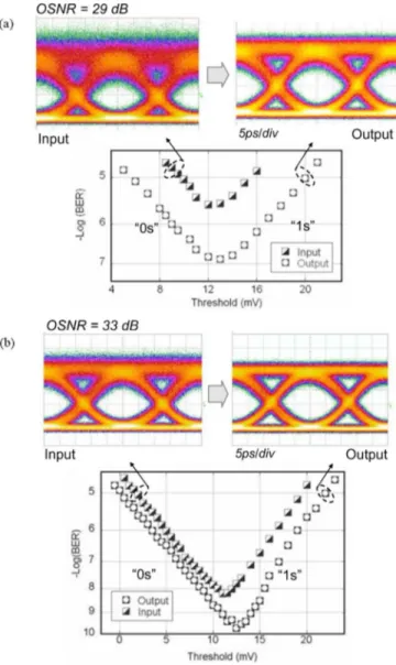
As examples, in Fig. 4 we report the input and output eye di-agrams for two cases in which the input optical signal-to-noise ratio (OSNR) was set to 29 Fig. 4(a) and 33 dB Fig. 4(b). OSNR was measured on 0.1 nm bandwidth. To avoid possible spurious effects and unfair comparison, eye diagrams and -factor com-parisons are made after filtering the signal (either the input or output) with the same flat-top tuneable optical filter. We see a clear eye-opening. In the same figures (lower insets), we report the corresponding BER versus threshold diagrams, which pro-vide a direct measurement of the reshaping effect on the signal probability density function (pdf): an apparent compression is found for both logical symbols. This also gives an improve-ment of the overall BER value, which even if is theoretically unexpected [13], is here possible because the 40 Gb/s receiver was not ideal both in terms of optical and electrical filtering bandwidth.
It is worth noting that this scheme always produces noise compression on both logical “one” and “zero” levels. Indeed, PolSK signal exploits two orthogonal polarization states and has constant intensity, thus the amplifier compresses the intensity noise on both polarizations, without mixing the two tion states. The PBS demodulator actually selects one polariza-tion state so that the “ones” level is clearly compressed while the “zeros” level is mainly determined by the PBS contrast ratio.
Fig. 4. Input and output eye diagrams from the reshaping stage with the cor-respondent BER versus Threshold measurements for the cases (a) 29 dB and (b) 33 dB input OSNR (on 0.1 nm).
However power fluctuations are attenuated also on the “zeros” even though the amount of noise reduction that can be appreci-ated depends on the PBS contrast ratio, i.e., the highest is the contrast ratio, the lower is the “zeros” level power and the noise compression that can be observed.
In order to investigate the AOR for various noise input levels, we used the signal-to-noise ratio function implemented in the sampling oscilloscope [14]. This function as the same definition as the -factor, is the ratio of the signal difference between one level and zero level relative to the noise present on both levels. This parameter is thus similar to factor, but, the noise levels contributed by the instrument cannot be removed, therefore it provides a slightly pessimistic -factor measurement [14]. In the following we will refer to -factor measurement when using this function.
The -factor would be a valid parameter for describing the signal quality if the effect of ASE noise could be approximated as a Gaussian additive noise. Indeed in this case there is a direct correspondence with the BER value of the signal. Although this is the case for the input signal that is loaded with ASE noise,
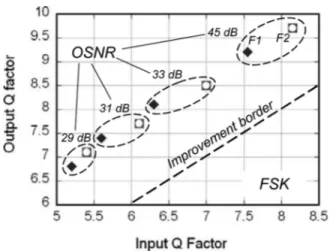
Fig. 5. Input-OutputQ-factor evolution for the 40 Gb/s PolSK signal at varying the OSNR (measured on 0.1 nm).
after the nonlinear reshaping in the SOA, the signal pdfs are no longer Gaussian. Hence, here the -factor looses its direct relation with the signal BER. However, it is still a significant figure of merit of the signal eye opening so that we use here the input-output -factor evolution for a quantitative evaluation of the signal reshaping. The results are reported in Fig. 5. We found a sound -factor improvement by around 2 dB for input signals with OSNR values ranging from 29 to 33 dB. Around 1 dB was found for a cleaner signal with 45 dB input OSNR. As an example, the eye opening of the diagrams reported in Fig. 4 dB corresponds to around 1.9 dB -factor improvement.
When working with optimal receivers, AOR’s can only op-erate a noise redistribution which corresponds to an eye-diagram opening and prevent occurrence of errors in successive trans-mission trunks; however AOR’s can neither correct errors nor improving the BER. Practically, this poses a lower bound on the quality of signals that can be processed by an AOR. We thus selected an input -factor range (from 4.5 to 8.6) that matches typical signal degradation levels occurring in practical systems at all-optical regeneration sites. As can be seen from Fig. 4(a), the 4.5 input -factor corresponds to a poor BER that gives a quite close eye diagram. In addition, the re-circulating loop experiment performed exploiting a similar hard limiting ef-fect in SOAs [15] guarantees that noise accumulation and also higher noise levels do not limit in principle the present scheme. On the other hand, 8.6 -factor corresponds to a very low BER and this measurement guarantees that the scheme works prop-erly without adding any significant distortion or nonlinear noise also in case of low noise signals.
III. 40 GB/SFSK—2R EXPERIMENTALRESULTS
FSK is another promising CE modulation format, because it could be generated by direct modulation of the semiconductor lasers [16], [17] and can have large tolerance to nonlinear trans-mission effects [18]. Furthermore, FSK can also be simply de-modulated by optical filtering [19], [20] and thus received by direct (or balanced) detection.
As today a direct modulated FSK signal is not yet possible at 40 Gb/s, our FSK transmitter used the scheme proposed in [20], and shown in Fig. 6. We used two lasers, emitting at the
Fig. 7. Optical spectrum of the FSK signal with the eye diagrams of the two sig-nals at the two carriers. In the lower part the overall FSK waveform is reported.
frequencies F1 and F2, both around 1555 nm and separated by 0.6 nm.
The two output lightwaves entered a LiNbO phase modu-lator with a linear polarization state at in respect of the principal axes. We thus obtained two orthogonal PolSK signals, with inverted bit sequence, which were then converted into two intensity modulated NRZ thanks to a properly set PC and a PBS [20]. Because of the PBS these two signals have the same state of polarization, are inverted in logic and actually are the two components of a 40 Gb/s FSK signal. The resulting FSK signal has an overall constant intensity profile (see Fig. 7), thus it could effectively exploit the SOA-based AOR. In [20] the authors re-ported at 10 Gb/s that 5 times the bit-rate wavelength-separa-tion was required to avoid any sensitivity penalty in respect to usual NRZ. Here we found that, thanks to the high rejection ratio 40 dB flat-top filter we used for demodulation, a wavelength spacing of only 1.9 times the bit-rate was possible. However FSK signals generated by direct laser modulation or by using an external modulator can have more compact spectra [16], [19], [21]. We expect that using CE FSK signals generated with dif-ferent transmitters cannot affect our results.
At the receiver end, we used the tuneable flat-top filter (band-width set to 0.55 nm) as demodulator before the direct-detec-tion. Thanks to the CE, the limiting amplification in the SOA (input power around 7 dBm) worked also in this case, effec-tively compressing the noise levels on the FSK signal. We could observe both the corresponding F1 and F2 signals by tuning
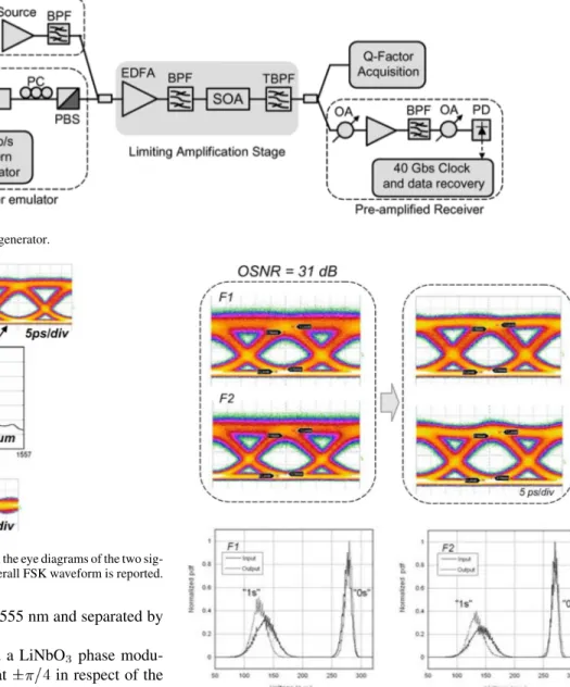
Fig. 8. In the upper part, input and output eye diagrams from the limiting stage. The two waveforms correspond to the two carriers F1 and F2 composing the FSK signal selected by the bandpass filter. In the lower part, the corresponding probability density functions (pdfs).
the flat-top filter. We could therefore assess the reshaping ef-fectiveness by measuring the input-output -factor evolution at F1 and F2. Unfortunately, our FSK transmitter had limited po-larization stability, which was not enough to allow for reliable and repeatable BER measurements (the BER versus threshold measurements required minutes for each run and the slight po-larization changes occurring during the BER measurement did not allowed to obtain many accurate BER values). Therefore, we could only gather information on the signal pdfs from the recorded eye diagrams. For the pdf extrapolation we used a 5 ps sampling window centred at the optimal sampling time. As an example of the results, we report in the upper part of Fig. 8 the input and output eye diagrams for F1 and F2, obtained for 29 dB input OSNR. We found a clear eye opening corresponding to around 1.5 dB -factor improvement. In the lower part of the figure we report the corresponding normalized pdfs and we see that the noise squeezing is more effective on the noisier “ones”
Fig. 9. Input-OutputQ-factor evolution for the 40 Gb/s FSK signal at varying the OSNR. The two points for every OSNR value account for the two waveforms at frequencies F1 and F2 composing the FSK.
level than on the “zeros” level. Differently from the previous PolSK case here the “zeros” level is mostly unaffected. This is probably due to the particular FSK transmitter implementation we used for this experiment and, moreover, as we see in the fol-lowing, some spurious four wave mixing could be responsible for adding nonlinear noise on the signal.
In Fig. 9 we report all the input-output results taken, as in the previous case, for OSNR values ranging from 29 to 45 dB. In all cases we found a net improvement of the factor. The slight imbalance between the F1 and F2 values was due to the FSK transmitter. Indeed, as we can observe in the spectrum of Fig. 7, the phase modulator introduces a different chirp on the two carriers so that the two components of the FSK signal have a different shape and a slightly different -factor value. How-ever, in all cases we obtained an almost constant -factor im-provement (around 1.5 dB). In Fig. 10 we report the input and output spectra: here we can see some small four wave mixing (FWM) lightwaves (at around dB), produced by the in-teraction between the two signals in the SOA. This inin-teraction arises here as in this practical FSK implementation the two sig-nals have some small (yet non zero) temporal superposition at the bit transition edges due to the finite bandwidth and the lim-ited extinction ratio of the modulator. This effect could slightly reduce the effectiveness of the reshaping process adding some spurious in-band beating-noise. This is expected to be more ap-parent on the less noisy “zeros” level. However this effect is not expected for FSK signals generated by direct laser modu-lation or by external modulators. In that case the FSK is not made by two partially time-overlapping signals and when doing filter-based demodulation and direct detection, the “zeros” level is determined by the filter extinction ratio. Indeed, noise reduc-tion is expected to be effective in a way similar to the previous PolSK case.
IV. LIMITINGAMPLIFICATION OFDPSK
Finally we tested the limiting circuit with a 40 Gb/s NRZ-DPSK signal. The experimental setup is reported in Fig. 11. We used a Mach–Zehnder modulator biased at null and driven by a long PRBS to produce the DPSK signal. Therefore, the
Fig. 10. 40 Gb/s FSK input and output spectra from the reshaping stage.
signal was not exactly CE, but showed the well-known deeps at the phase transitions. In order to reduce the signal distortions related to those deeps waveform we lowered the signal power at the power SOA input down to 4 dBm and the current to 190 mA. The demodulation was made by using a 1 bit delay interfer-ometer. As an example input-output eye diagrams for 31 dB input OSNR are reported in Fig. 12. In this case, although the limiting amplification reduces the noise on the “ones”, we found a net noise increase on the “zeros”. This is due to the Kramers–Kronig like relation between gain and refractive index in the SOA [22]. Indeed, gain fluctuations caused by the intensity noise are translated in refractive index fluctuations, which eventually affect the phase of the signal [23]. This effect is currently expressed by [24]
(1) where is the phase shift caused by the gain temporal fluctuations and is the line-width enhancement factor or Henry factor of the amplifier. The time-dependent gain value is determined by the input intensity and by the gain satura-tion. Random intensity changes at the input, e.g., due to ASE noise, modulate the gain, thus producing random phase fluctua-tions (i.e., nonlinear phase noise). Such fluctuafluctua-tions add to both “ones” and “zeros” symbols thus reducing the effectiveness of the reshaping as we see in Fig. 12. The overall result is that for any input OSNR value the nonlinear noise transfer process limits the -factor improvement so that input and output values are always quite close, as we see in Fig. 13. Here we report the -factor for various input OSNR values (from 29 to 45 dB). For the noisier signals with 29 and 31 dB OSNR the strong noise re-duction on the “ones” level gives some limited signal improve-ment. For the signals with higher OSNR (33 and 45 dB) the nonlinear noise transfer prevails and makes the output -value even worst than it was at the input.
However, we still see that the limiting amplification properly works with the intensity noise. As the nonlinear phase noise transfer is mainly determined by the parameter of the SOA, it is possible to obtain a certain signal improvement by carefully choosing the input power and the SOA current (or by using SOAs with low ) [25]. Clearly the signal reshaping will be
Fig. 11. Experimental setup for the DPSK limiting amplification. IM: Intensity Modulator, MZDI: 1-bit delay Mach–Zehnder Delay Interferometer.
Fig. 12. Input and output 40 Gb/s DPSK eye diagrams for 31 dB OSNR. The noise transfer from intensity on ones symbols to phase on both symbols in the SOA is highlighted.
Fig. 13. Input-OutputQ-factor evolution for the 40 Gb/s DPSK signal at varying the OSNR.
limited by the nonlinear noise hence, it will be in any case lower than for the previous cases.
Finally, we note that the DPSK format is known to be quite affected by the nonlinear phase noise due to SOA gain varia-tions, when the SOA is used as booster [26] or in-line amplifier. However, also in the last case, a comparative study [9] showed that this format is by far more affected than PolSK, because of the modulation type and the interferometric detection. This fur-ther supports our conclusion that the proposed AOR can reshape the PolSK and the FSK formats much better than DPSK.
V. CONCLUSION
We proposed and experimentally demonstrated a simple scheme for 2R all-optical regeneration of 40 Gb/s signals
having CE modulation formats. For the first time, to the best of our knowledge, we obtained reshaping of PolSK and FSK 40 Gb/s signals. We also studied the DPSK case and found that the phase-to-intensity coupling in the SOA strongly limits the application of the present scheme to this modulation format. We underline that, as it was recently demonstrated with re-circu-lating loop experiments [15], [27], we expect that this technique can be also effective when cascaded, i.e., to be resilient to noise accumulation in case of multiple SOA limiting amplification stages.
Finally, we note that this simple scheme may be extended to WDM systems, using a compact photonic integration circuit: as the AOR would be made out of common well-known existing blocks and would require not any interferometer structure, we expect that it would have no critical implementation or stability issue.
REFERENCES
[1] Z. Zuqing, M. Funabashi, P. Zhong, L. Paraschis, D. L. Harris, and S. J. B. Yoo, “High-Performance optical 3R regeneration for scalable fiber transmission system applications,” J. Lightw. Technol., vol. 25, no. 2, pp. 504–511, Feb. 2007.
[2] J.-C. Antona, M. Bortz, R. Dodd, J. Livas, P. Peloso, and A. Saleh, “Optical transmission evolution: From digital to analog to? network tradeoffs between optical transparency and reduced regeneration cost,”
J. Lightw. Technol., vol. 23, no. 1, pp. 219–224, Jan. 2005.
[3] C. Kouloumentas, P. Vorreau, L. Provost, P. Petropoulos, W. Freude, J. Leuthold, and I. Tomkos, “All-fiberized dispersion-managed multi-channel regeneration at 43 Gb/s,” IEEE Photon. Technol. Lett., vol. 20, no. 22, pp. 1854–1856, Nov. 2008.
[4] X. Yi, R. Yu, J. Kurumida, and S. J. B. Yoo, “Modulation-format-in-dependent wavelength conversion,” in Proc. OFC/NFOEC 2009, 2009, Paper PDPC8.
[5] G. Contestabile, R. Proietti, N. Calabretta, and E. Ciaramella, “Cross-Gain compression in semiconductor optical amplifiers,” J.
Lightw. Technol., vol. 25, no. 3, pp. 915–921, Mar. 2007.
[6] G. Contestabile, M. Presi, R. Proietti, and E. Ciaramella, “Optical re-shaping of 40-Gb/s NRZ and RZ signals without wavelength conver-sion,” IEEE Photon. Technol. Lett., vol. 20, no. 6, pp. 1133–1135, Jul. 2008.
[7] S.-J. Kim, J.-H. Han, J.-S. Lee, and C.-S. Park, “Intensity noise sup-pression in spectrum-sliced incoherent light communication systems using a gain-saturated semiconductor optical amplifier,” IEEE Photon.
Technol. Lett., vol. 11, no. 8, pp. 1042–1044, Aug. 1999.
[8] K. Sato and H. Toba, “Reduction of mode partition noise by using semi-conductor optical amplifiers,” IEEE J. Sel. Topics Quantum Electron., vol. 7, no. 2, pp. 328–333, Mar./Apr. 2001.
[9] E. Ciaramella, V. Donzella, and A. D’Errico, “Using semiconductor optical amplifiers with constant envelope WDM signals,” IEEE J.
[16] R. S. Vodhanel, A. F. Elrefaie, M. Z. Iqbal, R. E. Wagner, J. L. Gimlett, and S. Tsuji, “Performance of directly modulated DFB lasers in 10-Gb/s ASK, FSK, and DPSK lightwave systems,” J. Lightw.
Technol., vol. 8, no. 9, pp. 1379–1386, Sep. 1990.
[17] A. Klekamp, W. Idler, and R. Dischler, “Comparison of FSK by di-rectly modulated laser with DPSK, NRZ and RZ modulation formats at 10 Gb/s,” in Proc. ECOC 2003, p. 118, paper We4.
[18] N. Chi and S. Yu, “Transmission properties of a 40 Gb/s signal in FSK modulation format,” in Proc. ECOC 2005, 2005, vol. 3, pp. 729–730. [19] T. Kawanishi, K. Higuma, T. Fujita, J. Ichikawa, S. Shinada, T.
Sakamoto, and M. Izutsu, “10 Gbit/s FSK transmission over 95 km SMF using an external optical FSK modulator,” in LEOS 2004., 2004, vol. 2, pp. 609–610.
[20] S.-S. Pun, C.-K. Chan, and L.-K. Chen, “A novel optical fre-quency-shift-keying transmitter based on polarization modulation,”
IEEE Photon. Technol. Lett., vol. 17, no. 7, pp. 1528–1530, Jul. 2005.
[21] T. Kawanishi, K. Higuma, T. Fujita, S. Mori, S. Oikawa, J. Ichikawa, T. Sakamoto, and M. Izutsu, “40 Gbit/s versatileLinbo lightwave modulator,” in Proc. ECOC 2005, 2005, vol. 4, pp. 855–856. [22] K. A. Shore and D. A. S. Chan, “Kramers-Kronig relations for
non-linear optics,” Electron. Lett., vol. 26, pp. 1206–1207, 1990. [23] X. Wei and L. Zhang, “Analysis of the phase noise in saturated SOAs
for DPSK applications,” IEEE J. Quantum Electron., vol. 41, no. 4, pp. 554–561, Apr. 2005.
[24] G. P. Agrawal and N. A. Olsson, “Self-phase modulation and spectral broadening of optical pulses in semiconductor laser amplifiers,” IEEE
J. Quantum Electron., vol. 25, no. 11, pp. 2297–2306, Nov. 1989.
[25] P. Johannisson, G. Adolfsson, and M. Karlsson, “Suppression of phase error in differential phase-shift keying data by amplitude regeneration,”
Opt. Lett., vol. 31, pp. 1385–1387, 2006.
[26] X. Wei, Y. Su, X. Liu, J. Leuthold, and S. Chandrasekhar, “10-Gb/s RZ-DPSK transmitter using a saturated SOA as a power booster and limiting amplifier,” IEEE Photon. Technol. Lett., vol. 16, no. 6, pp. 1582–1584, Jun. 2004.
[27] A. D’Errico, G. Contestabile, R. Proietti, M. Presi, E. Ciaramella, L. Bramerie, M. Gay, S. Lobo, M. Joindot, J. C. Simon, D. Massoubre, H. T. Nguyen, and J.-L. Oudar, “2R optical regeneration combining XGC in a SOA and a saturable absorber,” in Proc. OFC/NFOEC 2008, 2008, Paper OWK4.
Dr. Contestabile is one of the reviewers of the IEEE/OSA JOURNAL OF
LIGHTWAVE TECHNOLOGY, IEEE PHOTONICSTECHNOLOGY LETTERS, IEEE JOURNAL OF QUANTUMELECTRONICS, Optics Express, Optics Letters, and
Optics Communications.
Marco Presi received the Laurea degree in physics from “La Sapienza”
Univer-sity of Rome in 2001 and the Ph.D. degree in applied physics at the UniverUniver-sity of Pisa, Pisa, Italy, in 2006.
Since 2007, he has been a Research Associate at Scuola Superiore Sant’Anna, Pisa, Italy, where he currently works on WDM optical systems. He coauthored more than 50 papers published in international peer-reviewed journals and in international conferences.
Ernesto Ciaramella (M’06) was born in Rome, Italy,
in 1967. He received the Laurea degree (cum laude) from the “La Sapienza University,” Rome, in 1991.
In 1992, he received a scholarship from Alcatel. During 1992–1994, he was a Researcher with the “Fondazione Ugo Bordoni,” where he was engaged in research on nonlinear optical effects. During 1994–1998, he was with the Centro Studi e Lab-oratorie Telecommunicazioni S.p.A., Turin, Italy. During 1998–2000, he was a Scientific Researcher with the “Fondazione Ugo Bordoni,” where he was engaged in research on optical transmission systems and network architectures. During 2001–2002, he was a Research Manager at the Consorzio Nazionale In-teruniversitario per le Telecomunicazioni (CNIT) National Photonic Networks Laboratory, Pisa, Italy. Since 2002, he has been an Associate Professor with the Scuola Superiore Sant’Anna, Pisa. His research activity covers various issues in optical communications (components, systems, networks). He participated into various European research projects (OPEN, PHOTOS, ATLAS, NOBEL). He published approximately 130 papers and he is author/coauthor of ten inter-national patents. Presently, he is leading a research group working on optical transmission systems and optical processing. His main research interests are: WDM systems, alternative modulation formats, 40 Gbit/s systems, all optical clock recovery, optical regeneration, WDM PON architectures, radio-over fiber systems and free space optic communications.
Dr. Ciaramella served/is serving in the Technical Program Committees (TPC) of the Optical Fiber Communication Conference (OFC 2007–2010), and of the European Conference of Optical Communications (ECOC 2007–2008).