Journal of Instrumentation
OPEN ACCESS
A study of asymmetric tensile properties of large area GEM foil
To cite this article: G. Saviano et al 2020 JINST 15 P090112020 JINST 15 P09011
Published by IOP Publishing for Sissa MedialabReceived: June 25, 2019 Revised: January 24, 2020 Accepted: June 29, 2020 Published: September 8, 2020
A study of asymmetric tensile properties of large area
GEM foil
G. Saviano,a,b S. Muhammad,c,1L. Benussi,aS. Bianco,aD. Piccolo,aM.A. Caponero,a,d L. Passamonti,aD. Pierluigi,aA. Russo,aM.G. Santonicola,bY.M. Chin,eA. Sharma,f S.A.E. Langeslag,f S. Sgobba,f I.A. Santillanaf and C. Vendittozzig
aLaboratori Nazionali di Frascati — INFN, Frascati,
via E. Fermi 40, 00044, Frascati, Rome, Italy
bUniversity of Rome “La Sapienza” — Department of Chemical Engineering Materials Environment and
UdR INSTM, Rome,
via Eudossiana 18, 00184 Rome, Italy
cExperimental High Energy Physics Department (EHEP), National Centre for Physics (NCP),
QAU Campus, Shahdra Valley Road, Islamabad — 44000, Pakistan
dCentro Ricerche ENEA Frascati,
via E. Fermi 45, 00044 Frascati, Rome, Italy
eCentre for Frontier Materials Research, School of Materials Engineering, Universiti Malaysia Perlis,
02600 Arau, Perlis, Malaysia
fCERN, European Organisation for Nuclear Research,
385 Route de Meyrin, Geneva, Switzerland
gFaculdade do Gama (FGA), Universidade de Brasília (UnB),
Área Especial, Projeção A, UnB Setor Leste Gama, Brasília DF, 72444-240, Brazil
E-mail: [email protected]
Abstract: Gas Electron Multiplier (GEM) technology is being used in various applications, par-ticularly in high energy physics experiments. The GEM is known as a reliable detector in high radiation environment which can maintain high temporal and position resolution. GEM foil is the basic part of the detector which consists of a composite material (polyimide and copper). Large size GEM foil has complex mechanical structure and asymmetries which mainly arises due to formation of the HV sectors in the foil. These asymmetries become very relevant when large size foils are stretched to build a detector. In this article asymmetry affects are presented that define the tensile properties of a large size segmented GEM foil.
Keywords: Gaseous detectors; Materials for gaseous detectors; Detector design and construction technologies and materials; Manufacturing
1Corresponding author.
c
2020 CERN. Published by IOP Publishing Ltd on behalf of Sissa Medialab. Original content from this work may be used under the terms of theCreative Commons Attribution 4.0 licence. Any further distribution of this work must maintain attribution to the author(s) and the title of the work, journal citation and DOI.
2020 JINST 15 P09011
Contents1 Introduction 1
2 Asymmetry in the large size GEM foil 1
3 Samples preparation 2
4 Measurements scope and procedure 2
5 Results and discussion 3
6 Conclusion 8
1 Introduction
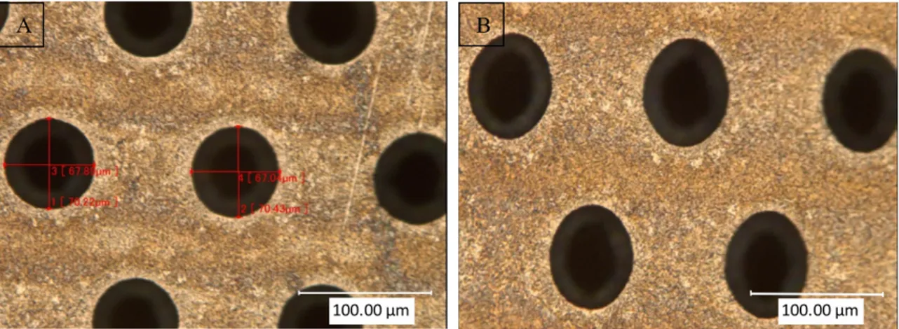
A GEM foil [1] is the basic component of the GEM detector, the foil consists of a 50 µm thick polyimide coated with 5 µm thin copper on both sides and perforated with high density micro-holes (about 70 holes/mm2), as shown in figure1. Intense electric field in the GEM foil holes is the
source of charge amplification in the detector. The GEM technology is proven to work well in high radiation conditions, and it has an excellent resistance against the radiation degradation which could happen in the gaseous detector [2].
The GEM detectors have been recently [3–7] employed as large area muon detectors at high intensity hadron colliders. Each GEM detector contains three identical GEM foils [5]. The GEM foil studied in this paper is trapezoidal [8] in shape and has an area of about 0.409 m2. The foil is divided into small HV sectors to avoid accumulation of large amounts of static charge. GEM foil asymmetry and its effects on the tensile and hole deformation are presented in this article.
2 Asymmetry in the large size GEM foil
Various types of asymmetries exist in the GEM foil with respect to its mechanical design. The first type of asymmetry is due to formation of the HV sectors partition. Approximately 1 mm HV Partition (HVP) lines generate three different scenarios, i.e., (i) one side of the HVP lines have no copper coating; (ii) the other side is copper coated with same thickness as rest of the foil (iii) the HVP lines have no holes. The second asymmetry arises due to unequal distance among the HVP lines. The unequal distance arises to keep the uniform area of the each HV sector, which is about 100 cm2in the trapezoidal shape of the GEM foil [5]. Double mask technique could be adopted for small size GEM foil fabrication but for large size it is difficult to handle the alignment of the both sides’ holes. The GEM foil used in this study is fabricated by single mask technique to overcome the mask misalignment problem which could be observed in case of double mask technique [9].
2020 JINST 15 P09011
Figure 1. The GEM foil holes shape under the microscope, (A). After loading the sample in the machine
without applying any stress ~ 0MPa, (B). the sample is under stress ~ 86.3 MPa, the holes deformation is significant.
The new assembly technique for the large size GEM detector, the foils are stretched to maintain the uniform gaps among three GEM foils, drift and readout boards. The foils stretching technique to assemble the detector, helps to maintain the maximum active area of the detector because no glue and spacers are used inside the detector. This assembly technique is relatively simple and fast [2,10,11].
3 Samples preparation
In table1, the samples are listed which are used in this study. Total 27 samples are used in the tests. Each sample has thickness of 0.060 mm, width of 20 mm and length more than 100 mm. However, during testing the gauge length is always kept precisely at 100 mm. The samples are cut in transverse and longitudinal directions. The transverse samples are without HVP lines and longitudinal samples with HVP lines. The longitudinal cut samples are taken from different regions of the foil, with fixed length but different numbers of the HVP lines. At certain length, the number of the HVP lines increase by going from narrow to wider side of the foil. In figure 1 (A), the holes pattern is shown after loading the sample in the machine before applying the stress ~ 0 MPa, and figure1(B) shows the holes deformation after applying stress ~86.3 MPa at the sample.
4 Measurements scope and procedure
This study is an extension of the previous work on tensile properties of GEM foils in harsh radiation and environmental conditions [12, 13]. For asymmetry study, two types of tests are performed, namely (i) holes deformation and (ii) tensile tests.
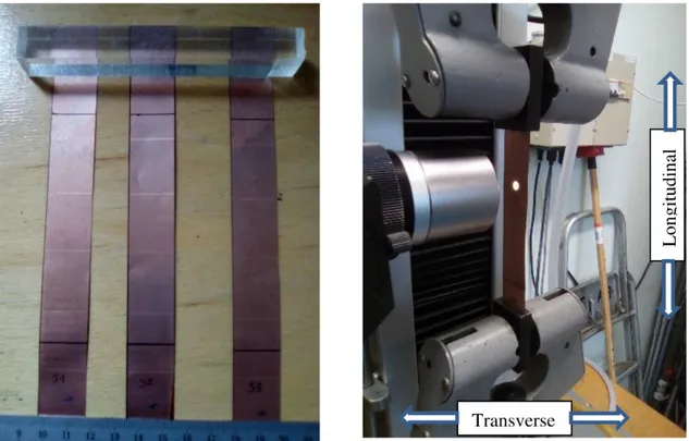
Tensile measurements are performed by using a Zwick/Roell Z010 displacement control ma-chine and following ASTM D882-02 standard [14], the test setup is shown in figure2. Samples are loaded singularly in the measuring device by keeping the gauge length, the length of a sample between two grips of the machine, at 100 mm and the cross head speed 5 mm/min. All tests are performed at constant temperature (25◦C ± 1◦C) and relative humidity (56 ± 2%). Two kinds of measurements are recorded for asymmetric studies such as; stress vs strain and stress vs holes
2020 JINST 15 P09011
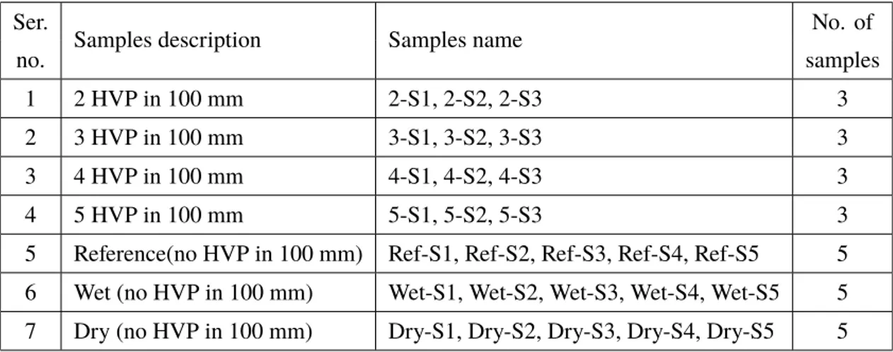
Table 1. Samples used for the study.
Ser.
Samples description Samples name No. of
no. samples
1 2 HVP in 100 mm 2-S1, 2-S2, 2-S3 3
2 3 HVP in 100 mm 3-S1, 3-S2, 3-S3 3
3 4 HVP in 100 mm 4-S1, 4-S2, 4-S3 3
4 5 HVP in 100 mm 5-S1, 5-S2, 5-S3 3
5 Reference(no HVP in 100 mm) Ref-S1, Ref-S2, Ref-S3, Ref-S4, Ref-S5 5
6 Wet (no HVP in 100 mm) Wet-S1, Wet-S2, Wet-S3, Wet-S4, Wet-S5 5
7 Dry (no HVP in 100 mm) Dry-S1, Dry-S2, Dry-S3, Dry-S4, Dry-S5 5
diameter variation. A high-resolution Keyence VHX-1000 digital microscope [15] is used to record micro size holes shape variation due to continuously increasing stress. By increasing stress, the changing of the holes dimensions is recorded in video, and then by applying certain time stamp, the holes images are taken. In one image (frame) about 4–5 complete holes fit in. These all measurements are performed at CERN- EN-MME department.
5 Results and discussion
As shown in table1, there are 3 to 5 samples in each set, one set of the samples is shown in figure2 (left side). The samples are stretched in the longitudinal direction, this is the direction of the applied stress on the sample and the transverse direction is perpendicular to the applied stress, as shown in figure 2 (right side). About 4–5 holes fit in one frame and only those holes are considered for analysis which fully fit inside the frame, partially fitted holes are discarded. An analysis is performed on the holes, to measure the deformation in the longitudinal and the transverse directions with respect to the applied stress.
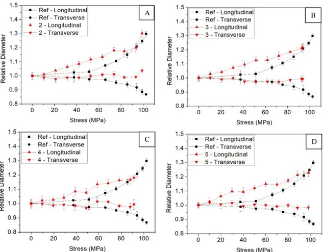
In figure 3, a comparison is shown of the holes deformation. Specifically, in figure3(A) the reference samples (i.e., without HVP lines) are compared with the two HVP lines samples. The deformation of the reference sample is small at lower stress (up to about 50 MPa) and increases exponentially for the higher stresses. The maximum holes relative deformation in longitudinal direction is 1.3 and in transverse direction the deformation is 0.86. Two HVP lines and reference samples have almost same maximum longitudinal holes deformation which is about 1.3. However, the maximum transverse deformation of the two-HVP lines is less than the reference samples.
In figure 3(B) the average values of holes deformations of the reference samples and three-HVP lines samples are compared. The overall deformation of the three-three-HVP lines samples is same as the two-HVP lines. The deformation onset in the longitudinal direction begins at lower stress than the transversal direction. The longitudinal maximum relative deformation of three-HVP lines is 1.21 and the transverse maximum relative deformation is 0.99 at 93.5 MPa. In figure 3(C) holes deformation average values of reference samples and four-HVP lines samples are compared. Longitudinal maximum deformation of four-HVP lines is 1.18 and in the transverse
2020 JINST 15 P09011
maximum deformation is 0.99 at 91.2 MPa. In figure 3(D) holes deformation average values ofreference samples and five-HVP lines samples are compared. Longitudinal maximum deformation of five-HVP lines samples is 1.22 and transverse maximum deformation is 0.98 at 98 MPa.
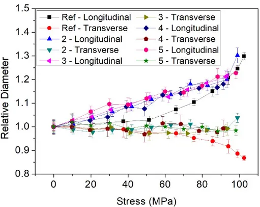
In figure4, mutual comparison is made among average references samples, two, three, four, and five-HVP lines. The samples which contain HVP lines follow the same way in general and overlap at most of the regions, differently from the reference samples, showing significantly different behavior.
Figure 2. (Left side). A set of samples contains four HVP lines, and (right side). A sample is loaded into the
Zwick/Roell Z010 displacement control machine and microscope is focused at a certain region of the sample.
In reference samples, the holes deformation in the transverse direction is relatively higher than the HVP lines samples, particularly after about 70 MPa. On the other hand, the longitudinal holes deformation is lower in the reference samples as compared to HVP lines in the stress range of about 15 MPa to 90 MPa. The mentioned different holes deformations in the reference samples and HVP lines samples at certain applied stress is due to the different ways of stress distribution on the samples with HVP lines and without HVP lines. The HVP lines region resist more to deform than the holes region. Therefore, the initial applied stress is translated first on the holes region which has less resistance to deform. A large part of a GEM foil is made of polyimide, which is a good absorber of water [16–18]. Therefore, it is very important to estimate the impact of moisture and dryness on the tensile and holes deformation of the GEM foil under constant increasing stress. In figure5, the humidity effects on the tensile and holes deformation of the foil are presented. Two sets of the reference samples are conditioned in two different ways, such as; one set is kept in 100% humidity for five days and the other set is kept in oven at 100◦C for 36 hours. These two sets are called wet and dry respectively. The holes deformation of wet and dry samples is compared with the reference samples set which are kept at room temperature.
2020 JINST 15 P09011
Figure 3. Hole deformation trends of the average of all the samples in each set are compared with respect
to the reference samples (without HVP lines) with different numbers of HVP lines samples such as (A) Two HVP lines, (B). Three HVP lines, (C). Four HVP lines, (D). Five HVP lines samples.
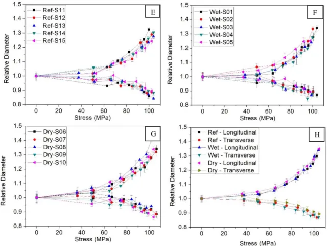
In figure5(E), (F) and (G) a comparison is made among the individual five samples of each type such as: reference, wet and dry samples respectively. Holes deformation in transverse and longitudinal direction for all the samples of each set follows almost same lines, this shows that there is no dimensional variation in the samples. An average comparison of these three sets of the samples is shown in figure5 (H). Generally, the average holes deformation trends seem uniform and there is not any significant effect due to moisture and dryness on the hole’s deformation.
In figure6(I), the reference samples tensile trends are compared with two, three, four and five HVP lines samples. Reference samples have significant difference in tensile trends than the samples which have HVP lines, e.g. at given stress the samples without HVP lines have higher strain than the HVP lines samples. In figure6(J), mutual comparison is made among the reference, dry and wet samples, all these samples have no HVP lines. Wet samples tensile trends are following very close path with respect to each other, but slightly lower than the reference and dry samples which is significant after 50 MPa. Reference and dry samples have almost same spreading in the tensile trends. It is observed, that at lower stress such as: from 8.3 MPa to 91.6 MPa , the holes deformation is fast in the longitudinal direction than the transverse direction for the HVP lines samples. Contrarily, the reference samples holes deformation rate is slower in the given stress range.
2020 JINST 15 P09011
Figure 4. Hole deformation mutual comparison is made among reference samples vs samples contain two,
three, four and five HVP lines.
There could be more than one reasons of the faster hole’s deformation in the HPV lines samples than the reference ones. However, the one reason could be that, in case of no HVP lines the applied stress is uniformly distributed at all the sample area. Because the sample material has the same strength everywhere but in case of HVP lines the region of HVP line as mentioned above, resists to deform instantly than the holes region. Therefore, the initial applied stress is directly translated on the hole’s region, where significant holes deformation could be seen at lower stress.
The different trends of the holes deformation in transverse and longitudinal direction are very important to understand that how the stress balance could be maintained to avoid the holes deformation during foil stretching in the GEM detector assembly.
Tensile tests show, that how the reference samples elongate more than the HVP lines samples at the same applied stress. Therefore, it is important to keep some margin in the transverse direction to compensate the extra elongation. GEM foil stretching in the transverse side will elongate higher, but holes deformation will be smaller at the certain range of the applied stress such as from 8.3 MPa to 66.7 MPa. However, after this stress the deformation in the transverse direction become faster. The holes deformation and tensile trends in the longitudinal and transverse direction of the GEM foil is not only because of one kind of asymmetry, but it is combination of all types of asymmetries as described above.
2020 JINST 15 P09011
Figure 5. Mutual comparison of the holes deformation of the each set of the samples (E). reference, (F).
wet, (G). dry and (H). average values of each set.
Figure 6. (I) Tensile test trends mutual comparison of reference (no HVP lines), two, three, four and five
HVP lines samples, (J). Tensile trends of no HVP line samples such as: reference, wet and dry.
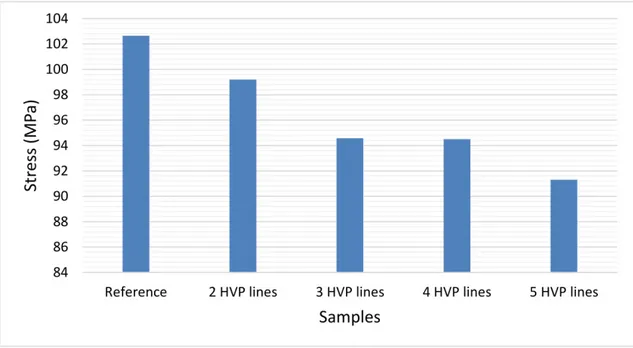
In figure7, a correlation is made among the different samples such as reference sample, 2 HVP, 3 HVP, 4 HVP and 5 HVP lines samples and Ultimate Tensile Stress (UTS) of each set. UTS is the maximumstressthat a material can withstand while being stretched before breaking. It could be seen
2020 JINST 15 P09011
Figure 7. Average Ultimate Tensile Stress (UTS) of the five sets of samples such as Reference, 2 HVP, 3
HVP, 4 HVP and 5 HVP lines.
that by increasing the numbers of HVP lines the UTS is decreases. Gradually decreasing of the UTS shows that HVP line region has lower strength than the holes region, the source of the lower strength in the HVP line is basically, due to the absence of the 5 µm copper coating at one side of the foil.
6 Conclusion
This study shows that how a large size GEM foil has several sources of asymmetries due to mechanical design. Two types of major asymmetries exist in the foil. The first asymmetry is due to the HV sectors partition lines, namely: (i) one side of the HVP lines have no copper coating; (ii) the other side is copper coated; and (iii) the HVP lines have no holes. The second asymmetry is due to unequal distance among the HVP lines.
The samples with HVP lines, the holes deformation is faster in longitudinal direction than the no HVP lines samples at the lower stress. The reason of this behavior is that, in case of the no HVP lines the applied stress is uniformly distributed at the entire sample. Because the sample material has the same strength everywhere but in case of HVP lines sample the region of the HVP line as mentioned earlier, it resists to deform immediately than the holes region. Therefore, the initial applied stress is directly transformed on the hole’s area, where significant holes deformation could be seen at the lower stress.
Holes deformation and tensile tests are performed on 27 samples. Significant differences in both hole deformation and tensile trends are observed due to asymmetries in the foil. The HVP lines reduce the foil material strength as shown in figure 7. This study suggests the importance, during detector assembly, of adequate balancing of tensile stress in the transvers and longitudinal directions. In order to avoid deformation of the holes that could eventually modify the electric field and the detector performance.
2020 JINST 15 P09011
AcknowledgmentsThe authors would like to thank Rui De Oliveira for providing the large size GEM foil, which is used in this study. Also thankful to CERN EN/MME department for allowing to use their lab facilities to perform the tests.
References
[1] F. Sauli, GEM: a new concept for electron amplification in gas detectors,Nucl. Instrum. Meth. A 386
(1997) 531.
[2] M. Hohlmann, C. Padilla, N. Tesch and M.P. Titov, Aging phenomena in gaseous detectors:
perspectives from the2001 workshop,Nucl. Instrum. Meth. A 494(2002) 179.
[3] A. Colaleo, A. Safonov, A. Sharma and M. Tytgat, CMS technical design report for the muon endcap
GEM upgrade, Tech. Rep.CERN-LHCC-2015-012, CERN, Geneva, Switzerland (2015)
[CMS-TDR-013].
[4] D. Abbaneo et al., Upgrade of the CMS muon system with triple-GEM detectors,2014 JINST 9 C10036.
[5] CMS Muon collaboration, Layout and assembly technique of the GEM chambers for the upgrade of
the CMS first muon endcap station,Nucl. Instrum. Meth. A 918(2019) 67[arXiv:1812.00411].
[6] CMS collaboration, The CMS experiment at the CERN LHC,2008 JINST 3 S08004.
[7] CMS collaboration, Technical proposal for the upgrade of the CMS detector through 2020, Tech. Rep.
CERN-LHCC-2011-006, CERN, Geneva, Switzerland (2011) [LHCC-P-004].
[8] G. Raffone, CMS trapezoidal GEM foil structural analysis,LNF-10/20(IR)note, Laboratori Nazionali di Frascati, Frascati, Italy, 20 September 2010.
[9] S.D. Pinto et al., Progress on large area GEMs,2009 JINST 4 P12009.
[10] D. Abbaneo et al., Performance of a large-area GEM detector prototype for the upgrade of the CMS
muon endcap system,IEEE Nucl. Sci. Symp. Med. Imag. Conf. Rec.(2014) 1.
[11] D. Abbaneo et al., GEM based detector for future upgrade of the CMS forward muon system,Nucl. Instrum. Meth. A 718(2013) 383.
[12] G. Saviano et al., A study of mechanical properties of foil materials for the GEM detector proposed
for the CMS muon system upgrade at LHC,Polymer Eng. Sci. 58(2017) 1539.
[13] L. Benussi et al., Gas electron multiplier foil holes: a study of mechanical and deformation effects,
2016 JINST 11 P08002.
[14] Standard test method for tensile properties of thin plastic sheeting, ASTM International Designation: D 882-02,https://www.astm.org/DATABASE.CART/HISTORICAL/D882-02.htm.
[15] Digital microscope — VHX-1000 series product webpage,
https://www.keyence.com/products/microscope/digital-microscope/vhx-1000/.
[16] D. Abbaneo et al., A study of film and foil materials for the GEM detector proposed for the CMS muon
system upgrade,2014 JINST 9 C04022.
[17] L. Benussi et al., Characterization of the water diffusion in GEM foil material,EPJ Web Conf. 174
(2018) 03005.
[18] G. Raffone, CHE and related stresses in GEM foils,INFN-13-11/LNFnote, Laboratori Nazionali di Frascati, Frascati, Italy, 2 July 2013.