UNIVERSITY cf CALABRIA
Faculty cf Engineering
Department of Mechanical Engineering
Ph. D. Thesis
XXIV Cycle (2008-2011)
Scuola di Dottorato "Pitagora" in Scienze Ingegneristiche
SSD: ING-IND/16 - Tecnologie e Sistemi di LavorazioneMechanisms and Modeling of White and Dark Layers
Formation in Hard Machining of AISI 52100 Steels
Coordinator
Supervisor
Candidate
Caruso
I~"'-~~
Dissertation Submitted to Obtain the Degree of Doctor in Mechanical Engineering
UNIVERSITÀ della CALABRIA
Facoltà di Ingegneria
Dipartimento di Meccanica
Dottorato di Ricerca in Ingegneria Meccanica
XXIV Ciclo (2008-2011)
Scuola di Dottorato "Pitagora" in Scienze Ingegneristiche
SSD: ING-IND/16 - Tecnologie e Sistemi di LavorazioneDissertazione finale sottomessa per il conseguimento il titolo di Dottore di Ricerca in Ingegneria Meccanica
Mechanisrns and Modeling ofWhite and Dark Layers
Formation in Hard Machining of AISI 52100 Steels
Coordinatore
e
or
Sergio Rizzuti-J
~ i~~
+r--
'4'
Candidato
Ing. Serafino Caruso
"
---'(.Y(~~
i
iii
T
ABLES OF
C
ONTENTS
C
HAPTERP
AGESI
NTRODUCTION……….….…... 1C
HAPTER
1
H
ARDT
URNINGP
ROCESS1.1
1.2
1.3
1.4
1.5
1.6
1.7
1.8
1.9
1.10
1.11
1.12
1.13
1.14
1.15
I
NDUSTRIALA
PPLICATIONS ANDL
IMITATIONS...
T
OOLW
EAR...
M
ETALLURGICALA
SPECTS...
C
UTTINGF
ORCES...
C
UTTINGT
EMPERATURES...
C
UTTINGM
ATERIALS...
M
ACHINET
OOL...
S
URFACEI
NTEGRITY...
A
CCURACY OF THEP
ROCESS...
C
OST...
R
ESIDUALS
TRESSESI
NFLUENCE...
F
INITEE
LEMENTM
ODELING...
M
OTIVATION OF THEP
RESENTW
ORK...
O
BJECTIVES ANDC
ONTRIBUTIONS...
O
RGANIZATION...
3
5
7
8
10
13
15
17
23
24
25
27
32
34
35
iv
C
HAPTER
2
W
HITEL
AYER INH
ARDM
ACHINING2.1
2.1.1
2.2
2.2.1
2.2.2
2.2.3
2.2.4
2.2.5
2.2.6
2.2.6.
A2.2.6.
B2.2.6.
C2.3
2.4
W
HITEL
AYERF
ORMATION...
E
FFECT OFM
ATERIALC
HARACTERISTICS ONW
HITEL
AYERF
ORMATION...
I
NFLUENCE OF THEC
UTTINGP
ARAMETERS...
I
NFLUENCE OF THEC
UTTINGS
PEED...
I
NFLUENCE OF THEF
EEDR
ATE...
I
NFLUENCE OF THEI
NITIALW
ORKPIECEH
ARDNESS...
I
NFLUENCE OF THET
OOLG
EOMETRY...
I
NFLUENCE OF THET
OOLM
ATERIAL...
I
NFLUENCE OF THEC
OOLINGC
ONDITIONS...
W
ETC
ONDITION...
M
INIMUMQ
UANTITYL
UBRICATION(MQL)
C
ONDITION...
C
RYOGENICC
OOLING...
I
NFLUENCE OF THEW
HITEL
AYER ONF
ATIGUEL
IFE...
S
UMMARY...
36
40
41
41
47
49
51
55
55
56
57
59
61
64
C
HAPTER
3
E
XPERIMENTALP
ROCEDURE FORI
NVESTIGATING THES
URFACEI
NTEGRITY3.1
3.2
3.3
3.4
3.5
3.6
E
XPERIMENTALP
ROCEDURE...
C
UTTINGT
OOLM
ATERIALP
ROPERTIES...
W
ORKPIECEM
ATERIALP
ROPERTIES...
E
XPERIMENTALS
ET-
U
P FORH
ARDM
ACHININGO
PERATIONC
UTTINGC
ONDITIONS...
E
XPERIMENTALS
ET-U
P FORM
ICROSTRUCTURALC
HANGESA
NALYSIS...
67
68
71
76
78
79
v
3.7
3.8
3.9
E
XPERIMENTALP
ROCEDURE ANDS
ET-U
P FORR
ESIDUALS
TRESSA
NALYSIS:
X-R
AYD
IFFRACTIONT
ECHNIQUE...
E
XPERIMENTALP
ROCEDURE ANDS
ET-U
P FORT
HERMALA
NALYSIS...
S
UMMARY...
83
91
93
C
HAPTER
4
E
XPERIMENTALR
ESULTS ANDA
NALYSIS4.1
4.2
4.3
4.4
4.5
4.6
4.7
4.7.1
4.7.2
4.7.3
4.7.4
4.7.5
4.8
C
UTTINGF
ORCES...
C
UTTINGT
EMPERATURES...
W
HITE ANDD
ARKL
AYERST
HICKNESS...
W
HITE ANDD
ARKL
AYERSH
ARDNESS...
W
HITE ANDD
ARKL
AYERSEDS
A
NALYSIS...
X-R
AYD
IFFRACTION FORP
HASEA
NALYSIS...
R
ESIDUALS
TRESSA
NALYSIS...
I
NFLUENCE OF THEC
UTTINGS
PEED...
I
NFLUENCE OF THEF
EEDR
ATE...
I
NFLUENCE OF THEI
NITIALW
ORKPIECEH
ARDNESS...
I
NFLUENCE OF THET
OOLG
EOMETRY...
I
NFLUENCE OF THEM
ICROSTRUCTURALC
HANGES(W
HITE ANDD
ARKL
AYERS)...
S
UMMARY...
96
99
102
108
112
115
123
125
126
127
128
128
130
vi
C
HAPTER
5
F
INITEE
LEMENTM
ODELING FORW
HITE ANDD
ARKL
AYERSF
ORMATION ANDR
ESIDUALS
TRESSESA
NALYSIS5.1
5.2
5.2.1
5.2.2
5.3
5.4
A
PPLICATION OFA
NALYTICAL ANDN
UMERICALA
PPROACHES FORP
REDICTING THEW
HITEL
AYER...
N
UMERICALM
ODELING...
A
DVANCEDE
MPIRICALM
ODELS FORP
REDICTINGW
HITE ANDD
ARKL
AYERSF
ORMATIONS...
P
ROPOSEDN
UMERICALP
ROCEDURE...
R
ESIDUALS
TRESSA
NALYSIS...
S
UMMARY...
133
134
135
142
144
146
C
HAPTER
6
N
UMERICAL ANDE
XPERIMENTALC
OMPARISON6.1
6.2
6.3
6.4
6.5
FE
C
ALIBRATION...
FE
V
ALIDATION...
FE
A
NALYSIS...
FE
R
ESIDUALS
TRESSP
REDICTION...
S
UMMARY...
148
157
165
167
171
C
ONCLUSION
...
A
CKNOWLEDGEMENT
...
R
EFERENCES
...
172
175
177
1
I
NTRODUCTION
ard turning, or turning of hardened steels (HRC > 45), is an attractive alternative to the other costly and yet environmentally harmful machining processes. Especially today, in which the economic crisis is interesting all over the world, hard turning is becoming more attractive for the good price/quality ratio. In fact, the potential process benefits as the higher process flexibility, the reduced setup time and the higher material removal rates are making hard turning the best choice in the surface finishing processes than grinding. However, the presence of the microstructural changes and their formation mechanisms, the influence of the cutting parameters and the tool geometry on the above mentioned microstructural changes and, lastly, the effects of these alterations on the surface integrity (roughness, residual stresses, etc.) have not been fully understood.
Although it is commonly believed that microstructual change (often called white layer) in hard turning is produced by thermally-induced phase transformation, there is limited understanding of the exact thermo-mechanical conditions present during its formation. Specifically, it is well known that white layer is the result of the combination of thermal effect (rapid heating and quenching which result in phase transformation) and mechanical effect (severe plastic deformation) but it is not well studied if thermal or mechanical effect is the main dominant cause of the phase transformation during hard machining.
For these lacks in scientific knowledge on microstructural phase transformations during hard turning, a wide experimental campaign was carried out with the aim to study and determine the influence of cutting tool geometry (honed and chamfered edges)
2
and process parameters (feed rate, cutting speed and workpiece initial hardness) on the machined surface in terms of residual stresses, microhardness modification, white and dark layers formation, etc.
Also, it was possible to investigate the metallurgical causes of the microstructural alterations. In particular, by EDS and X-Ray Diffraction analysis of the machined surface it was showed that white layer formation results in a martensitic structure, with the presence of retained austenite, for the phase transformation during hard turning. In addition, measurements of workpiece surface temperatures by thermo-camera suggest that phase transformations occur below the nominal austenite-start temperature due to high dislocation density associated with large strain.
Furthermore, no adequate numerical models are actually available in literature for predicting the phase transformations during turning of hardened steels. Therefore, a new FE strategy based on two advanced-empirical equations for white and dark layers prediction were developed and implemented by user subroutine in a commercial numerical software. Based on the comparison with experimental results it was verified the capability of the developed numerical strategy in predicting white and dark layers formation, hardness modification, cutting forces and temperatures, residual stress and the effect of white and dark layers on residual stress when orthogonal hard turning of AISI 52100 steel (54, 56.5 and 61 HRC) is carried out.
Finally, it is important to highlight that parts of the PhD activities were carried out in cooperation with research institutes in USA (Institute for Sustainable Manufacturing (ISM), University of Kentucky, Lexington, KY) and in Portugal (CEMDRX, laboratory for X-Ray Analysis of the Department of Physics of the University of Coimbra).
3
C
HAPTER
I
H
ARD
T
URNING
P
ROCESS
he aim of this chapter is to provide a general review on the several physical and thermo-mechanical aspects that characterize the hard turning processes. Metallurgical fundamentals, mechanism of chip formation, machine tool, cutting materials, cutting forces and stress distribution, energy, temperature, geometric accuracy and potential in hard machining are deeply discussed. A detailed description concerning the microstructural changes and phase transformations on the machined surface (affected layer) are also analyzed; furthermore, the influence of the residual stresses on the machined parts are reported. Finally, a consideration on the several Finite Element codes and their techniques, developed to simulate the hard turning processes, is showed.
1.1 – I
NDUSTRIALA
PPLICATIONS ANDL
IMITATIONSHard turning or cutting of hardened steel is performed on materials with hardness within the 45–68 Rockwell range using a variety of cutting inserts, preferably CBN. This is a topic of high interest for today's industrial production and scientific research [1-10]. Tests and first introductory steps have been made in automotive, gear, bearing, tool and die making industry. In research institutes and universities, basic
4
experimentally as well as theoretically investigations have been made since more than 25 years.
Mechanical components consisting of hardened steel are high performance components which are often loaded near their physical limits. Their functional behavior is principally influenced by the finishing processes which represent the last step in the process chain and are represented by cutting and grinding. For this reason finishing processes are defined as an important step and their results have to satisfy customer high quality requirements.
The product specific issues and demands also meet general trends in cutting such as flexibility, ecology, cost effectiveness, time to market and process agility. New machine tools as well as process technology focus on cutting hardened steel and rapidly lead to a highly raised industrial relevance of hard cutting. In fact, hard cutting is considered today as the main alternative to grinding operations under certain circumstances.
However, a simple comparison between hard cutting and grinding is difficult [11-18] due to variability of workpiece geometry and required quality; therefore their very different process characteristics make process selection a great challenge in industrial application. Fundamental process knowledge is the key for process selection and design. The different geometrical features of cutting edges and grains used in hard turning and grinding create different surface structures. For example, a turned surface shows much wider and more regular feed marks than those of a ground one. Grinding can achieve very smooth surfaces of less than 0.05 μm Ra. Hard turning may achieve equivalent or better 2D surface roughness under certain cutting conditions. The peaks and valleys of the turned and ground surfaces also differ in depth and occurrence. Both surface types show negative skewness which gives good lubricant retention capability. With the tool and grinding wheel wear, surface structure will be significantly changed and a 3D surface map will be necessary to evaluate its effect on component performance.
Studies have shown that using the right combination of insert nose radius, feed rate or the new insert technology, hard turning can produce better surface finish than grinding. Multiple hard turning operations may be performed in a single setup rather than multiple grinding setups. This also contributes to high accuracy achieved by hard turning
5
With respect to grinding, industry demands an increased process flexibility, higher material removal rates and the possibility to use Minimum Quantity of Lubricant (MQL, mist or aerosol with very small quantity of oil-based lubricant) or even dry machining. Innovative concepts within the last years in the area of tool and process design were responsible for higher applicable material removal rates and an increased process flexibility (high speed grinding and high performance external peel grinding). However, coolant lubrication in grinding is still necessary. In Figure 1.1 a qualitative comparison of the processes hard cutting and grinding is given.
Figure 1.1 Qualitative overview of the capability of hard turning and grinding [11]
1.2 – T
OOLW
EARIn hard turning, tool wear is a fundamental issue. Low surface roughness, minimal microstructural alterations and high dimensional accuracy are possible with unworn cutting tools on stiff and accurate machine tools. Production economics, however, requires a maximum tool life to justify tool cost. The process may be considered viable only if component quality can be ensured throughout the required tool life. Mechanisms of cutting tool wear and tool wear rates have been and still are the subject of various
6
research activities. The main objective is to achieve a maximum efficiency while maintaining a demanded process reliability when machining a workpiece with a given specification in surface, form and shape.
Over the years many researchers have contributed in this area, to state and to establish the modes of tool wear and the tool life in hard turning.
In [19-20] it was found that during hard machining by titanium tool, the main wear mechanisms is due to abrasion and adhesion.
During hard turning of AISI 4340 (63HRC) steel using Al2O3 and TiCN mixed
ceramic tool, a decrease of the tool wear rate with increasing the cutting speed was showed [21], this is probably due to the thermal softening of the material for the high reached cutting temperatures, while during hard turning of AISI5140 steel with ceramic tool [22] a transfer layer formation on insert and the notch wear was observed along with the fracture on chamfer.
For their wide range of properties CBN cutting tools have been the most popular option in hard turning of various types of steels [23, 24], while in hard turning of AISI 4340 steels by CBN–TiN coated carbide inserts and PCBN compact inserts, it was found that flank wear is due to abrasive actions of the martensite present in the hardened AISI 4340 alloy [25]. Furthermore the crater wear of the CBN-TiN coated inserts was found to be less than that of the PCBN inserts. In machining Inconel with CBN tool, the binder was observed to play a major role in defining tool life due to diffusion phenomenon at high cutting temperatures [24]. Inconel diffused in the tool, making compound with less resistance to abrasion. This new layer was pulled off during machining, taking with it some of the elements of insert (binder and grains).
In machining AISI 52100 (100Cr6) steel with CBN tools, researchers showed that tool wear depends also on hardness value and the microstructural changes of workpiece material [26]. They also observed that the thrust force was increased as penetration of tool was difficult due to flank wear and suggested that it is better to monitor flank wear in terms of thrust force. The correlation of the CBN tool wear with cutting parameters, forces and surface finish have been established by various researchers [28], in machining 100Cr6 steel with CBN [28] it was found that the passive force could also be an effective measure for on-line tool condition monitoring. In some works a comparison of the performance of various tool materials during hard turning is reported [29]. While
7
comparing the tool life of ceramics and CBN tools when machining hardened steels, results showed that cutting velocity is predominant factor for tool wear followed by tool hardness and feed rate [29]. Although the CBN tools are the best choice for hard turning of steels, these tools were found to be the bad performers when machining Ti–6Al–4V alloy [30] principally due to abrasion and diffusion.
1.3 – M
ETALLURGICALA
SPECTSAs far as the metallurgical aspects are concerned the mechanical properties of hardened steel can be adjusted in a wide range and consequently they influence the cutting process. In function of the alloys and the heat treatment, the hardness of hardened steels ranges between 45 and 68 HRC: higher hardness can be obtained by phase changes, due to the thermo-mechanical effects during machining, that lead to martensitic transformation and/or by carbide precipitation.
Depending on cooling rate pearlite, bainite and martensite is formed, in this case it is helpful the time temperature-transformation curve (TTT curve) that indicates the composition of the texture.
Figure 1.2 (a) CCT diagram and (b) TTT curve for 100Cr6 (AISI 52100)
8
Observing Figure 1.2 it is evident that the composition of the produced workpiece material is strictly related to the cooling speed: increasing the cooling rate the time for diffusion processes is low resulting in a reduced displacement of carbon atoms; this aspect proves that the heat treatments have an important role when the wear resistance and fatigue strength are taken into account.
In order to design mechanical parts and machines with optimal economical and technical properties, possible origins of failures need to be identified. In machines components in contact with moving parts are subject to the so called wear corrosion or frictional corrosion, that represents the main origin of friction fatigue fracture and has to be taken into account in machine part design. For this reasons steel components and cutting tools exposed to high mechanical loads are often heat treated. Hardening, quenching and tempering of ferrous materials lead to an improvement of mechanical properties of the workpieces not only in terms of strength and hardness, but also the fatigue strength is considerably increased. Heat treatments which aim to increase the hardness of components or of work surfaces lead to the improvement of wear resistance. Finally, also the subsurface hardness and structure constituents are of high importance in increasing the resistance against wear.
1.4 – C
UTTINGF
ORCESOther important aspect in hard turning processes is the analysis of the forces and stresses that interest the process. Cutting forces may provide a better understanding of the machining process as they relate directly to the cutting conditions and tool condition during machining.
During hard machining processes, resultant forces and stress distributions in the contact area are substantially influenced by the process parameters.
Usually as the depth of cut is lesser than the nose radius radial component of tool forces is found most dominant [23, 31, 32], but with variable hone edge radius, the tangential force becomes more than radial force thus increasing the efficiency of cut
9
[33]. However, in hard turning of AISI 52100 (100Cr6) steel with CBN 7020 insert radial force component was found to be predominant [23], this result lead to not neglect, the radial force especially in characterizing static and dynamic behaviours of such machining system.
It was observed that during hard turning the cutting forces were higher at low cutting speeds and reduced when cutting speed increased [4, 34]. This is due to the fact that at high cutting speeds the cutting temperature is very high that results in thermal softening of the workpiece material thereby reducing cutting forces required for machining, while at low cutting speeds the presence of built up edge (BUE) and low cutting temperatures give higher cutting forces.
Finally, depending on the hardness of the workpiece material, two types of cutting mechanisms can be observed:
With workpiece hardness ranging between 30 and 40 HRC: continuous chip appears (Figure 1.3) and, with the increase of the hardness, a decrease in the cutting forces. This can be explained by using the chip/tool interface temperature effect: with the increase of the workpiece steel hardness an increase in the tool/chip interface temperature is registered, so the steel being cut softens and the shear force on the rake face is reduced. Furthermore, the chip thickness decreases and the tool/chip contact area is reduced contributing to the observed reduction in the cutting force;
With workpiece hardness exceeding 40 HRC: chip segmentation appears (Figure 1.3), and an increase in the cutting force is showed (Figure 1.4). With increasing the hardness the yield stress due to the workpiece hardness increases and when the hardness of a steel reaches a specific value the steel machined at high chip cross sections is brittle and the deformation energy expended in cutting is small. For this effect the generated heat is reduced and the material softening does not take place, therefore the rake face results in a higher shear force when the segmented chip appears. The high friction force consequently causes a high cutting force and high strain in the chip.
10
Figure 1.3 Chip morphology at varying workpiece hardness [26]
Figure 1.4 Cutting force at varying workpiece hardness [35, 36]
1.5 – C
UTTINGT
EMPERATURESDuring machining processes most of the mechanical energy used to form the chip is almost completely converted into heat and the mechanisms of material deformation, friction and material removal lead to the initiation of heat sources in the cutting region.
High cutting temperatures, which adversely affect tool life, dimensional and form accuracy, surface integrity of the product, inherently characterizes high-speed
11
machining. In industry, such high cutting temperatures and their detrimental effects are generally reduced by proper selection of process parameters, proper selection application of cutting fluid, and using heat and wear resistance cutting tool materials like carbides, coated carbides and high-performance ceramics.
Temperatures in the cutting zone considerably affect the stress–strain relationship, fracture and the flow of the workpiece material. Generally, increasing temperature decreases the strength of the workpiece material and thus increases its ductility.
The main regions where heat is generated during the cutting process are shown in Figure 1.5. Firstly, heat is generated in the primary deformation zone due to plastic work done at the shear plane. The local heating in this zone results in very high temperatures, thus softening the material and allowing greater deformation. Secondly, heat is generated in the secondary deformation zone due to work done in deforming the chip and in overcoming the sliding friction at the tool-chip interface zone. Finally, the heat generated in the tertiary deformation zone, at the tool workpiece interface, is due to the work done to overcome friction, which occurs at the rubbing contact between the tool flank face and the newly machined surface of the workpiece. Heat generation and temperatures in the primary and secondary zones are highly dependent on the cutting conditions while heat generation in the tertiary zone is strongly influenced by tool flank wear.
12
Regarding the surface integrity of machined components, the friction between rake face and the new generated workpiece surface is the most important mechanism.
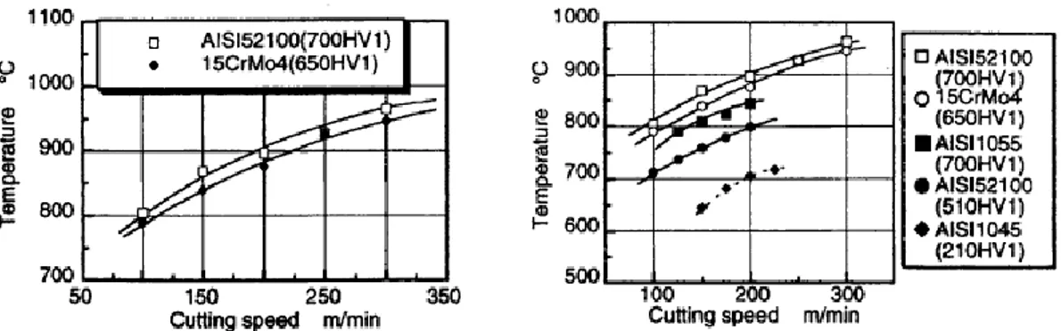
In 1999, Ueda et al [37] studied the influence of cutting parameters and workpiece material on the temperature of the cutting edge Tte (Figure 1.6). A two-color pyrometer
is used to measure the temperature over the thermal radiation of the tool conducted through a hole of an internal tube. Different kinds of steels in different hardness level are investigated. It can be clearly stated that the temperature rises with cutting speed and with the hardness of the workpiece. The investigation of the influence of the workpiece material hardness on cutting temperatures confirms the results of the examination of the machining force. With the increase of the material hardness an increase in cutting force is registered, furthermore with increasing the cutting force cutting energy becomes higher and results in higher temperatures.
Figure 1.6 Influence of cutting speed and work materials on tool temperature: AISI 1045, HV1=210,
a=0.8mm, f=0.15 mm/rev [22]
Studies conducted by Thoenshoff et al [38] on the thermal aspect demonstrates that during the machining operations two areas with different temperatures are formed below the cutting edge:
The maximum temperature on the component surface develops at the beginning of the contact area near the material separation;
A second maximum is produced if the minimum cutting depth is exceeded and only plastic and elastic deformation as well as friction take place.
13
In summary, the power consumption and the heat generation in metal cutting processes are dependent on a combination of the physical and chemical properties of the workpiece material and cutting tool material, cutting conditions and the cutting tool geometry.
1.6 – C
UTTINGM
ATERIALSAnother important aspect in hard turning processes is focused on cutting materials and tool shapes. In hard turning surface roughness and workpiece accuracy are usually comparable to those obtained by grinding processes, for this reason certain boundary characteristics on the applicable cutting tools can be defined with regard to the accuracy of the machined surface:
High indentation hardness of the cutting tool is required in order to prevent deformations of the tool tip in the contact area of tool and workpiece. Usually, it has to be higher than three times the workpiece hardness;
Due to the heat generated in the cutting process, materials with high thermal conductivity are needed to reduce the probability of deviations in the geometric accuracy of the workpiece;
For the high cutting forces and temperatures, tool materials must have high resistance against mechanical stress combined with a high wear resistance;
High thermal stability of the cutting tool material for the high process temperatures that are produced in the area of the contact zone.
Although hard turning is characterized by very high temperatures and specific forces, modern cutting tools are able to stand these thermal and mechanical loads.
14
Mechanical and Thermal Properties Cemented Carbide K 10 Ceramic PCBN PCD
Density (g/cm3) 14-15 3.8-5 3.4-4.3 3.5-4.2 Hardness HV 30 1500-1700 1800-2500 3000-4500 4000-5000
Young's Modulus (GPa) 590-630 300-400 580-680 680-810
Fracture Toughness (MPa) 10.8 2-3 3.7-6.3 6.8-8.8
Temperature Stability (°C) 800-1200
1300-1800 1500 600
Thermal Conductivity (W/(Km)) 100 30-40 40-100 560
Thermal Expansion Coefficient (10-6K-1) 5.4 7.5-8.0 3.6-4.9 4.2-4.9
Table 1.1 Mechanical and thermal properties of different cutting tool materials [38]
Depending on the several aspects above reported on the hard turning processes Al2O3/TiC-ceramics and PCBN are of interest for hard turning operations for their high
tensile strength, fracture toughness and thermal stability. In particular the higher thermal conductivity and lower thermal expansion coefficient lead PCBN tools as the more adapted tool material for hard cutting processes compared to ceramics [39-42].
In fact, Al2O3-ceramic possesses high chemical stability and hardness but the
resistance to fracture is insufficient; the higher toughness and chemical reactivity of SisN4-ceramics cannot be utilized in hard turning and SiC-whisker reinforced ceramics show short tool life.
For this reasons PCBN are the main used cutting tools for turning hardened steels. Figure 1.7 shows tool life in turning of hardened steel, using a low PCBN content (60% of CBN) and an alumina-based ceramic (reinforced with silicon carbide) insert.
PCBN is the cutting tool material with the longest possible tool life. But the composition of the tool material exerts an influence on the wear mechanisms. The material properties of PCBN can be influenced by the PCBN content, the grain size and distribution as well as the composition of the binder phase which can be ceramic or metallic. For hard turning operations usually ceramic binders are preferred. The range of PCBN content in the different tool materials is varied in a percentage of 50% to 90%.
15
Figure 1.7 Efficiency of ceramic and PCBN cutting tool materials: workpiece AISI 4340, HRC=56.0,
V=150 m/min, f=0.08 mm/rev, a=0.15 mm [43]
The mechanical and thermal loads in the cutting process require additional properties of the tool material, especially at low values of uncut chip thickness. The tool material with a lower content of PCBN shows advantages due to lower thermal conductivity and higher toughness. Furthermore, additional properties of the cutting tool material are of importance. This is based upon possible deviations of tool life in relation to different cutting tool manufacturers. Finally, the highest potential for turning hardened steel is shown by PCBN-tools with a low content of PCBN of small grain size.
1.7 – M
ACHINET
OOLTechnology has played an enormous role in advancing the metal working industry and creating opportunities to reduce costs and improve quality. Consider the role technology has played in transforming routine metal cutting operations. At one time machining was very much an operator dependent, skill critical process. Today, CNC machine tools, which operate with mature technology and provide both consistency and reliability, have now become the biggest contributor to part quality and cost.
16
Recent efforts in machine tool development lead to new machine concepts of high-precision lathes to improve the quality of hard turned workpieces significantly (Figure 1.8). The accuracy demands on these machine tools are comparable with grinding machine tools concerning static, dynamic and thermal stiffness as well as accuracy of the spindle system and slides [44, 45]. The application of such types of machine tools enables to reach workpiece qualities in the accuracy range of IT 6-7 in hard cutting under appropriate condition reliability [46].
Figure 1.8 High CNC precision lathe suited for hard turning processes: Mazak: Nexus 200-II, laboratory
of university of calabria
Precision turning lathes with components designed for increased accuracy and high-precision, equipped with NC-controls with high resolution are capable to reach the accuracy of grinding processes. For high grade applications as e.g. for gear components or roller bearings finishing operations need to be made by grinding, for the inaccuracy reached by hard turning with particular attention to the geometrical accuracy as well as on the stiffness of the machine tool: each deviation of the relative position between cutting tool and workpiece reflects its effect on the machined surface.
With the recent conjunction between lathes machine and hydrostatic systems high quality machined parts it is possible to obtain by hard turning processes. By the introduction of hydrostatic guide ways and bearings, resolutions of 0.1 µm in the positioning of the tool tip are possible now. These innovations in lathe machines permit to obtain the final accuracy of grinding by hard turning.
17
Another important aspect of the finishing processes, especially when accuracy is taken into account, is the surface roughness. This aspect represents one of the main limits of the hard turning compared with grinding; in fact, by high precision lathes surface roughness of about Rz=1 µm can be reached, while by fine grinding it is
possible to reach values of Rz lower than 1 µm.
Besides the surface roughness also the surface micro-profile is of high importance for the functional behavior of the machined components especially for the precision parts that are characterized by very fine and smooth profile. Using fine grinding machine tools it is possible to realize the production of these fine contours; in contrast, by hard turning processes this aspect is strictly related to both NC-control resolution and high precision lathe machines.
One of the main advantages of hard turning is the possibility to perform the process in dry conditions avoiding the use of cooling lubricants, on the other hand form errors gain more importance. The temperatures reached during hard turning are usually higher than 500 °C at the tool tip-workpiece contact zone for this reason the thermal effects lead to deviation of parallelism on the surface lines. New developed high-precision lathes offer the possibility to compensate form errors due to thermal effects and to receive a smooth profile without recognizable NC-control steps after dry turning. In order to prevent the form errors, due to the thermal effect, increasing the workpiece quality the application of cooling lubricants seems to be best alternative so that deviation of diameter does not occur during the cutting and the dimensional accuracy is not infected.
1.8 – S
URFACEI
NTEGRITYAmong all the important aspects of a machined part, the functional characteristics (workpiece geometry, surface roughness and surface integrity) need an accurate analysis for the good performance of the component during its application. Mainly attention is usually directed to the surface integrity and attributes, that are particularly influenced by the cutting processes for the complex thermo-mechanical effects typical of the cutting
18
processes. In order to reduce the thermo-mechanical cutting effects and obtain high quality and applicability of machined components, the final cutting operation must be carried out with small cutting depth: low cutting forces, low temperatures and cutting loads reduce dimensional deviations, surface roughness and the influence in terms of surface integrity. Surface integrity includes the presence of micro-cracks, microstructural changes, surface roughness, phase transformations, residual stress, plastic deformation and changes in the microhardness, Figure 1.9 and Figure 1.10.
Figure 1.9 A sketch of the thermo-mechanical cutting loads in different zones and possible surface
microcraks [47]
These factors determine the behavior and service failures of the produced components. For the cited reasons related to the machined surface integrity, a comprehensive understanding of the machining process is essential in order to better design the machining process, choosing the correct process conditions.
Due to the combination of extremely high temperatures and mechanical loads in the tool-tip-workpiece contact zone, the austenite-start temperature of the workpiece material is reached, then for the rapid cooling the workpiece material is self-quenched, so microstructural changes take place and residual stresses influence the surface integrity.
Furthermore the machined surface is characterized by the formation of a thin layer, often called as white layer because of its color when observed by optical microscope or featureless when observed by a scanning electron microscope, Figure 1.10. This
19
microstructural variation seems to be mainly due to the thermal effect caused by hard turning process.
Figure 1.10 An example of surface integrity analysis on hard turned surface of AISI 52100 steel, optical
micrograph: microstructural changes (white and dark layers) and surface roughness [48]
However, before starting to deeply analyze the phase transformations during hard turning it is essential to investigate the material composition and the structure of machined components.
From the literature [49-51] it is widely reported that with white layer formation a considerable increase of the amount of austenite can be observed in the subsurface. White layer consists of over 60% austenite which is a non-etching white component in contradiction to the dark martensite scorching. The martensite components also show a mostly tetragonal twisted lattice.
In order to generate white layers by the machining of hard materials, two conditions must be given:
The contact temperature must exceed austenizing level of the workpiece material;
20
Therefore, a description of the thermo-mechanical mechanisms about the formation of white layers should be able to explain the extremely fast heating phase which is related with austenization.
During hard turning processes, the contact time between tool and workpiece is often less than 0.1 ms, this condition leads to have different material structures if hard turning or grinding operation is performed.
In hard turning, the contact time is very short as well as the time for heat conduction, furthermore hard turning is a single point turning operation; the explanation of these conditions finds its only justification in the specific combination between friction and plastic deformation during hard turning processes. In fact, plastic deformations can produce a high amount of heat in a short time which also heats up the workpiece. The combination of high plastic deformations and extreme short heat up times cause the lattice shearing with the formation of a very fine austenitic grain structure for the rapid cooling that does not allow the grain growth after tool-workpiece contact: a quenching thermal treatment takes place on the machined surface; thus, the combination of martensite and fine grained austenite structure causes the increase of the hardness in the area of the white layer. Consequently, the surface integrity is affected due to the microstructural changes that take place during hard cutting. Also the residual stresses of the austenite material components are clearly shifted towards compressive strain. Under the surface and as a consequence of high mechanical stress, compressive residual stress occurs with a maximum compressive peak positioned near the white-dark layer transition [52].
Finally another important aspect of the hard turning processes is focused on the functional behavior of the machined components.
As it was above mentioned, hard turning deeply influences the surface integrity, and this is an important aspect that must be taken into account for the performance of the component during the applications. This influence on the surface integrity has a direct consequence on the fatigue life behavior; it becomes of real importance especially when rolling contact loads are analyzed [53-55]. Also the in depth residual stresses have an high importance when the fatigue life of hard turned components are taken into account. Figure 1.11 describes the influence of residual stresses and initial workpiece hardness during fatigue life tests.
21
Figure 1.11 Interaction of axial residual stress and hardness on fatigue life [56]
In case of roller contact loads, residual stresses in hard turned surfaces change to values in direction of compressive stresses which is known for its positive influence in case of the fatigue live of components.
Figure 1.12 Residual stress in relation to the oscillation number [57]
Another important component characteristic is the fatigue strength against bending or oscillating loads. Here, sensitive influences from the area of the subsurface, surface topography, microstructure and residual stresses are known. As an example, case hardened components are common in automotive applications. Bending fatigue strength
22
is a main criterion for components because the maximum of the load directly occurs in the surface, the machined area. In this case, the subsurface residual stresses caused by hard machining are of special meaning. For investigations on the influence of hard turning to bending fatigue life, sample pieces with different residual stresses by the turning processes were selected. Stress cycle diagrams of a Wohler fatigue test reveal the influence of hard cutting conditions to the oscillating fatigue strength (Figure 1.12).
The results of the investigations show that the residual stresses are almost not influenced by the number of oscillating loads. A reduction of residual stresses as shown in rolling contact loads does not occur.
To evaluate the productivity of a cutting process the material removal rate is the most important economical parameter.
Compared to the material removal rate, the surface rate gains particular importance in the case of machining smaller workpiece diameters with lower over measures and smaller cutting depth. As a typical example, the efficiency of centerlines grinding of roller bearings can hardly be achieved in turning. However, the productivity effect of the turning process in appropriate cases is due to the high form flexibility. Different surfaces and shapes can be machined with one tool and one machine tool is needed for outer and inner diameter machining. Because of these advantages, in many applications the machining time can be shortened significantly by hard turning, Figure 1.13. However, the final determination of machining times and costs can only be made according to a specific production task.
23
1.9 – A
CCURACY OF THEP
ROCESSThe primary task of hard turning, as a finishing operation, is to ensure the quality and reliability of the parts. The quality criteria of hard turning as a cutting operation can be found in the technical drawings. The most important aspect for any process to be accepted by the industry it should be robust and accurate as far as the performance is concerned. For analysis of the geometrical accuracy in hard turning four characteristics are taken into account, Figure 1.14:
Higher cutting forces;
Dry condition;
Single point form generation;
Minimum value of the depth of cut.
The passive force occurring in hard turning – the component perpendicular to the cutting speed – is a multiple of the main cutting force, while in traditional turning it is only a fraction of this value. The extraordinarily high passive force significantly loads the elements of the machining system, causing elastic deformation and deteriorating the machining accuracy. This issue related to the passive force can be solved increasing the machine tool rigidity. Hard turning is usually performed in dry conditions at relatively high speed resulting in high temperatures, these cause thermal expansion of the workpiece, which also deteriorates the machining accuracy. The surface generating element of hard turning is the single-point tool tip, which shapes the surface of the workpiece and is accompanied by significant force and heat effects. Under such conditions the single-point tool tip reacts sensitively to any irregularities. It abreacts the allowance distinctions, the hardness differences and the other heterogeneities of the material with the creation of machining errors. The fourth aspect influencing the accuracy is the depth of cut. In hard turning this cannot be reduced arbitrarily, although this is possible in grinding. Because of the necessity of a minimum depth of cut, hard turning is followed by higher forces than in grinding, even in the finest smoothing
24
operations. Most unfavorable effects can be eliminated by an increase in the robustness of the machining system: high static and dynamic stiffness of the machine tool and rigid clamping devices for workpiece and tool.
Figure 1.14 Major error driver factors and error sources in precision hard turning [58].
1.10 – C
OSTHard machining applications show high potential to replace grinding operations. The finishing of a hydraulic component is one example for the economical advantages possible by substitution of grinding by turning. Because of many short and different shapes, inner and outer diameter machining, this component is a typical example suited for hard turning.
Compared to the former production by grinding operations, the production sequence is reduced noticeably. Only one machine tool and one single set up is necessary. Reducing the manufacturing process will reduce the number of setting and that will reduce the machining time then the total cost. Workpiece quality achieved in hard turning is at least at the level of the grinding operation. Significant improvements can be
25
seen concerning production times and costs. For instance machining time for batch size is about 60% shorter compared to grinding. In comparison to hard turning, grinding is a more complex process. The repeated conditioning of the grinding wheel occupies the machine itself while tool preparation in hard turning can be done off-line.An additional bonus of hard turning is avoiding cutting fluids. The possibility of dry machining means saving considerable costs otherwise caused by buying, monitoring, treatment and disposal of cutting fluids.
Furthermore cutting leads to more favorable conditions. Due to the possibility of dry machining, there are only chips consisting of not contaminated workpiece material that can easily be recycled [59]. Tool can be disposed (ceramics) or reused after sharpening, but there is no mixture of different materials. Thus, cutting of hard materials can be considered as a very efficient possibility for protection of environment.
1.11 – R
ESIDUALS
TRESSESI
NFLUENCEIt is widely reported that in a finishing process, surface integrity is often a relevant key factor because of its impact on the product performance. In fact, in many cases where unexpected failure occurred, it can be due to the presence of residual stresses which have combined with the service stresses to seriously shorten component life; on the other hand, beneficial residual stresses (usually compressive residual stresses) can be introduced to improve fatigue resistance.
Residual stresses are a tension or compression stresses, that remain after the external cause of the stresses is removed and in hard machining are the results of interactions of thermal and mechanical effects. Three distinct phenomena are thought to contribute to residual stress formation during machining of hardened steel:
1. Mechanical phenomenon: inhomogeneous plastic deformation of the workpiece material. This is inherent to the cutting operation and is usually associated with compressive residual stress;
26
2. Thermal phenomenon: material flow and loads caused by a thermal source. The machining process results in considerable heat generation due to plastic deformation in the shear zone and friction at the secondary and tertiary deformation zones;
3. Metallurgical phenomenon: phase transformations during machining lead to a volume expansion.
The first two phenomena are always present in hard machining, while the third one depends on the machining conditions. Considering the mechanical deformation taking place during cutting in the near-surface region of the workpiece, the workpiece material undergoes compressive plastic deformation ahead of the cutting edge and tensile plastic deformation behind it. If the tensile deformation is greater than the compressive one, the net result will be tensile plastic deformation, which would induce surface compressive residual stresses upon relaxation as the near-surface layer is restricted by the underlying bulk material. The opposite would take place if the net plastic deformation was compressive [60, 61]. During cutting, the surface layer is heated more than the underlying material, and since cooling occurs mainly from the inside by conduction, the surface layer stays hotter than the bulk material after cutting, and tends to expand experiencing compressive stresses. If these compressive stresses exceed the yield strength, the material will be plastically deformed under compression resulting in tensile residual stresses after cooling [62]. The occurrence of phase transformation mainly depends on the cutting temperatures as well as the cooling rate; these are both significant to the workpiece material [63, 64]. When phase transformation takes place, the mechanical and thermal properties of the material change, as well as its grain size. Consequently, residual stresses would be induced due to the non-uniform permanent changes that took place, where the type of residual stresses (whether being tensile or compressive) differs from a material to another.
Component service life is affected to a significant extent by these residual stresses, depending on their nature. Resistance to fatigue, creep and stress corrosion cracking are influenced by the nature and magnitude of residual stresses. In addition, component geometry is likely to be affected, resulting in parts that do not meet required tolerances. Therefore, it is of great importance to predict the residual stresses in the machined
27
component. These types of stresses can be present in any mechanical structure because of their many causes and they may be due to the technological process used to make the component. Manufacturing processes are common causes of residual stress, virtually all manufacturing and fabricating processes such as casting, welding, machining, molding, heat treatment, plastic deformation during bending, rolling or forging introduce residual stresses into the manufactured object. The residual stresses effects on the different properties of a material (fatigue, fracture, corrosion, friction, wear, etc.) can be considerable; in the modern design of mechanical components, residual stresses have therefore to be taken into account. Hence, it is important that the effect of the finishing process on the residual stress profile is accurately predicted, so that the machining parameters can be optimally selected to enhance fatigue life of machined components.
For this reasons related to the machined surface integrity this thesis wants to give a contribute in this direction correlating machining process parameters and workpiece properties to the workpiece surface and subsurface characteristics and residual stress distribution for hard turning processes.
1.12 – F
INITEE
LEMENTM
ODELINGThe main indicators of machined surface integrity are surface roughness, presence of microcracks and residual stresses but also microstructural changes, phase transformation and microhardness changes on the machined surface of hardened steels must be taken into account for the good process feasibility. Furthermore, to make the hard turning process economically competitive, accurate models for surface integrity analysis are needed, that are capable to predict the several aspects related to the surface integrity as a function of the machining conditions, in order to allow the identification of the cutting conditions that will result in the best state (residual stress state, microstructural changes, roughness, etc.) of the component in function of its utilization.
Following this direction, since the early cutting model by Merchant et al [65], based on a simple material flow definition under orthogonal cutting assumption, many
28
researchers in metal cutting are attempting to develop and improve hard turning finite element based models.
Figure 1.15 Temperature (a) and strain (b) analysis by a Deform 3-D post processor [66]
FE software packages consist normally of three parts. These are pre-processing, processing, and post-processing components. The function of the pre-processing is to specify the environment for the actual modeling situation. Both process and material are defined, as well as tool parameters. The solver (or the processing component) is the heart of the program. It is here where the data are treated and all the computations are performed. The third component is the post-processing which is a visualization and analysis tool that provides the user with the capability to analyze, extract, and communicate the results achieved, Figure 1.15.
Since the first finite element studies of the 1970s to the last years several models of the machining processes have been shown by the researchers who work in this direction. Several enhancements have been obtained in the last decade thanks to the use of Finite Element simulations. Numerous researchers used FEM to predict some typical machining variables, such as cutting forces, chip morphology, surface integrity, etc. [67].
In computational mechanisms it is usual to define simulation models which depend on nature of the results. Obviously all the phenomena analyzed during machining processes need appropriate reference scales to be studied: separation of physical effects
29
having large lengths of variation from those with smaller characteristic lengths must be done. Two different scales are introduced to study the turning operations:
Macroscopic scale: to analyze the whole workpiece-tool-machine system particularly the geometry of machined surface;
Mesoscopic scale: to analyze at the tool-tip workpiece scale the chip formation, chip geometry, stresses and temperatures, friction, cutting forces and thermo-mechanical characteristics along the tool-tip.
At the macroscpic scale accurate models have been built to predict the behavior of the workpiece-tool machine system, the cutting forces and the correlated thermal aspects and the roughness and form of the final machined surface.
High evolutive interaction between tool and workpiece is the main characteristic of the machining processes at the macroscopic scale. This interaction is “history” dependent due to the evolution during machining of the workpiece domain.
The cutting law is a central point in machining simulation, for this reason a lot of works are focused in this direction. The first model, based under orthogonal cutting assumptions, was introduced by Merchant [65]. Many efforts and improvements were then proposed. The most relevant enhancements are found in [68] and [69] taking into account wear and thermal aspects and in [70] where thermal diffusion is incorporated. To accurately simulate cutting forces it is necessary to know the instantaneous cutting conditions: cutting speed, feed rate, cutting section, etc. To define the latter geometrical models are needed while the relative motion between workpiece and tool is described by static or dynamic models. To study the dynamic behavior of the process, time domain methods [71] are usually used.
To simulate machining processes it is necessary to have good representative mechanical models; at the macroscopic scale these models are the cutting law with discontinuous cutting condition and dynamic models of the machine.
Concerning the mesoscopic analysis of the machining processes, very relevant enhancements have been registered in the last ten years mainly focused on the reliability of the effectiveness of the obtained results.
30
Some improvements have been registered as concern the flow stress modeling: Johnson-Cook and high shear tests are utilized to identify the material parameters appearing in such law [72]. Most recently some innovative models including the effect of material hardness at high temperatures have been proposed [73].
Friction modeling is generally based on Coulomb models, constant shear models or finally sticking-slide models. Finally chip generation is generally taken into account by means of numerical remeshing in machining modeling, while several advanced damage mechanics models have been implemented to simulate blanking [74].
Today the amount of results provided by machining models is really huge:
Prediction of mechanical variables in machining;
Prediction of chip geometry;
Prediction of thermal variables in machining;
Prediction of tool wear in machining;
Prediction of the surface integrity in machining.
Concerning mechanical variables in machining (strain, stress, cutting forces, etc.) these are dependent on the workpiece parameters (temperature, material type, etc.), cutting tool parameters (material, geometry, etc.) and cutting parameters (cutting speed, feed rate, etc.). Mainly attention was focused on the prediction of cutting forces and pressure distribution on the rake face of the tool [75]. Furthermore the latter studies are pursued to a greater comprehension of the complex physical phenomena underlying the specific machining process: in this sense the development of effective friction models has been pursued by several researchers [76]. Several materials are considered, the most common are steels and aluminum alloys although several efforts are oriented also to titanium alloys, two-phase alloys and other materials.
Since metal cutting is a chip-formation process, the prediction of chip geometry is another important aspect to take into account when modeling is considered. The problem of chip formation and its control has been studied trying to define the mechanism of chip formation, chip flow and chip breaking [73]. Chip flow along the contact length with the tool is a very important factor, because it influences in a relevant
31
way energy dissipation by friction and heat transfer conditions: most of the heat generated in machining is removed from the cutting zone by the chip. Chip control is necessary especially in turning and drilling.
High temperatures in machining are the main cause of unsatisfactory tool life and limitations on cutting speed. Several numerical techniques were proposed to study the thermal problems in machining and to calculate the temperature distributions within both the workpiece and the tool [77]. However the prediction of the thermal aspects is probably the most critical task up to now due to implemented numerical formulation. In fact, most of the numerical analyses of machining are based on the updated-Lagrangian formulation and carry out a coupled thermo-mechanical analysis. In this case only few milliseconds of cutting time can be simulated. This aspect is an heavy limitation for the effectiveness of the numerical modeling, since in this short time thermal steady state cannot be achieved. Furthermore temperature prediction influences other important process variables, such as tool wear and residual stresses.
The above drawback was highlighted by several authors [77], which have proposed different numerical strategies to overcome this problem [78].
Wear prediction in machining has been recently studied by using FEM technique although it still represents a “border” application. A couple of relevant research issues have to be strongly enhanced to achieve an effective prediction: the former is related to the reliability of the calculated temperature field, the latter is connected to the absence of predictive models for coated tool.
Whereas these problems, several authors tried to model tool wear by FEM [55, 60] taking into account advanced tool wear models, mainly based on diffusive wear models. More in detail, Nouari and Molinari [70] proposed a tool wear model considering the diffusion mechanism to predict uncoated tungsten carbide wear when cutting steels are machined. They also investigated the influence of the process variables as well as of the tool geometry on the tool wear. However, in the last few years the research on tool wear mechanism appears to be reduced, although tool wear prediction is one of the most critical issues. Probably the reason is strictly related to the unreliability of temperature prediction in machining. Only once this problem is solved, tool wear prediction can be heavily carried out and extended to coated tools.
32
Finally the reliability of mechanical components depends to a large extent on the physical state of their surface layers. This state includes the distribution of residual stresses induced during the machining process.
Residual stresses can enhance or impair the ability of a component to withstand loading conditions in service (fatigue, creep, cracking, etc.), depending on their nature: compressive or tensile, respectively. Therefore, prediction and control of the residual stresses in machining is absolutely necessary. For these reasons several researchers were oriented on this field [70, 79] even if more efforts must be done to improve the prediction of the surface integrity in terms of advanced flow stress models, temperature prediction and modeling of tool wear when advanced tool materials are used.
It is evident that the finite element method (FEM) simulations are today a very important and helpful instrument in hard turning processes analysis, and several are the researchers who work in this field with the aim to give a valid contribute to the science. So the results that will be showed direct to a more consistent utilize of the FEM in the tools design and in the simulation of the hard turning process.
1.13 – M
OTIVATION OF THEP
RESENTW
ORKThe following observations explain the motivation for the present thesis:
1. Recent researches have shown that machining of components directly in the hardened state can lead to substantial productivity improvement by eliminating extra processing steps such us grinding. For this reason the hard turning process is going to be applied in industry with the aim to replace the costly and slow grinding process in finishing mechanical components. Furthermore in the latter, the relatively more aggressive grinding process parameters employed under typical production conditions could result in the deterioration of the surface integrity of hardened components and hence on their life under service conditions;
33
2. In machining of hardened materials, maintaining surface integrity is one of the most critical requirements. Often, the major indicators of surface integrity of machined parts are surface roughness and residual stresses. However, the material microstructure also changes on the surface of machined hardened steels and this must be taken into account for process modeling. Therefore, in order for manufacturers to maximize their gains from utilizing hard finish turning, accurate predictive models for surface integrity are needed, that are capable of predicting also both white and dark layers formation as a function of the machining conditions;
3. The good agreements, between numerical and experimental results, showed by the several researchers in the literature of the hard turning processes induce to an increasing use of the FEM for the optimization of cutting tool design (tool material and geometry, coatings) and cutting conditions (cutting speed, feed rate, depth of cut) such that product quality, productivity, and tool life are maximized.
The above observations indicate that it is necessary to:
1. Have a series of experimental cutting tests conducted under several cutting conditions;
2. Study the effect of cutting tool edge geometry and cutting conditions (cutting speed, feed rate and initial workpiece hardness) in terms of surface integrity: residual stresses profile, microstructural changes, phase transformations, etc.;
3. Develop a valid methodology and Finite Element Model to predict the several aspects related to the surface integrity during hard turning process.
![Figure 1.1 Qualitative overview of the capability of hard turning and grinding [11]](https://thumb-eu.123doks.com/thumbv2/123dokorg/2876180.9873/13.892.335.650.423.752/figure-qualitative-overview-capability-hard-turning-grinding.webp)
![Figure 1.11 Interaction of axial residual stress and hardness on fatigue life [56]](https://thumb-eu.123doks.com/thumbv2/123dokorg/2876180.9873/29.892.272.718.133.402/figure-interaction-axial-residual-stress-hardness-fatigue-life.webp)


