Open Access. © 2018 A. A. Pisano and P. Fuschi, published by De Gruyter. This work is licensed under the Creative Commons Attribution-NonCommercial-NoDerivatives 4.0 License
Research Article
Aurora Angela Pisano* and Paolo Fuschi
Stress evaluation in displacement-based 2D
nonlocal finite element method
https://doi.org/10.1515/cls-2018-0010 Received Apr 06, 2018; accepted Apr 09, 2018
Abstract: The evaluation of the stress field within a
non-local version of the displacement-based finite element method is addressed. With the aid of two numerical ex-amples it is shown as some spurious oscillations of the computed nonlocal stresses arise at sections (or zones) of macroscopic inhomogeneity of the examined structures. It is also shown how the above drawback, which renders the stress numerical solution unreliable, can be viewed as the so-called locking in FEM, a subject debated in the early seventies. It is proved that a well known remedy for lock-ing, i.e. the reduced integration technique, can be success-fully applied also in the nonlocal elasticity context.
Keywords: Nonlocal displacement-based finite element
method; 8-nodes Serendipity quadrilaterals; Nonlocal stress locking; Reduced integration technique
1 Premises and motivations
Nonlocal approaches in the field of continuum mechan-ics are nowadays widely used in a number of engineer-ing applications (see e.g. [1–3]). The common feature of such approaches relies on the need to describe at a macro-scopic level phenomena arising at a micromacro-scopic level, i.e. within the microstructure of the constituent material, that, indeed, play a significant role in the right description of the material/structural behavior. Typical examples of such cir-cumstance can be traced back to the early seventies when dealing with the description of the stresses at a tip of a crack (see e.g. [4]) till more recent problems facing the analysis of structural elements made of materials contain-ing nano-particles [5]. Wave dispersion, strain softencontain-ing,
*Corresponding Author: Aurora Angela Pisano:Department PAU - via Melissari, I-89124 Reggio Calabria, Italy, University Mediter-ranea of Reggio Calabria; Email: [email protected]
Paolo Fuschi:Department PAU - via Melissari, I-89124 Reggio Cal-abria, Italy, University Mediterranea of Reggio Calabria
concomitant size effects are, among others, well known ex-amples (see e.g. [6–8] and references therein).
It is also well known that classical continuum me-chanics fails in describing the above problems for the ab-sence in the constitutive laws of any information coming from the microstructure. Indeed, the above referred non-local continuum approaches succeed in this challenge by introducing in the classical modeling an internal length
material scale while keeping the hypothesis of
continu-ity. There are different constitutive hypotheses that give rise to different nonlocal continuum theories and an huge amount of approaches and related numerical techniques proposed to face real problems (see e.g. [6] and [2] just to quote two milestone works). The list of quotable contribu-tions is very long and out of the scope of the present pa-per. The nonlocal approach hereafter referred is the one known as nonlocal integral approach of Eringen and co-workers (see e.g. [9, 10]). It is applied within the elastic-ity field and in a shape proposed by the authors in [5, 11– 14] and there named strain-difference-based nonlocal
inte-gral elasticity model. The stress is expressed as the sum
of two contributions: a local standard one and a nonlo-cal one given in integral form and in terms of an averaged
strain difference field. A nonlocal version of the finite
ele-ment method, named NL-FEM, was also proposed in the above quoted papers on the base of a nonlocal total
po-tential energy functional whose optimality conditions yield
the governing equations of the pertinent boundary-value-problem governed, besides the nonlocal stress-strain law, by standard equilibrium and compatibility conditions. The details of such formulation are given in the quoted paper and will be only briefly summarized hereafter. The main goal of the present paper is however strictly related to the already implemented NL-FEM and, as declared in the ti-tle, it concerns the stress evaluation within a displacement-based nonlocal formulation of such method.
The right evaluation of (nonlocal) stresses is, with no doubts, of utmost importance within a nonlocal numerical formulation. Stress based criteria to face fracture mechan-ics problems might be consistently rephrased for example, or nonlocal limit analysis for structural elements made of nonlocal materials, such as metal matrix nanocomposites, might be fields of possible fruitful application of the
NL-FEM, but, obviously, many other nonlocal elastic problems may gain advantage from, or cannot renounce to, a correct description of the stress field. To the authors knowledge however this point has not been sufficiently addressed in the relevant literature and even in their previous works. Very often, the reliability and effectiveness of a nonlocal numerical approach is verified only by plotting the (nonlo-cal) strains. In many numerical applications, also arising from different nonlocal theories and hypotheses, the stress distribution is simply not given.
The cited NL-FEM was implemented by the authors with reference to plane stress cases and for 2D 8-node Serendipity displacement-based finite elements (FEs). When applied to benchmark problems in which nonlocal-ity plays a prominent role such elements show indeed reli-able results in terms of strain distributions but they defini-tively fail in stress description. Precisely, spurious
oscilla-tions come out making the solution in terms of stress
com-pletely unreliable. To face this problem, a numerical tech-nique well known in the realm of standard FEM is pro-posed, namely the reduced integration procedure. The lat-ter, first conceived by Zienkiewicz in the early seventies [15] see also [16–18] is, as known, one remedy among oth-ers, to treat the so-called locking in FEM. A sort of
nonlo-cal locking can in facts be envisaged sharing many
com-mon features with the classical locking in FEM for a long debated, see e.g. [19, 20] and references therein. On taking into account that we are dealing with second order quadri-lateral (nonlocal) elements and avoiding the circumstance of incompressible material, shear-locking and volumetric locking have to be excluded. The spurious stress oscilla-tions observed at zones with (nonlocal) stress concentra-tion rather resemble the so-called stress-locking exhibited by FEs with embedded discontinuities, see [21, 22] and ref-erences therein.
Two cases study are analyzed in Section 4 showing how an old numerical technique can be successfully ap-plied in a novel version of the FEM. Some other consider-ations will be carried out in the same section concerning the possible source of stress-nonlocal-locking related to the analytical formulation of the method. The latter is briefly summarized in the next two sections. Concluding remarks point out the reached results drawing possible future steps of the ongoing research this paper belongs to.
Notation: Bold-face letters are used for vectors and tensors. The “dot" and “colon" products between vectors and tensors denote simple and double index contraction operations, respectively. For instance: u · v = uivi, σ : ε =
σijεij, σ : n = σijnij, D : ε = Dijhkεhk. The symbol := means
equality by definition. In Section 3, dealing with NL-FEM,
a standard matrix notation is also used. Other symbols will be defined in the text at their first appearance.
2 The nonlocal integral model
The constitutive assumption which characterizes the adopted model is (see [12] for details):
σ(x) = D(x) : ε(x) − α ∫︁
V
J(x, x′) :[︀ε(x′) − ε(x)]︀ d V′ (1)
∀(x, x′)∈V ,
where: σ(x) and ε(x) denote elastic stress and strain sec-ond order tensors, respectively; D(x) is the fourth order tensor of the elastic moduli (assumed variable in space to deal with macroscopic inhomogeneities of the material); J(x, x′) is a nonlocal operator defined next; α is a
(nonlo-cal) material parameter to be fixed on the base of experi-mental findings on the material in use. Looking at the r.h.s. of Eq. (1), besides the standard local first term of the stress (pertaining to a local material phase), a convolution in-tegral appears as second term of the stress (pertaining to a nonlocal material phase). The latter defines a nonlocal contribution to the stress σ(x) arising from the postulated nonlocal behavior of the material whose influence is gov-erned by the fixed material parameter α. The nonlocal op-eratorJ(x, x′) has the following shape:
J(x, x′) :=[︀ 𝛾(x)D(x) +𝛾(x′)D(x′)]︀ g(x, x′) − k(x, x′) (2) ∀(x, x′)∈V with: 𝛾(x) := ∫︁ V g(x, x′) d V′; (3a) g(x, x′) := λ exp(︀−|x− x′|/ℓ)︀ ; (3b) k(x, x′) := ∫︁ V g(x, z)g(x′, z)D(z) d Vz. (3c)
By inspection of Eq.(1) and positions (2-3), all derived by a thermodynamically consistent formulation given in [11], it appears how the strain-difference field at points (x, x′), namely[︀ε(x′) − ε(x)]︀ is eventually weighted by the
function g(x, x′), known as attenuation function, through the operators 𝛾(x), k(x, x′) and J(x, x′) depending on it. Function g(x, x′), here assumed as bi-exponential with λ = 1/2πℓ2 given by the normalization condition ∫︀
V∞g(x, x
′) d V′= 1 (V
space in which V is embedded), introduces a second non-local material parameter of this adopted model. Such pa-rameter, namely the internal length material scaleℓ de-pends on the microstructure’s features, e.g. on the size and spacing of major inhomogeneities at small scale. The choice of the analytical shape of g(x, x′) and of the numeri-cal value ofℓconcerns the connection between the (macro-scopic) nonlocal integral continuum theory and the real nonlocal material behavior at atomistic (small) scale. The attenuation function decreases with increasing Euclidean distance between point x and x′ in V vanishing beyond the so-called interaction radius or influence distance, say
LR. The nonlocal strain at a given point x is affected only
by points x′closer than LR. In the limit of a local behavior,
i.e. forℓ →0, g(x, x′) turns into a Dirac delta. The ability
of g(x, x′) in capturing nonlocal phenomena is often tested by atomistic simulations (see e.g. [23–25]).
3 The 2D displacement-based
nonlocal finite element method
The governing equation of a boundary-value-problem con-sidering a constituent material obeying Eq.(1) can be ob-tained as the optimality conditions of the following non-local total potential energy functional:
Π[︀u(x)]︀ := 1 2 ∫︁ V ∇u(x) : D(x) :∇u(x) d V + (4) +α 2 ∫︁ V ∇u(x) :𝛾2(x)D(x) :∇u(x) d V + −α 2 ∫︁ V ∫︁ V ∇u(x) :J (x, x′) :∇u(x′) d V′d V + − ∫︁ V b(x) · u(x) d V − ∫︁ St t(x) · u(x) d S.
In Eq. (4): u (x) is the unknown displacement field in V;
b(x) are the body forces; t (x) are the surface tractions act-ing on St = S − Suwhere S denotes the boundary surface
of V and Suthe portion where u (x) satisfy given kinematic
boundary conditions, say u (x) = u (x).
A displacement-based nonlocal FEM can be formu-lated starting from a discretized version of Eq. (4) easily ob-tainable once introduced a modeling of the displacement field in terms of nodal displacement of the, let’s say Ne,
fi-nite elements in which the domain V is subdivided. Pre-cisely, denoting with (·)n a quantity referring to the nth
FE in the mesh (with n = 1, 2, ...Ne) and with Nn(x)
and Bn(x) the matrices of the interpolation (shape)
func-tions and their derivatives, respectively, the displacement FE model is expressed by:
u(x) = Nn(x)dn, (5a)
ε(x) = Bn(x)dn ∀(x, x′)∈Vn, (5b)
where dnis the vector collecting the nodal displacements
of the element #n occupying the volume Vn.
Substitut-ing 5(a,b) in (4) and rearrangSubstitut-ing, the discretized version of Eq. (4) can be given the shape:
Π [dn] = 1 2 Ne ∑︁ n=1 dTnklocn dn + α 2 Ne ∑︁ n=1 dTnknonlocn dn+ (6) −α 2 Ne ∑︁ n=1 Ne ∑︁ m=1 dTnknonlocnm dm − Ne ∑︁ n=1 dTnfn.
In equation (6) the following positions have been made:
klocn := ∫︁ Vn BTn(x) D (x) Bn(x) d Vn, (7a) fn := ∫︁ Vn NTn(x) b(x) d Vn + ∫︁ St(n) NTn(x) t(x) d Sn, (7b)
defining, as usual, the standard (local) element stiffness matrix and equivalent nodal force vector, respectively;
knonlocn := ∫︁ Vn BTn(x)𝛾2(x) D (x) Bn(x) d Vn, (8a) knonlocnm := ∫︁ Vn ∫︁ Vm BTn(x)J (x, x′) Bm(x′) d Vmd Vn, (8b)
defining the nonlocal element stiffness matrices.
Remembering the definitions of the nonlocal opera-tors 𝛾(x) andJ (x, x′), given by Eqs. (3a) and (2) respec-tively, as well as the property of the attenuation function
g (x, x′), here assumed in the shape of Eq. (3b) that
van-ishes beyond the interaction radius LR, the following can be stated. The nonlocal matrices (8a,b) capture the nonlo-cal effects exerted on the current element #n by its neigh-bor elements, i.e. the ones falling within an influence zone of radius LRand centered on #n, whose number, say Me≪
Ne, depends on LRand on the elements’ size. In a FE
con-text it is understood that: x is the position vector of the cur-rent Gauss point (GP) of the curcur-rent element #n and x′is the position vector of the current GP of the current neigh-bor element of #n, say #m with m = 1, 2, . . . Me; the
in-fluence zone (a circle of radius LRin 2D) is the centered at each GP of element #n.
Skipping all the details of the NL-FEM implementation given in [12], that can be referred for a deeper comprehen-sion, it is worth noting that the assembling of the elements matrices klocn , knonlocn and knonlocnm , the latter being a set of
nonlocal matrices of element #n (a self-stiffness matrix, tained for m = n, plus all the cross stiffness matrices ob-tained for m = 1, 2, . . . Mewith m ≠ n) yields a nonlocal
global matrix (which can be proved to be positive definite
and symmetric) whose formal expression is:
̂︀ K = Ne ∑︁ n=1 CTnklocn Cn (9) + α Ne ∑︁ n=1 [︃ CTnknonlocn Cn − Me ∑︁ m=1 CTnknonlocnm Cm ]︃ .
In equation (9) Cnand Cm are the connectivity matrices
enlarging the element matrices to global dimensions and the sums of such enlarged elements’ matrices mimic the assembling procedure. It is clear that the nonlocal global matrix ̂︀Kis more populated than in the standard local FEM due to the presence of the elements’ cross-stiffness matri-ces knonlocnm .
3.1 Stress evaluation
As said, the NL-FEM was already numerically imple-mented by the authors, precisely a 2D formulation for plane stress problems has been developed and success-fully applied to quite a few examples and benchmark prob-lems ([12, 13]).
The implemented NL-FEs are isoparametric 8-nodes Serendipity quadrilaterals. This choice was suggested by a number of reasons well known in the standard (local) FEM formulation, that is: i) second-order elements outper-form first-order ones in problems with stress concentra-tions being also ideally suited for the analysis of (station-ary) cracks, one of the future goal of the present promoted NL-FEM; ii) second-order elements capture geometric fea-tures, such as curved edges, with fewer elements than first-order ones providing also high accuracy in stress concen-tration regions; iii) they do not suffer shear locking when model bending; iv) over all, their isoparametric formu-lation represents the biggest breakthrough in the imple-mentation of the FEM for its capability to model problems (structures) geometries of any shape and size by working on mapping.
All the numerical integrations have been carried on by Gauss quadrature integration rule with a full integration,
i.e. taking into account 3x3 GPs per element. It is worth
not-ing that for second-order elements Gauss integration is the
more used (at least in the local context) because it is effi-cient and it is especially suited to the polynomial product interpolation adopted in these elements, a quality service-able also in the present nonlocal context.
The global (nonlocal) equation system was solved by a standard and robust commercial package, employing the RTR Cholesky factorization for symmetric positive definite matrices with an iterative refinement on the solution vec-tor to improve the accuracy, getting the (nonlocal) nodal displacements and the strains at the GPs of the NL-FEs.
As shown by the numerical findings reported in the quoted papers of the authors and as briefly illustrated in the next section, the (nonlocal) strains appear very good: they are not affected by mesh dependence, they are able to capture size-effects and, even if not compared with lab-oratory findings on real prototypes practically absent in the relevant literature, they look very sensible and reliable showing also the right sensitivity to the parametric analy-ses obtained by varying the fixed values of the nonlocal material parameters α and ℓalso in presence of macro-scopic inhomogeneities.
Nevertheless, when such solutions (in terms of non-local strains) were used back in a discretized FE form of Eq. (1) to get the stresses at the GPs of the NL-FEs, such stresses result to be affected by spurious oscillations. As observed in Section 1, avoiding the case of incompress-ibility which might produce volumetric locking, a sort of
nonlocal-stress-locking can be envisaged. Precisely,
spuri-ous stress oscillations arise at zones with macroscopic in-homogeneities spreading all over the adjacent zones ren-dering the stress solution completely unreliable. The pro-posed remedy to such drawback is ancient and is a nu-merical remedy, namely the reduced integration proposed by Zienkiewicz in [15–17], see also [18–20] for a deeper comprehension. It is worth reminding that full integration means that the minimum integration order required for an exact integration of the strain energy for an undistorted el-ement with linear material properties is used. The reduced integration is then the integration rule that is one order less than the full integration one.
In the 8-nodes isoparametric NL-FEs here adopted re-duced integration means an integration performed on 2x2 GPs per element. As shown in the next section such re-duced integration does not affect the response in terms of (nonlocal) strains that is it does not influence the com-puted displacements and therefore most likely it does not affect the evaluations on the terms of the nonlocal global matrix ̂︀K. Indeed, the reduced integration improves dra-matically the response in terms of stresses computed at the GPs of the NL-FEs yielding, for example, the “exact solu-tion" in terms of stresses for a benchmark problem
ana-lyzed in next section and characterized by a known con-stant stress on the whole BVP domain.
By investigating the trend of the single stress contri-butions at the r.h.s. of Eq. (1), taking into account Eqs. (2, 3) and obtained by full and reduced integration, it has been noted that the “source of stress oscillations" is the integral over the whole domain V of the nonlocal opera-torJ (x, x′). The reduced integration definitely overcome this drawback. It is worth noting that the operatorJ (x, x′) is also integrated when computing the cross-stiffness el-ement matrices knonlocnm , see Eq. (8b), but in this case the
integral is carried on or, let’s say, is confined to, the sub-domains (volumes) Vnand Vmof the involved elements, a
circumstance that, as numerically detected, does not pro-duce any form of instability.
The idea of speaking of nonlocal-stress-locking relies firstly on the nature of the observed stress oscillations (ob-tained by full integration) for which the term to describe them seems appropriate but, secondly, it relies on the ob-servation that it resembles, at least in many formal as-pects, the so-called stress-locking exhibited by (local) FEs with embedded discontinuities, see e.g. [21, 22] and refer-ences therein. Such circumstance has however to be fur-ther investigated being just an hint for a better needful un-derstanding of the observed phenomenon.
Concerning the adoption of the reduced integration in the present nonlocal elastic context the following further general remarks can be made.
Remark 1. A FE displacement-based model, also in the present nonlocal form, is inexact and usually it errs by be-ing too stiff. Borrowbe-ing from [18], this is a congenital er-ror of any displacement-based formulation where the dis-placements are “on the whole" underestimated and the stiffness of the model is “on the whole" overestimated as a results of the “internal displacement constrains" implic-itly imposed on the solution by the assumed displacement model. If the error made with a reduced numerical integra-tion compensates for the overestimaintegra-tion of structural stiff-ness due to finite element discretization improved results may be expected.
Remark 2. Reduced integration leads (in the local con-text) to rank deficiency of the stiffness matrix and “spuri-ous" zero energy modes or “hour-glass" modes. This draw-back seems here mitigated by a stiffness matrix which for each NL-FE collects contributions coming from the neigh-bors elements. Moreover, the hour-glass modes, character-ized by strains not detected at the (reduced) integration points so furnishing nonphysical response modes with de-formations but no strains (zero-energy modes), reduce as
known to only one mode in the second-order Serendipity 8-nodes quadrilaterals and it does not propagate to neigh-bors elements so it will not occur in a mesh with more than one element as it happens in the local FEM.
Remark 3. On taking into account what observed above on the integration of the nonlocal operatorJ (x, x′), which is integrated on the whole V in Eq. (1) being responsible of the stress oscillations and integrated only on the subdo-mains Vnand Vmwhen computing the cross-stiffness
ma-trices of Eq. (8b), a selective reduced integration might be also envisaged when dealing with more complex nonlocal problems in which reduced integration could be used only for the stress evaluation by Eq. (1).
At closure of this section it is difficult, as in the stan-dard FEM formulation, to provide a general guideline, applicable to all types of problems, on whether to use reduced or higher order integration. It is reasonable to assume, as in the standard FEM, that reduced integra-tion is generally better suited for undistorted elements as the ones considered in the following examples, whereas higher order (or full) integration tends to work better as the element becomes more distorted. To this concern fur-ther investigations within the nonlocal context are the ob-ject of an ongoing research.
4 Cases study
4.1 Bar-like structure under tension
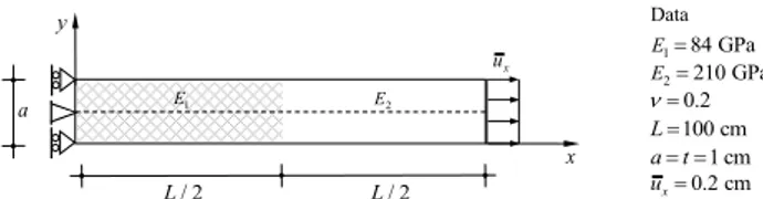
The nonlocal elastic nonhomogeneous bar-like structure of Figure 1 is analyzed first. This problem was solved in [11] following a 1D formulation, i.e. referring to the bar’s axis (dashed line) in Figure 1 and assuming the bar, of unit cross-section, fixed at the end x = 0 and subjected to a given displacement ux= 0.2 cm at the end x = L = 100 cm.
The bar is characterized by a macroscopic inhomogeneity being made, by hypothesis, of a material with a piecewise homogeneous Young modulus E1= 84 GPa and E2= 210
GPa in the first and in the second half, respectively. The Poisson ratio is ν = 0.2 on the whole bar. The nonlocal
Data 2 210 GPa E184 GPa E 100 cm L 0.2 cm x u 1 cm a t 0.2 x y x u 2 E / 2 L / 2 L 1 E a
Figure 1:Bar-like structure in tension: geometry, loading, boundary conditions and material data.
a) b)
c) d)
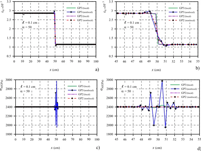
Figure 2:Local and nonlocal solution obtained with full (GP3 curves) and reduced (GP2 curves) integration for the bar of Figure 1 with inter-nal length ℓ = 0.1 :a) and b) strain εxand zoom at the bar mid zone respectively; c) and d) stress σxand zoom at the bar mid zone respec-tively.
material parameters α is assumed equal to 50 while three valuesℓ = 0.1, 0.5, 1 (cm) of the internal length will be assumed next.
The solution procedure in 1D is quite simple because of the stress σxbeing constant in the whole bar for
equilib-rium. Starting from a 1D version of the constitutive model (1) it is easy to get a governing Fredholm integral equation of the second kind which can be uniquely solved, for in-stance by a successive iteration procedure, applying even-tually the bar boundary conditions. The analytical 1D so-lution in terms of strains and stresses, obtained following the rationale given in [11] and not reported for brevity, has been considered as benchmark for the here followed 2D NL-FEM treatment of the same problem. To this concern in the 2D simulation (refer again to Figure 1) apposite con-strains have been applied on the fixed edge at x = 0 that, together with a low value of the Poisson ratio, render the 2D bar-like structure as much as possible equivalent to its
1D version for which the alternative analytical solution is available.
The bar-like structure has been discretized with one row of 100 8-nodes NL-FEs Serendipity quadrilaterals and the obtained results are given in Figures 2-4) for three val-ues of the internal lengthℓassumed in the numerical anal-yses.
Figures 2(a,b), 3(a,b) and 4(a,b) plot, along the bar’s axis, the local and nonlocal strains εxforℓ= 0.1, 0.5 and
1 respectively, all the Figures (b) give a zoom of the curves of Figures (a) around the midsection of the bar, i.e. where the Young modulus abruptly changes. By inspection of the strain curves it appears how, beyond the already known difference between the local and nonlocal strains, no sig-nificant mismatch exists, they are coincident in practice, between the strain curves (GP3 nonlocal and GP2 nonlo-cal) obtained by full and reduced integration. The analyt-ical benchmark solution in terms of nonlocal strains, not
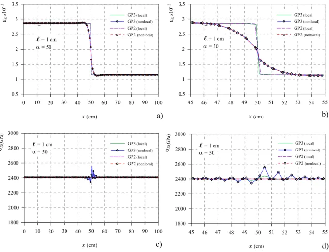
a) b) c) d) 0 10 20 30 40 50 60 70 80 90 100 1 2 3 0.5 1.5 2.5 3.5 GP3(local) GP3(nonlocal) GP2(local) GP2 (nonlocal) x (cm) εxx 10 - 3 l= 0.5 cm α = 50 0 10 20 30 40 50 60 70 80 90 100 1800 2200 2600 3000 2000 2400 2800 GP3GP3(local) (nonlocal) GP2(local) GP2 (nonlocal) x (cm) σx(GPa) l= 0.5 cm α = 50 46 48 50 52 54 45 47 49 51 53 55 1800 2200 2600 3000 2000 2400 2800 GP3(local) GP3(nonlocal) GP2(local) GP2 (nonlocal) x (cm) σx(GPa) α l= 0.5 cm= 50 46 48 50 52 54 45 47 49 51 53 55 1 2 3 0.5 1.5 2.5 3.5 GP3(local) GP3(nonlocal) GP2(local) GP2 (nonlocal) x (cm) εxx 10 - 3 l= 0.5 cm α= 50
Figure 3:Local and nonlocal solution obtained with full (GP3 curves) and reduced (GP2 curves) integration for the bar of Figure 1 with inter-nal length ℓ = 0.5 :a) and b) strain εxand zoom at the bar mid zone respectively; c) and d) stress σxand zoom at the bar mid zone respec-tively.
potted for clarity, is also exactly the same of the curves ob-tained by 2D NL-FEM treatment.
On the contrary, looking at Figures 2(c,d), 3(c,d) and 4(c,d) plotting the local and nonlocal stress σx for
ℓ= 0.1, 0.5 and 1 respectively, where once again all the Figures (b) give a zoom of the stress curves around the mid-section of the bar, the following can be stated. The previ-ously discussed spurious nonlocal stress oscillations, here named nonlocal-stress-locking, arise at the bar midsec-tion spreading around it when using full integramidsec-tion (GP3 curves). The nonlocal stresses given by reduced integra-tion (GP2 curves) give conversely the right soluintegra-tion, i.e. a stress distribution constant over the whole bar by equilib-rium and coincident with the local and analytical ones as it has to be. The discussed effectiveness of the reduced in-tegration is so proved.
4.2 Plate with inclusion
The nonhomogeneous square plate of Figure 5 has been analyzed focusing the attention on the nonlocal stress evaluation.
The same example was treated in [12] giving the re-sponse only in terms of nonlocal strains and showing the sensitivity of the solution to the nonlocal material param-eters α andℓ, the mesh independency, the ability of the NL-FEM in capturing size-effects.
The plate geometry, material data, loading and bound-ary conditions are also given in Figure 5. A macroscopic in-homogeneity is given by a squared inclusion at the plate’s core with a Young modulus E1 = 84 GPa. In the
remain-ing part of the plate a Young modulus E2 = 210 GPa is
assumed. The Poisson ratio is ν = 0.2 while the value
α = 50 has been assumed in the NL-FE analysis performed
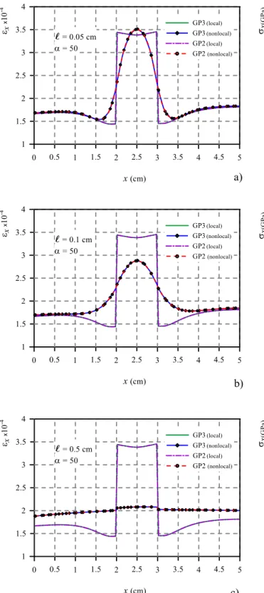
with a mesh of 40x40 8-nodes, isoparametric, Serendip-ity quadrilaterals. The valuesℓ= 0.05, 0.1, 0.5 (cm) have
a)
b)
c)
d)
Figure 4:Local and nonlocal solution obtained with full (GP3 curves) and reduced (GP2 curves) integration for the bar of Figure 1 with inter-nal length ℓ = 1 :a) and b) strain εxand zoom at the bar mid zone respectively; c) and d) stress σxand zoom at the bar mid zone respec-tively. Data 2 210 GPa E1 84 GPa E 0.2 1 cm; 0.5 cm ax0.001 cmt u x y 2a a 2a x u 2a a 2a 1 E 2 E
Figure 5:Plate with inclusion: geometry, loading, boundary condi-tions and material data.
been considered. The plate is fixed at edge x = 0 and it is subjected to imposed uniformly distributed displacements
ux= 0.001 cm at the edge x = 5a (with a = 1 cm).
Figures 6(a-c) show, along the mid side section of the plate at y = 2.5a, the nonlocal strains εxagainst the
lo-cal ones, both computed with full and reduced integration.
Beyond the known mismatch between the local and nonlo-cal strains εx, by inspection of the nonlocal strains curves,
named GP3 nonlocal and GP2 nonlocal, it is confirmed also in this case that full or reduced integration does not affect the nonlocal solutions in terms of strains.
Figures 7(a-c) plot the stress σx, i.e. the preeminent
stress component along the loading direction, at the mid side section for y = 2.5a. Once again the stresses obtained by a full integration (GP3 nonlocal curves) show spurious oscillations arising at sections where the Young modulus changes. The latter spread within the surrounding areas rendering the nonlocal stress solution unreliable. The non-local stresses given by reduced integration (GP2 nonnon-local curves) eliminate completely the undesirable oscillations. It is worth noting that in both examples the “ampli-tude" of the spurious oscillations increases with decreas-ing values of the internal length material scaleℓ.
a)
b)
c)
Figure 6:Local and nonlocal strain profiles εx, obtained with full (GP3 curves) and reduced (GP2 curves) integration for the plate of Figure 5, at the mid section y=2.5a :a) for ℓ = 0.05; b) for ℓ = 0.1; c) for ℓ = 0.5.
a)
b)
c)
Figure 7:Local and nonlocal stress profiles σx, obtained with full (GP3 curves) and reduced (GP2 curves) integration for the plate of Figure 5, at the mid section y=2.5a :a) for ℓ = 0.05; b) for ℓ = 0.1; c) for ℓ = 0.5.
5 Concluding remarks
The paper has very briefly summarized a nonlocal formu-lation of the displacement-based finite element method previously implemented by the authors with reference to a nonlocal elastic constitutive model of integral type also allowing to treat structures made of nonhomogeneous ma-terials. Attention has then been focused on the goal of the work, i.e. the stress evaluation within the nonlocal FEM procedure.
A numerical drawback, characterized by the outset of spurious stress oscillations at sections (or zones) of macro-scopic inhomogeneities of the examined nonlocal elastic structures here given by abrupt changes of the Young mod-ulus, has been pointed out. A sort of nonlocal locking, named nonlocal-stress-locking, has been envisaged.
A well known numerical technique to avoid locking in FEM has been proposed in this context, i.e. the re-duced integration. The numerical findings on the two tack-led problems, one of which allowing an alternative analyt-ical solution useful for comparison purposes, seem to val-idate the proposed remedy.
The topic, far to be exhaustively treated, has to be viewed as the authors’ will of sharing what experienced in the numerical determination of the stresses in a nonlocal context treated by a displacement-based NL-FEM proce-dure. The proposed remedy opens the way to a wide range of problems as, for example, the stresses determination in the field of (nonlocal) elastic fracture mechanics with the consequent adoption of nonlocal stress-based criteria.
References
[1] A.C. Eringen. Nonlocal continuum field theories. Springer-Verlag New York (2002).
[2] Z.P. Bažant, L. Cedolin. Stability of structures: elastic, inelastic, fracture and damage theories. World Scientific Publishing Com-pany Ed. (2010).
[3] M.A. Eltaher, M.E. Khater, Samir A. Emam. A review on nonlo-cal elastic models for bending, buckling, vibrations, and wave propagation of nanoscale beams. Applied Mathematical Mod-elling 40 (2016) 4109-4128.
[4] A.C. Eringen, B.S. Kim. Stress concentration at the tip of a crack. Mechanics Research Communications 1 (1974) 233-237. [5] P. Fuschi, A.A. Pisano. Ultimate load prediction of MMNCs
struc-tures. Composites Part B 125 (2017) 175-180.
[6] Z.P. Bažant, M. Jirásek. Nonlocal integral formulations of plas-ticity and damage: survey of progress. Journal of Engineering Mechanics 11 (2002) 1119-1149.
[7] V.V. Zozulya. Micropolar curved rods. 2-D, high order, Tim-oshenko’s and Euler-Bernoulli models. Curved and Layered Structures 4 (2017) 104-118.
[8] V.V. Zozulya. Nonlocal theory of curved rods. 2-D, high order, Timoshenko’s and Euler-Bernoulli models. Curved and Layered Structures 4 (2017) 221-236.
[9] A.C. Eringen. On differential equations of nonlocal elasticity and solutions of screw dislocation and surface waves. J. Appl. Phys. 54(9) (1983) 4703-4710.
[10] A.C. Eringen. Theory of nonlocal elasticity and some applica-tions. Res Mechanica 21 (1987) 313-342.
[11] C. Polizzotto, P. Fuschi, A.A. Pisano. A nonhomogeneous nonlo-cal elasticity model. European Journal of Mechanics A/Solids 25 (2006) 308-333.
[12] P. Fuschi, A.A. Pisano, D. De Domenico. Plane stress problems in nonlocal elasticity: finite element solutions with a strain-difference-based formulation. Journal of Mathematical Analysis and Applications 431 (2015) 714-736.
[13] A.A. Pisano, P. Fuschi. Structural symmetry within nonlocal inte-gral elasticity: theoretical issues and computational strategies. Curved and Layered Structures 4 (2017) 1-7.
[14] A.A. Pisano, P. Fuschi. Structural symmetry and boundary con-ditions for nonlocal symmetrical problems. Meccanica 53 (2018) 629-638.
[15] O.C. Zienkiewicz, R.L. Taylor, J.M. Too. Reduced integration tech-nique in general analysis of plates and shells. International Journal Numerical Methods in Engineering 3 (1971) 275-290. [16] O.C. Zienkiewicz, E. Hinton. Reduced integration, function
smoothing and non-conformity in finite element analysis (with special reference to thick plates). J. Franklin Institute 302 (1976) 443-461.
[17] O.C. Zienkiewicz, R.L. Taylor. The finite element method. McGraw-Hill book company (1989).
[18] K-J. Bathe. Finite element procedures. New Jersey: Prentice-Hall (1996).
[19] T.J.R. Hughes. The finite element method, linear static and dy-namic finite element analysis. New Jersey: Prentice-Hall (1987). [20] D.S. Burnet. Finite element analysis. From concepts to
applica-tions. Addison-Wesley Publishing company (1987).
[21] M. Jirásek. Comparative study on finite element with embedded cracks. Computer Methods in Applied Mechanics and Engineer-ing 188 (2000) 307-330.
[22] M. Jirásek, Th. Zimmermann. Embedded crack model: I Basic formulation, II Combination with smeared cracks. International Journal for Numerical Methods in Engineering 50 (2001) 1269-1290 and 1291-1305.
[23] R.C. Picu. On the functional form of non-local elasticity kernels. Journal of the Mechanics and Physics of Solids 50(9) (2002) 1923-1939.
[24] V. Sundararaghavan, A.M. Waas. Non-local continuum modeling of carbon nanotubes: Physical interpretation of non-local ker-nels using atomistic simulations. Journal of the Mechanics and Physics of Solids 59(6) (2011) 1191-1203.
[25] S. Ghosh, A. Kumar, V. Sundararaghavan, A.M. Waas. Non-local modeling of epoxy using an atomistically-informed kernel. In-ternational Journal of Solids and Structures 50 (2013) 2837-2845.