POLITECNICO DI MILANO
FACOLTÀ DI INGEGNERIA DELL'INFORMAZIONE
Corso di Laurea Magistrale in Ingegneria Informatica
AUGMENTED REALITY APPLICATION FOR POLIMI
LEONARDO CAMPUS WITH SPATIAL INDEXING
USING R-TREE
Relatore: Prof. MARCO GRIBAUDO
Tesina di Laurea di:
GOUDA GURERBASAVARAJA
Matricola n. 765190
Table of Contents
Introduction ...1
Astratto...3
1. Augmented Reality ...5
1.1 Evolution of Augmented reality ...5
1.2 Marker based augmented reality...9
1.2.1 Types of markers ...11
1.2.2 How to Augment ...12
1.3 Markerless OR Layer based augmented reality ...13
1.3.1 How it works...14
1.4 Augmented Vision ...17
1.4.1 Google's project glass...18
1.4.2 Augmented reality lens...19
2. AR application for Polimi Leonardo campus...21
2.1 Overview...21
2.2 Getting location info and declination...24
2.3 Find the near by POIs...25
2.4 Mapping the POIs to Phone's screen ...28
3. Preparing the location data...30
3.1 Converting location data into Spatial indexing ...30
4. Implementation of the Polimi AR application ...34
4.1 Overview...34
4.2 System requirements ...35
4.3 Design considerations ...35
4.3.1 Assumptions and dependencies...36
4.3.2 Constraints...36
4.4 System architecture ...36
4.5 Application block diagram ...37
4.5.1 AR Engine...37
4.5.2 Sensor Service...40
4.5.3 Sqlite database and helper class...42
4.5.4 Camera View...44 4.5.5 Overlay object...46 5. Conclusion ...48 6. Appendix ...50 6.1 R-Tree algorithm ...50 6.1.1 Structure of a leaf-node...51
6.1.2 Structure of a non-leaf node...52
6.1.3 Variable m and M...52
6.1.4 Inserting locations in to R-Tree ...53
6.1.5 Insert pseudo-code...53
6.1.6 ChooseLeaf pseudo-code...53
6.1.7 AdjustTree pseudo-code...54
Glossary ...55
Introduction
Due to the advent of smart-phones and their ubiquitous nature, there are infinite dimensions of computing which can be introduced to every day life. Augmented reality is currently finding its way into the world of smart-phones expanding its clout on various fields such as Archeology, Arts, Education, Industrial design, Medical etc. One of its primary application areas was navigation and tracking which has become easier to implement due to the various sensors the new smart-phones come with.
As most of the modern day smart-phones are embedded with GPS receiver , accelerometer , gyroscope and magnetometer its easier than ever to build an Augmented reality application for a smart-phone. The intention of the thesis is to show one of the many applications of AR in the field of navigation and tracking implemented on a smart-phone.
Although Polimi Leonardo campus is not a maze, it can easily confuse the incoming students when they have to find their way to their class rooms. The application designed for android smart-phones would try to help them by tagging the buildings with their names and displaying the information on classrooms they host.
The application uses current user location and the direction at which the phone is pointed (which can be known by compass and accelerometer ) and finds the near by buildings. The data about Leonardo campus is already loaded in a SQLite database. The important part of the thesis is how to find the nearest points given a current location.
The spatial data which is stored in a SQLite database can be accessed using an R Tree indexing technique which is faster and less expensive than traditional search. Although there exists a spatial SQLite for android , it is complex and requires lot of time and effort to port it to a android application. The solution provided in this document is easier to implement and is scalable to support huge datasets.
the user location and the near by locations on to the screen. It also provides a feature which shows directions to a location or POI the user wants to reach.
The rest of the document is structured as follows. Chapter 1 describes the Augmented reality concepts,chapter 2 describes how the Polimi augmented reality application works, Chapter 3 describes how to prepare the spatial indexing using R-Tree algorithm. Chapter 4 describes the implementation details of the application. Chapter 5 concludes the thesis, discussing the further scope of the application.
Astratto
A causa dell'avvento degli smart-phone e della loro natura onnipresente, ci sono infinite dimensioni di calcolo che possono essere introdotte nella vita di ogni giorno. La realtà aumentata sta trovando la sua strada nel mondo degli smart-phone espandendo la sua influenza sui vari campi quali l'archeologia, l'Arte, l'Educazione, il design industriale, la medicina, ecc Una delle sue aree di applicazione primarie era la navigazione e il monitoraggio che è diventato più facile da implementare grazie a sensori di cui i nuovi smart-phone sono dotati.
Poiché nella maggior parte degli smart-phone odierni sono integrati ricevitore GPS, accelerometro, giroscopio e magnetometro è più facile che mai a costruire un'applicazione di realtà aumentata per uno smart-phone. L'intento della tesi è quello di mostrare una delle tante applicazioni di AR nel campo della navigazione e il monitoraggio implementato su uno smart-phone.
Sebbene Polimi Campus Leonardo non sia un labirinto, i nuovi studenti possono facilmente confondersi quando devono trovare la loro strada per le loro aule. L'applicazione progettata per smart-phone Android si prepone di aiutarli etichettando gli edifici con i loro nomi e la visualizzazione delle informazioni sulle aule che ospitano.
L'applicazione utilizza la posizione dell'utente corrente e la direzione in cui il telefono è puntato (che può essere conosciuta grazie alla bussola e all'accelerometro) e localizza gli edifici vicini. I dati relativi al campus Leonardo sono già caricati su un database SQLite. Uno degli obiettivi principali della tesi consiste nello spiegare come trovare i punti più vicini dato una posizione corrente.
È possibile accedere ai dati spaziali che vengono memorizzati in un database SQLite utilizzando una tecnica di indicizzazione R Tree, la quale è più rapida e meno costossa di una ricerca tradizionale. Anche se esiste un SQLite spaziale per Android, è complesso e richiede molto tempo e fatica per essere apportato ad un'applicazione Android. La soluzione proposta in questo documento è più facile da implementare e
supporta grandi dati.
Lo scopo dell'applicazione consiste nell'utilizzare il servizio di posizione fornito da API di Android SDK per mappare la posizione dell'utente e le vicine locations sullo schermo. Esso fornisce anche una funzione che mostra le direzioni da seguire lungo un percorso per arrivare a destinazione.
Augmented Reality
Augmented reality is a demonstration of computer generated virtual objects on a real scene of the world. Ronald T Azuma in his 'Survey of Augmented reality' in 1997 defined it as “Augmented Reality is about augmenting the real world environment with virtual information by improving people's senses and skills”.This chapter describes what is augmented reality, classification and evolution of augmented reality over the years.
1.1
1.1
Evolution of Augmented reality
In 1957 Morten Helig started building a machine called Sensorama. It was designed to give the user to give cinematic experience by blowing a wind, vibrating the seat, playing sounds and projected to form a stereoscopic 3D environment to the front and around the head. It was supposed to simulate user cycling through Brooklyn area using the recorded film of the cycle ride around Brooklyn.
It was a revolutionary system for that time taking the user on a virtual tour. But it never became a commercial product because of the expensive resources it incorporated to give the user a true virtual reality experience. User had to use three cameras strapped around him all the time and it was a truly adventurous attempt at virtual reality by involving Augmented-reality elements.
Figure 1.1 - Early augmented reality application
In 1966 Professor Ivan Sutherland of Electrical Engineering at Harvard University invented the first model of one of the most important devices used in both AR and VR today - the head-mounted display or HMD. It was a monumental piece of kit that was too heavy for the human head to actually bear and so hung suspended from the ceiling of the lab instead which was how it got its nickname as The Sword of Damocles. Being early in the scale of computer technology, its graphical prowess was fairly limited and provided just simple wire frame models of generated environments. Nonetheless, it was the first step in making AR a usable possibility.
Moving forward, computer artist Myron Krueger built what was called an ‘artificial reality’ laboratory called the Videoplace, in 1974. The Videoplace combined projectors, video cameras and special purpose hardware, and onscreen silhouettes of the users, placing them within an interactive environment.
But AR as a concept really started evolving in the 90s. The term Augmented Reality was coined in 1992 by Tom Caudell, a researcher at aircraft manufacturer Boeing, to describe the head mounted digital display that guided workers through assembling electrical wires in aircrafts. The early definition of AR was, “an intersection between physical and virtual reality where digital data is blend into the real world to enhance our perceptions”.
An augmented reality system generates a composite view for the user combining real scene and a virtual scene generated by the computer that augments the real world with virtual world. The virtual scene generated by the computer is designed to enhance user's sensory perception of the real world.
Augmented reality adds graphical layer to the real scene to enhance the overall viewing experience to the end user. This helps the user to grasp the environment better even if the real environment does not produce the desired information. The Augmented reality layer may contain graphics, sound and haptic data to the natural world as it exists.
Augmented reality started as solutions for desktop computers and to dedicated portable systems has come a long way to be used extensively in mobile devices. In the early 90's of the last century AR was introduced in the manufacturing industry with the use of 3D graphics to inform the mechanics about the structure of the complex system they were working on. It acted as a virtual 3D manual and avoided mechanics from referring to their instruction manuals.
Figure 1.3 –Augmented reality tool for manufacturing industry
Soon the technology was explored by other fields like entertainment industry who created virtual objects to interact with the dancers and acrobats, sports coverage used the augmented reality during sports to overlay objects which helped the users watching from home to know the happenings in the stadium before than audience present in the stadium.
For quite a while the AR technology was used in industrial,medical and entertainment industries but the cost of the total system delayed its entry into the mainstream. With the advent of smart-phones doors opened for AR to reach the day to day lives of the common man. It was made possible by ARToolKit (1999), the open source library released by Hirokazu Kato of the Nara Institute of Science and Technology. For the first time it allowed video capture tracking of the real world to combine with the interaction of virtual objects and provided a 3D graphics that could be overlaid on any OS platform.
As the smart-phones became popular in the using the GPS and gyroscopic sensors wide range of AR applications were developed for the mobile platform. By mere pointing the phone camera at a building the application would overlay information about the landmarks, restaurants , theaters etc. Application called Wikitude Drive helped users to navigate by displaying routes on top of the camera. Figure 1.5 –
Augmented reality tool navigation (Wikitude drive)
As the AR technology developed, it has been characterized into three main categories .
• Marker based
• Marker-less or Layer based • Augmented vision
1.2
Marker based augmented reality
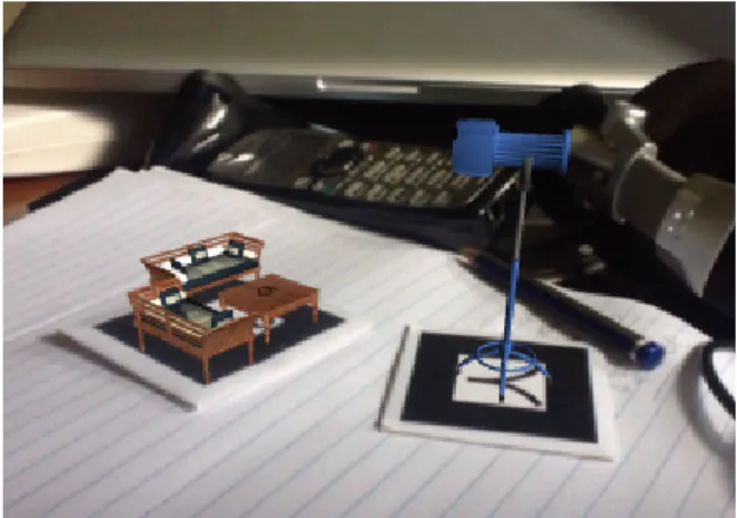
Marker based AR uses camera and visual marker to identify the content to be displayed. Once the marker is identified by the camera the AR software produces the 3D object on top of the marker to display the required information. Common marker based AR is QR code, which displays the information contained in the QR code. Another interesting marker based AR is identifying a custom code and build the graphics around it. This is widely used by the companies to advertise their products
Figure 1.6 –Example of a marker based augmented reality application
The important aspect of Marker-based AR is to detect the marker in the real environment. Marker can be a sign or image that a computer system can identify from a video image using pattern recognition or image processing methods. Additionally the marker's scale and pose of the camera are detected to augment the information which fits the current visual environment.
Good markers are easily detectable under all circumstances. The system should also be able to calculate the pose of the camera using the detected marker. Four known points are sufficient to calculate the pose of a camera uniquely and the simplest shape to acquire them is a square. In addition, the locations of the corner points are relatively robust, as they can be estimated as intersections of edge lines.
The basic marker detection procedure consists of the following steps: 0. Image acquisition
• acquisition of an intensity image. 1. Pre-processing
• undistortion
• line detection/line fitting
• detection of the corners of the marker.
2. Detection of potential markers and discard of obvious non-markers • fast rejection of obvious non-markers
• fast acceptance test for potential markers. 3. Identification and decoding of markers
• template matching (template markers) • decoding (data markers).
4. Calculation of the marker pose • estimation of marker pose
• iterative pose calculation for accurate pose.
1.2.1 Types of markers
There are various kinds of markers which are used in AR, the critical aspect of the marker is it should be unambiguous to detect by the computer vision. Markers are so often seen from oblique angle and in a less illuminated environment and it hard to detect them. Its is observed the Markers with thick borders are identified in most of the cases so most of the markers come with thick borders.
Template markers are black and white markers that have a simple image inside a
black border . The detection systems identifies the markers by comparing their segmented images with marker templates.
2D barcode markers contain black and white data cells and may contain a border
and other objects. Computer vision system detects the marker by samples the pixels from the calculated center of each cell, and then resolves the cell values using them.
Imperceptible markers are not perceived by the humans. The visual patterns are
invisible but the marker detection system can recognize them. One possibility is if devices operate on different wavelengths than visual light like infrared range. Image markers, Infrared markers and miniature markers are commonly used imperceptible merkers.
Its important to chose a marker which is ideal to the application being developed. For example if the marker has to be detected by long distance, it is advisable to use template markers with clear design. If the application should be able to read unforeseen data like URL, data markers are the must.
1.2.2 How to Augment
After detecting the marker the application has to display the visualization to enhance the human perception depending on the application. The rendering can be done in many different ways, For example, the system can best catch human attention with non-photorealistic rendering (NPR), where the augmentation is bright and distinctive from the background. In contrast, photorealistic rendering, where virtual elements are indistinguishable from real ones, enhances visual perception in applications where high quality visualization is required.
Figure 1.7 - Augmenting 3D objects with realistic visual lights and shadows
There are wide range of Marker based application available on smart phones. Product info can be visualized by reading a bar code, apps produce 3D imaging on the screen after reading a specialized marker. Interior designing apps for the house
which are becoming quite popular. Searching a book by its cover page is one of the AR app shows how marker based apps can be used in daily life substituting the traditional search carried out.
1.3
Markerless OR Layer based augmented reality
Unlike marker-based AR, markerless augmented reality considers the enter real environment to place the virtual objects over the real scene. The tracking is based on predefined objects which are found in the real environment and based on the detection algorithm, graphic overlays are augmented to the scene.
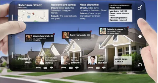
Marker-less OR layer based AR overlays a layer of information on top of the real camera scene with information like near by restaurants, underground metro line information, close by real estate properties or a AR game. This uses real world objects like photos,logos etc for augmentation. Once the target is identified a transformation between real world and virtual camera is estimated and virtual objects are rendered according to the estimation.
Important part of markerless AR is to identify where and how the graphical objects should be augmented to the real environment which is seen from the device. The resultant scene should be close to reality and enrich the user experience.
Processing of the real scene by the computer system can be done by processing the video frames using image processing or the scene can be identified by the Geo location . Apps like wikitude use the latter method to show the information about near by POIs. Where as applications like AR games use the combination of location info and image processing techniques.
1.3.1 How it works
The task of achieving markerless augmented reality is divided into three sub tasks. 1. Recognizing the overall context
2. Estimate transformation between real-world target and virtual camera. 3. Render virtual objects using estimated transformation.
The first step, finding the user’s overall position within a possibly large scene, need not be solved entirely based on visual information. Vision could be combined with GPS and this method is used in many modern day markerless applications.
The second step is often integrated with the first step. There are various ways to achieve the identification of visual patches which are critical for understanding the nature of the real environment and estimating the transformation between the target and virtual camera.
The techniques for marker less AR can be classified in two ways. Model based and
Structure from motion based (SfM). The model based AR uses a prior knowledge
of the real scene to identify the real world object. This method can not be used for unprepared scenario. In SfM based approaches, camera movement throughout the frames is estimated without any previous knowledge about the scene, which is acquired during tracking.
The Model based technique can be classified into three categories. Edge based, Optical flow based and Texture based. The first category consists in methods that take only the objects’ edges into consideration while doing tracking . The second one
relies on the optical flow of the image sequence, while the third one comprises the use of objects’ texture information to perform tracking.
Where as SfM based techniques are mainly online, since they do not require any previous offline learning phase. Due to this, it is possible to reconstruct a totally unknown environment on the fly. As a drawback, SfM approaches are often very complex. They also have some constraints related to their real-time nature.
To augment a scene with 2D objects users can chose a location for the visual textures. The visual textures move and scale in order to cope with viewpoint changes. The deformations and movements are calculated using affine transformations. Where as 3D objects can be augmented to a real scene by having the requirements of regions tracked being non-coplanar and they should be close to each other.
In order to use the natural scene patches as an alternative to artificial markers, affinely invariant regions are considered as markers. The affinely invariant regions are used to extract the same visual patch scene with the change in view point and illumination conditions. Invariant means, they cover they automatically deform their shape with changing view point as to keep on covering identical physical parts of the scene.
Figure 1.9 - Example of marker-less augmented reality
The local invariant regions can be distinguished based on a feature vector of moment invariants allowing them to be recognized on an individual basis. These regions are robust to track helping to obtain real-time performance. Once the affine transformation is completely retrieved tracking a single invariant region suffices for augmenting the scene with a virtual texture.
Below are couple of algorithms which are used in extracting the affine invariant regions .
Geometry based region extraction exploits corners and edges in the image yielding
parallelogram shaped regions .
Intensity based region extraction exploits the image intensity yielding elliptical
regions.
Once the affine regions are extracted from the they are matched with the preprocessed model view of the scene in case of model based technique. In the next step the patch from the natural scene is considered as a landmark and it is this patch tracked and replaced with virtual textures.
The important phase of the process is to augment the virtual objects on to the real scene. This can be achieved through 2D or 3D objects which overlay on the regions which are tracked and whose transformation is estimated frame by frame. As the shape of the patch or region changes depending on the view point even the
augmented objects are projected accordingly. Depending on the method used to extract the region and the motive of the application the virtual object is mapped on the screen seamlessly. The idea is to provide the user a seamless augmentation of the virtual objects with the real environment.
Another facet of marker less augmented reality is augmenting the graphical objects without extracting the visual patches. The region where the graphical object has to augmented is calculated by location and the direction at which the camera is pointed to. While the camera screen is displaying the captured frames, application maps the screen coordinates to the real environment in terms of latitude and longitude values. The application also knows the viewpoint and the magnetic field of the current location which is sufficient to map the screen coordinates to real world locations. An overlay will contain graphic objects which contains information about the real world locations which is projected on the screen.
The overlay objects seamlessly move according to the viewpoint, the objects which are associated with a real world location which is out of the view angle are discarded.
1.4
Augmented Vision
Augmented vision takes augmented reality applications to a hole new world. Augmented vision enabled devices come with built in display, camera, microphone, accelerometers, gyroscope, memory and processor. This is an incredible advancement in the field of augmented reality. Imagine what human sees with his bare eyes comes with an augmented layer which contains information about the things he is viewing. It takes voice commands from the user and acts as a personal assistant.
Figure 1.11 - Example of an augmented vision application
1.4.1 Google's project glass
Project google glass is one such device which brings a unique and enriching experience with its glasses. It comes with whole set of media devices which enable the user to see and hear the additional information processed by the device. The project which is still in developmental phase has generated immense curiosity. It is connected to the internet and fetches information on the go. User could get all sorts of information about the places, navigation or things he sees with just a voice command. It also comes with other features like reminding calendar events, public transportation information, information like weather and traffic which makes it truly
the next big thing in the field of augmented reality .
The project glass proof of concept has to meet many challenges before it can be a viable product. For true augmented reality, the display would have to dynamically focus, which would require additional hardware on the glasses to read one's eye. Bearing overlaid graphics that performs well indoors would be washed out when the user encounters the brightness of the outside world. Because of such huge differences in ambient light says creating a display that can handle multiple environments will be difficult.
Figure 1.12 – Google glass
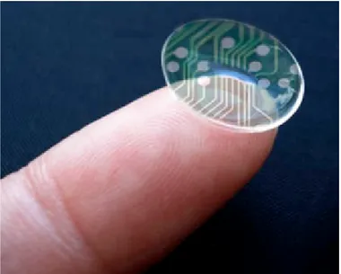
1.4.2 Augmented reality lens
The Center of Microsystems Technology (CMST), imec's associated laboratory at Ghent University (Belgium), has developed an innovative spherical curved LCD display, which can be embedded in contact lenses. The first step toward fully pixilated contact lens displays, this achievement has potential wide-spread applications in medical and cosmetic domains.
There are also other attempts of building the lens with LED and wirelessly powered with RF by University of Washington, which gives the hint of whats store in in future.
vision. By integrating communication circuits and miniature antennas into the lens using custom-built optoelectronic components it is possible to turn them into displays. Much of the hardware used is semi transparent and will not block the user's view. This technology is a potentially revolutionary idea in the field of augmented reality. The technology which augmented reality glasses posses will be made even personal to the user. But the technology is still in its early stages and will have to meet many challenges before it can be used for a fully functional augmented reality device.
Figure 1.13 – Augmented reality lens
Augmented reality devices come in various forms, they are used in various fields from educational to fun games which takes the virtual reality close to reality. Mobile phones will transform the technology to easy to use and accessible to the masses. In fact augmented reality applications are already creating ripples in the app market. The way in which information is fetched and perceived is changing rapidly. The future of augmented reality is very promising and
AR application for Polimi Leonardo campus
Aim of the thesis is to build a mobile application using the concepts of augmented reality discussed in the first chapter. Polimi AR is a marker less, location based mobile application targeted for the students of Polimi Leonardo campus. This chapter explains the underlying logic of the application.
2.1
Overview
The application is an attempt to help the students in finding the buildings and classrooms in Leonardo campus. As the Polimi Leonardo campus is spread across the area and contains many departments, it is quite a challenge for the new incoming students to find their classrooms. Although there exists a detailed Polimap which explains how to reach a certain location, an augmented reality solution would be really handy .
The application is built using augmented reality concepts with marker less OR layer based technique. It is a location based app which uses the current Geo location of the phone and find s the near by locations by running a query on sqlite database which contains the building information of the campus. This app intends to tag the buildings by their names and displays the classroom information which are present in the building.
The campus data is which is spatial data is stored in the SQLite database as spatial index data using the R-Tree algorithm. The location data is grouped according to their Minimum Bounding Rectangle (MBR) which makes it easy to fetch the spatial data depending on the current location. The query to the database will return the
The application runs on Android phones and needs the phone to have GPS and compass sensors. When the phone is pointed at a building (provided the app is running), an overlay layer will display the information about the building . If there are more than one buildings fall under the viewing angle of the phone's camera all the buildings are tagged corresponding information. When the Phone is moved along the axis the augmented information is displayed seamlessly.
There are three major tasks running simultaneously to ensure the augmented reality layer is displayed seamlessly to the user.
1. Gather the current location and Phone's pointed direction.
2. Find the POIs(point of interest) which are close to current location. 3. Map the POIs to the phone's screen (overlay layer)
Figure 2.2 - Screenshot-2 from the application
2.2
Getting location info and declination
The current application is location based, which means current Geo location of the user is the first and foremost thing to start the application working. The location information should contain Latitude and Longitude values and optionally Altitude. The device should have GPS sensor to read the current location.
Android SDK provides a service to know the current user location periodically. Once the application registers for the location service, Android location service makes sure that the change in Geo location is fed to the application periodically .
The Geo location will be supplied as Latitude, Longitude and Altitude values which are unique to any given location on the earth's surface.
The next step is to find the direction at which phone's camera is pointed. This is not a straight forward computation as there are many aspects to consider.
The parameters to consider before finding out the true direction of the phone's camera are as followed.
To know which direction the user has held the phone and the building information he is seeking, it is necessary to identify the direction in terms of traditional directions like North , South , East or West. Using geomagnetic field sensor and accelerometer to report a compass bearing with some additional calculations the direction can be known.
Figure 2.3 – geomagnetic field compensation
As earth's magnetic field is necessary to find the direction it is fetched from the magnetic field sensor. But before finding the magnetic field's north it is compulsory to find out the magnetic field at current location. Android's GeoMagneticField class provided with Latitude , Longitude, Altitude and timezone values returns the geomagnetic field value at the current location.
Using the known geomagnetic field it is possible to get the declination at the current location.
Figure 2.4 –Earth's Geo magnetic field intensity
Compute the
GeoMagneticField Compute the declination
Rotate around the x-axis
Magnetic declination is the angle between compass north (the direction the north
end of a compass needle points) and true north (the direction along the earth's surface towards the geographic North Pole). The declination is positive when the magnetic north is east of true north otherwise, negative.
The Geo magnetic field calculated is with respect to phone is parallel to the ground pointing to the sky, this has to be compensated by rotating the it around the x-axis, when working with the screen facing user's face in landscape mode.
Once the geo magnetic field is computed, using the Sensors ACCELEROMETER and MAGNETOMETER it is possible read the current acceleration and magnetic field strength which are needed to get the rotation matrix.
Rotation matrix Computes the inclination matrix I as well as the rotation matrix R transforming a vector from the device coordinate system to the world's coordinate system which is defined as a direct orthonormal basis, where:
• X is defined as the vector product Y. Z (It is tangential to the ground at the device's current location and roughly points East).
• Y is tangential to the ground at the device's current location and points towards the magnetic North Pole.
• Z points towards the sky and is perpendicular to the ground.
The rotation matrix which is obtained by Android API is in the vector form , convert it to a matrix form.
This matrix has to be be compensated to be compatible with true magnetic north . The matrix to rotate the geomagnetic field around x axis is given by
Figure 2.6 – Rotation matrix around x-axis
The final matrix obtained is compensated for the true north and now ready to be used in converting the latitude, longitude and altitude values to X, Y and Z coordinates to be mapped on the phone's screen.
2.3
Find the near by POIs
Every time location service notifies the application for a change in location, application has to make sure the near by locations are displayed in to the user. Application has to query the database which returns the near by POIs with respect to the current location.
Location data of Polimi Leonardo campus is stored in SQLite database in R-Tree spatial indexing format.
Figure 2.6 Spatial indexing using R-Tree
Around the user's current location a bounding box is selected and all the MBRs which intersect this bounding box are taken into consideration for displaying. The current location of user is the center point of the bounding box and a square around the point is calculated and is sent to the module which fetches the near by location. The current location is compared with the node in level 0 , which is the root. It contains a MBR which in turn covers all the child MBRs. If the bounding box around the current location intersects the MBR of the node then the search is carried out downwards along the children of that node. Search finally reaches the leaf nodes, if the leaf node's MBR which is the rectangle of the group it is added to the result. All the groups which intersect the search bounding box are considered as the POIs which have to be displayed on the screen. This provides a seamless transfer from one group of locations to another group of locations without any disturbances.
2.4
Mapping the POIs to Phone's screen
Phone's camera captures the real world and displays it on the screen. The location of the scene which is being seen from the camera is already computed by the previous steps. The location has been identified and near by POIs are fetched from the database.
Next step is to map the buildings by the corresponding data. Buildings should be tagged by their names and when the phone moves around in a 360 degree angle application should identify the POIs which fall in viewing angle and display the information. The information is displayed using 2D objects on a overlay layer.
Convert the latitude, longitude, and altitude of the POI into a relative x, y, z position. The x, y, and z fields are essentially the distance from the phones location to the POI in meters.
The vector now has the relative x, y, z location of Marker. Where z=latitude distance, x=longitude distance, and y=altitude distance.
The calculated x,y and z coordinates have to be compensated for phone's azimuth and pitch values where
Azimuth, angle between the magnetic north direction and the y-axis, around the
z-axis (0 to 359). 0=North, 90=East, 180=South, 270=West
Pitch, rotation around x-axis (-180 to 180), with positive values when the z-axis
moves toward the y-axis.
Figure 2.7- Phones coordinate
Compensate for the azimuth and pitch of the phone. This is done by setting a temp matrix with the relative x, y, z position (location XYZ relative to physical location) and the take the product of that matrix and the rotation matrix calculated earlier in the first step.
If he calculated x,y values are mapped to the screen coordinates, which is possible if the location is in the camera view then the POI data will be displayed. This information displayed is tagged to the real location which is being projected on the phone's screen. At any instance phone's screen might display n locations which fall in camera view.
Preparing the location data
Location data of the Polimi Leonardo campus available on Polimap is not suitable to use in the current application. Application runs without requiring a data connection (offline) requiring the location data to be present in the local storage. This chapter explains how the data is converted to a spatial index using the R-Tree algorithm.
3.1 Converting location data into Spatial indexing
If the location data is stored in normal relational database system without proper indexing is not an optimal solution as the query would take considerable amount of time to fetch the near by POIs . This problem is solved by using a R-Tree indexing method, which indexes the location data in a way which is easier to query and takes less time compared to traditional method.
Figure 3.1- Polimi Leonardo campus in Google maps
Chapter 3
Polimi Leonardo campus has more than 35 Edifice and they are all spread out around Citta studi, milano. The Edifice information with their names is populated in the location table of the local storage, in this case, SQLite.
Figure 3.2-Snippet of the Polimi Leonardo campus location data
It can be observed the data is populated without any order, it is not possible to group the rows by distance. It would take humungous effort to query all the POIs near a location. To overcome this problem R-Tree algorithm is used which indexes the spatial data in a convenient order.
To use the R-Tree algorithm efficiently the campus is divided into groups. The importance of grouping is explained in the later part of the section.
Figure 3.4-Grouping the locations
After building the R-Tree indexing for the location data the result is shown in the next figure.
Figure 3.5-Campus is divided into three regions (MBR) – R tree result
2 3 4 6 1 7 5
Figure 3.6-Leaf nodes of a MBR (original groups)
In the end the R-Tree indexed data is stored in the rtree table of the external storage which is queried during the course of the application.
Using the R-Tree indexing it is possible to query for the POIs which are inside a bounding box. For example it is possible to query for all the locations which are at a 500m distance from DEI . The R-tree indexing is efficient to return the results in a quick time by exploring the R-Tree.
Implementation of the Polimi AR application
Polimi AR is built using android SDK, using the various features android platform provides. This chapter describes the implementation details explaining how the android APIs are used in developing the augmented reality application.
4.1 Overview
Polimi AR application helps user to find the buildings and classroom information in Polimi Leonardo campus. Provided the application is running, application displays the building names for the buildings which are being displayed on the camera screen.
When the user moves the phone in 360 degree, the location information or POIs which are visible will be seamlessly displayed on the screen. User can chose to see a detailed information of a POI. A pop over will display the classrooms which the building hosts.
Another feature is to display the direction to a building. Application provides a search window to select the building to which user wants to know the direction to. User selects his choice building or POI and the application will display a arrow object which constantly points to the direction in which the building resides. This feature does not show the navigation, like the other GPS navigation applications, but it is a handy feature to know in which direction the user should walk to reach the place.
Figure 4.1-Screenshot from the polimi AR application
4.2 System requirements
The application is developed using Android SDK version 2.3.3 and minimum API level 10.
The application will run on all android powered phones which have the android operating system 2.3.3 or above.
Application is developed using Eclipse IDE .
4.3 Design considerations
This section contains all of the assumptions, dependencies, and constraints that were considered during the design of each subsystem and component.
4.3.1 Assumptions and dependencies
This application requires SQLite database support, where all the location data is stored and is constantly queried for the location data. Application assumes user has enough space on the external storage to hold the SQLite database which
The application assumes the phone has a camera and GPS powered. As the data is stored locally internet connection is not needed.
4.3.2 Constraints
Application will not run on phones which do not have camera and GPS support.
4.4 System architecture
Figure 4.2- system architecture
Magnetic field sensor SQLite Database
Accelerometer GPS sensor
The application uses the GPS data to know the current location , which is used to query the database for near by POIs. By using magnetic field sensor , the direction of the true north is computed and using accelerometer phone's direction is computed. Application handles all the sensor activities and displays the augmented reality information on the phone's screen.
4.5 Application block diagram
Figure 4.3- Application block diagram
4.5.1 AR Engine
AR engine is the core of the application, which takes the data from the sensor
AR Engine
Sensor service Sqlite
Overlay object Camera view
objects accordingly. It also makes sure the overlay object is augmented to the camera view. The sensor data has to be compensated for true magnetic north and phone's orientation.
Registering to get the location updates
Google API
public void requestLocationUpdates (String provider, long minTime, float minDistance, LocationListener listener)
Register the device to get accelerometer and magnetic field updates
Google API
public boolean registerListener (SensorEventListener listener, Sensor sensor, int rate)
Application has to register a call back to listen to the sensor events. Whenever there is a change in sensor readings which are in sync with user preference, the application is notified. If the latest readings differ from the previous sensor data, AR engine has to invoke the methods to apply the changes to augmented reality information which is being displayed.
Compensate for the magnetic field and phone orientation
The magnetic field values which are needed to find the true north direction to be used to find the direction at which the phone is pointing has to be compensated for its deviation from the true north. The current location's geomagnetic field field would provide the declination of the magnetic north from the true north . This is used to compensate for the true north.
Also the sensor data returned assumes phone is pointed to the sky, which also has to be compensated for.
Finding the near by POIs
When the sensor event for a change in location is received, the AR engine searches for the near by locations. If the user has not traveled a significant distance the POIs will remain the same. But it is known only by querying the data base which is
spatially indexed. SQLite helper API returns the nearest POIs to the current location which are then added to the overlay objects list .
The query will search all the locations which are within a distance of 500m from the current location. Around the current location a bounding box is calculated which has an area of 500 square meter and is sent to the SQLite helper API to find the near by POIs.
SQLite Helper API
getNearByPOI(float Latitude, float longitude, rect boundingBox)
The nearest POIs have to be displayed on the phone's screen. The overlay objects are updated accordingly.
POI direction
This feature points to the direction of the selected landmark. User can select a POI of his choice for which the application shows the direction. The application provides an interface to search for a POI by name and the selected POI will be added to graphical overlay. The overlay object will then display the direction to the POI according to user's current location and the phone's orientation.
Figure 4.5- Screen shot displaying the direction for a POI
4.5.2 Sensor Service
The sensor service handles the sensor data, updating current location, reporting accelerometer data and current magnetic field. It uses the android SDK APIs which provide the change in user location, change in orientation of the phone etc.
Android API provides a wrapper for the underlying sensors of the phone. The application which opts to use a particular sensor has to register for the same during the initialization.
Android location service
Android gives your applications access to the location services supported by the device through classes in the android.locationpackage. The central component of the location framework is the LocationManager system service, which provides APIs to determine location and bearing of the underlying device.
getSystemService(Context.LOCATION_SERVICE). The method returns a handle to a new LocationManager instance.
things:
•Query for the list of all LocationProviders for the last known user location.
•Register/unregister for periodic updates of the user's current location from a location provider (specified either by criteria or name).
•Register/unregister for a given Intent to be fired if the device comes within a given proximity (specified by radius in meters) of a given lat/long.
Android Accelerometer service
Once the application requests for the accelerometer readings using registerListener API android sensor service reports the change in accelerometer readings when there is a change in phone's orientation.
Sensor.TYPE_ACCELEROMETER reports the array of values : All values are in SI units (m/s^2)
values[0]: Acceleration minus Gx on the x-axis values[1]: Acceleration minus Gy on the y-axis values[2]: Acceleration minus Gz on the z-axis
Android Magnetic field service
Sensor.TYPE_MAGNETIC_FIELD reports the array of values
All values are in micro-Tesla (uT) and measure the ambient magnetic field in the X, Y and Z axis.
4.5.3 Sqlite database and helper class
The data storage which stores the location data and spatial index data from R-Tree. It provides APIs to query the data.
Location table
Figure 4.6- LOCATION TABLE
location table stores all the information about buildings, their Geo coordinates, name, information about the classrooms and the application specific group to which it belongs to.
The database helper class provides following APIs on the table
getLocations()
returns all the locations getLocations(List groupID)
returns all the locations belonging to the groupID
locationgroup table
The campus is divided into groups so that they can be efficiently queried from the Rtree spatial indexing. Each record contains a min and max values of the rectangle
in latitude and longitude values. This data is inserted into the R Tree .
Figure 4.7- LOCATIONGROUP TABLE The APIs provided by database helper are
getGroups()
returns all the records of the table
rtree table
Figure 4.8- RTREE TABLE
The rtree table contains the spatial indexing data which was prepared using the R-tree algorithm . This data is pre-configured and each record contains a node informaiton.
The minx, miny and dimx, dimy values hold the MBR information of the node. Node contains a pointer to its parent node, in case of root node this value will be zero. Non leaf nodes contain the pointer to its children (list of indexes) . Isleaf attribute is non zero if the node is a leaf otherwise its zero. If the node is a leaf it contains a pointer to groupid table .
Data helper provides the following APIs
Calculate the bounding box around the Latitude and Longitude (0.2Km square with current location as center point )
getNearbyPOIs(float lat, float long, rect boundingBox)
It takes the bounding box with current location at its center and returns the location groups which intersect the bounding box. This information is finally displayed on the screen.
4.5.4 Camera View
Camera view handles the camera and its view. It also provides the APIs to project points given the view.
To place an overlay one the camera application has to manage the preview size which is closest to the screen form factor. In common terms the preview size has to fit the screen. As different phones have different screen factors, it is necessary to identify the preview size the current device camera supports and use the values . The application handles the life cycle of the overlay view which is used to display the augmented reality objects. This view manages the camera operations like start and stop, and places the overlay view on top of the camera.
Another important thing to consider is the camera view angle which is set to 45 degree in this application. Camera view angle is used in projecting a point on the screen
Figure 4.9- Projecting a point to the camera screen
To determine which screen x-coordinate corresponds to a point at
A
x,A
z multiply thepoint coordinates by:
where
Bx is the screen x coordinate
A
x is the model x coordinateB
z is the focal length—the axial distance from the camera center to the image plane
4.5.5 Overlay object
With all the work in the background it is the job of overlay object to augment to the camera screen and display the information to the user. The objects move seamlessly according to the phone's movement, the objects are touch sensitive, they disappear when the POI is out of sight .
The over lay objects are bitmaps or drawing objects which are added to the camera surface view.
Figure 4.10- example overlay objects
When the application finds the near by POIs it creates an overlay object for each POI. It sets the name, details about the landmark and importantly the latitude and longitude values of the place. These values are never changed, overlay object uses the rotation matrix which has been computed by the AR engine and maps it to the screen.
Figure 4.11- Map the coordinates to the screen Create an overlay object Calculate the relative location Convert location to vector
Compensate the x,y,z for azimuth,pitch
of the phone Set location data
Take product of the
Conclusion
Augmented reality is an interesting field for the mobile space and it has a great future . As the mobiles are increasingly becoming an integral part of how we communicate, access the information Augmented reality applications are more relevant than ever . Mobile phones platforms have been improving their support to build a better augmented reality applications. The applications which are in the market now, could only be built in the research labs due to the expensive resources they required a decade back. The range of augmented reality applications currently in use are changing the way how one perceives the information. The technology has made augmented reality more realistic and easy to use.
The Polimi AR application is an attempt to recognize the trend and create an important tool for the students of Politecnico di Milano to connect with the campus. Specially for incoming students it is a very helpful tool to find the classrooms.
Most of the augmented reality applications work only with the data connection. Polimi AR app works offline, i,e , using the local storage. Currently mobiles phones platforms do not support the spatial database (there are few but are complex) which has brought in considerable amount of the data access speed than its predecessors . Polimi AR tries to emulate the spatial indexing by using R-Tree algorithm to index the location data .
The application has scope for further improvements . The application is scalable, the new modules can be introduced without much change in the existing platform .
1. Integrating data from social media, the application can augment the posts from students who are in the campus.
2. Extending the application for other olitecnico campuses by providing an interface for the user to update the locations.
3. Make the application work indoors, this needs more research about how to use the altitude information and WiFi signal strength inside a building.
4. Integrate with the language translator augmented reality tool to help the foreign students to understand the signboards.
5. Walking or driving directions inside the campus, which needs extensive data and querying techniques.
Appendix
6.1 R-Tree algorithm
R-tree is a height balanced tree which represents data in several dimensions. In this application two dimensional Geo data is used to represent the locations. The leaf nodes contain pointers to the data objects which contain the actual location. The structure of the R-tree is designed such that only few nodes are visited during the spatial search.
The spatial data is comprised of location data which is made of Latitude and Longitude values . The spatial data is grouped to form a minimum bounding
rectangle (MBR) which continues up to the root. The root comprises a MBR which covers all objects. The figure below explain a simple R-Tree structure
A B C m n k f g h t r
Chapter 6
structure of a simple R-tree
A, B and C are the root nodes. A, for instance, covers child nodes m, n and k and comprises them with a minimal bounding rectangle.
An R-Tree satisfies the following properties:
1. Every leaf node contains between m and M index records unless it is the root Thus, the root can have less entries than m
2. For each index record in a leaf node, I is the smallest rectangle OR a point that spatially contains the n-dimensional data object represented by the indicated tuple
3. Every non-leaf node has between m and M children unless it is the root 4. For each entry in a non-leaf node, i is the smallest rectangle that spatially
contains the rectangles in the child node or a spatial data point. 5. The root node has at least two children unless it is a leaf
6. All leaves appear on the same level. That means the tree is balanced
6.1.1 Structure of a leaf-node
Leaf nodes in an R-Tree contain index record entries of the form (I, tuple - identifier )
A B C
where tuple- identifier refers to a tuple in the database and I is an n-dimensional rectangle which is the bounding box of the spatial object indexed.
I = (I0, I1 ,..., In-1 )
In the current application tuple I points to a location which contains a spatial point.
6.1.2 Structure of a non-leaf node
The nodes which are no leafs contain entries of the form (I , child - pointer ) where child-pointer is the address of a lower node in the R-Tree and I covers all rectangles in the child node's entries.
6.1.3 Variable m and M
M is the maximum of entries which is usually given and m is the minimum of entries in one node.
Representation of M and m
The minimum number of entries in a node is dependent on M with M/2 >= m.
The maximum number of nodes is = N/m + N/m⌈ ⌉ ⌈ 2⌉ + ….+ 1 Here N stands for the
number
of index records of the R-Tree. m is jointly responsible for the height of an R-Tree and the speed of the algorithm.
a1 a2 M
6.1.4 Inserting locations in to R-Tree
Inserting index records for new data is similar to insertion into a B-Tree. New data is added to the leaves, nodes that overflow are split, and splits are propagated up the tree. The insertion algorithm is more complex than the searching algorithm because inserting needs some help methods.
6.1.5 Insert pseudo-code
New entry E will be inserted into a given R-Tree.
1. [Find position for new record] Start ChooseLeaf to select a leaf node L in which to place E
2. [Add record to leaf node] If node L has enough space for a new entry then add E. Else start SplitNode to obtain L and LL containing E and all the old entries of L.
3. [Propagate changes upward] Start AdjustTree on node L and if a split was performed then also passing LL.
4. [Grow tree taller] If node split propagation caused the root to split, create a new root whose children are the two resulting nodes.
6.1.6 ChooseLeaf pseudo-code
ChooseLeaf selects a leaf node to place a new entry E. 1. [Initialize] Set N to be the root node.
2. [Leaf check] If N is a leaf then return N.
3. [Choose subtree] If N is not a leaf node then let F be the entry in N whose MBR F:I needs least enlargement to include E:I. When there are more qualify entries in N, the entry with the rectangle of the smallest area is chosen.
F:p and repeat from 2
6.1.7 AdjustTree pseudo-code
Leaf node L is forwarded up to the root while adjusting covering rectangles. If necessary it comes to propagating node splits.
1. [Initialize] N is equal L.
2. [Check if done] stop if N is the root
3. [Adjust covering MBR in parent entry] P is the parent node of N and EN the entry of N in P. EN.I is adjusted so that all rectangles in N are tightly enclosed.
4. [Propagate node split upward] If N has a partner NN which was split previously then create a new entry with ENN:p pointing to NN and ENN.I enclosing all rectangles in NN. If there is room in P then add ENN. Otherwise start SplitNode to get P and PP which include ENN and all old entries of P.
5. [Move up to next level] N is equal L and if a split occurred then NN is equal PP. Repeat from AT2
Glossary
AR – Augmented reality VR – Virtual reality POI – Place of interest
MBR – Minimum bounding rectangles 2D – Two Dimensional
3D – Three Dimensional
GPS – Global positioning system HMD – Head mounted Display QR code – Quick response code NPR – Non photo-realistic rendering SfM – Structure from motion
LCD – Liquid crystal display LED – Light emitting diode
Bibliography
1. A Survey of Augmented Reality
Ronald T. Azuma,Hughes Research Laboratories,3011 Malibu Canyon Road, MS RL96,Malibu, CA 90265
2. Theory and applications of Marker-based augmented reality
Sanni Siltanen ,VTT
3. Markerless vision-based Augmented Reality for enhanced project visualization
Frédéric Bosché, David Tingdahl,Ludovico Carozza and Luc Van Gool
4. Markerless vision-based Augmented Reality for enhanced project visualization
David Tingdahl, Ludovico Carozza and Luc Van Gool, School of the Built Environment, Heriot-Watt University, Edinburgh, UK,ESAT/IBBT/VISICS, KU Leuven, Belgium,ARCES, University of Bologna, Italy,Computer Vision Lab, ETH Zurich, Switzerland
5. Proseminar: Algorithms and Datastructures for Database Systems R-Tree
Prof. A. Kemper, Ph. D, University of Passau
6. Augmented Reality http://prezi.com/p77w-kjjrjn_/augmented-reality/ 7. Markerless Augmented Reality with a Real-time Affine Region Tracker
V. Ferrari, T. Tuytelaars,and L. Van Gool,Computer Vision Group (BIWI), ETH Zuerich, Switzerland,ESAT-PSI, University of Leuven, Belgium
8. A Survey of Online Monocular Markerless Augmented Reality
Computer Science Center,Federal University of Pernambuco – Recife-PE
9. Planar Geometric Projections and Viewing Transformations
INGRID CARLBOM ,Program in Computer Science, Brown University, Providence, Rhode Island 02912 J JOSEPH PACIOREK ,Computervision Corporation, Bedford, Massachusetts 01730