UNIVERSITA’ DI PISA
Scuola di Dottorato in Ingegneria “Leonardo da Vinci”
Corso di Dottorato di Ricerca in
SICUREZZA NUCLEARE E INDUSTRIALE
Tesi di Dottorato di Ricerca
XXII Ciclo
NUCLEAR WASTE REDUCTION BY AN INTEGRATED
LWR-HTR-GCFR FUEL CYCLE
Autore:
ELEONORA BOMBONI
Tutori:
Prof. Ing. Nicola Cerullo
Prof. Ing. Giuseppe Forasassi
Dr. Ing. Guglielmo Lomonaco
SSD ING-IND/19
Ai miei genitori A Elena, Sara, Simona, amiche preziose
As far as the laws of mathematics refer to reality, they are not certain; and as far as they are certain, they do not refer to reality
Sommario
5
Sommario
Oggetto della presente tesi è un’analisi preliminare di un ciclo del combustibile innovativo orientato alla sostenibilità della produzione di energia per via nucleare, basato sui reattori avanzati di IV Generazione refrigerati ad elio: precisamente, il reattore a gas ad alta temperatura (High Temperature Gas Reactor - HTR o HTGR) ed il reattore a gas a spettro veloce (Gas-Cooled Fast Reactor, GCFR), combinati sulla base delle loro caratteristiche complementari. Il combustibile irraggiato dei reattori ad acqua leggera, come noto, è caratterizzato da un burn-up nucleare relativamente ridotto: pertanto, in virtù del suo elevato contenuto di elementi fissionabili (e, quindi, riciclabili come nuovo combustibile) nonché dell’elevata diffusione, nel presente e nel prossimo futuro, di tale tipologia di reattori, esso rappresenta il punto di partenza del ciclo proposto. Il reattore HTR, che grazie alle sue caratteristiche peculiari permette ampia flessibilità nella scelta del combustibile, può essere alimentato con il Nettunio ed il Plutonio provenienti dagli LWR, senza la necessità di aggiungere elementi fertili. L’irraggiamento nell’HTR riduce fortemente la massa di Nettunio e Plutonio e ne cambia profondamente la composizione isotopica, rendendola del tutto inadatta per scopi militari. Il Nettunio e il Plutonio stessi contenuti nel combustibile così bruciato, dopo essere stati separati chimicamente (senza separazioni isotopiche) dai prodotti di fissione e dagli attinidi minori (Americio e Curio), costituiscono il driver fuel per il GCFR, il cui core è costituito per la maggior parte da Uranio Depleto (DU). Si realizza in questo modo un ciclo capace di produrre energia a spese di materiale di scarto del ciclo dei reattori ad acqua leggera, riducendo così drasticamente la domanda di nuovo uranio da una parte e la massa di scorie da stoccare nei depositi dall’altra.
Per analizzare un ciclo siffatto si sono presi come riferimento rispettivamente il Pebble-Bed Modular Reactor 400 MWth (PBMR–400) come reattore a gas termico ed il reattore
GCFR “E” 2400 MWth come reattore a gas veloce (entrambi sono stati oggetto di studio
dei progetti PuMA e GCFR nell’ambito del VI Programma Quadro dell’UE). Il contenuto della tesi si può quindi riassumere nei punti seguenti:
1. I Capitoli 1 e 2 mostrano rispettivamente una panoramica sullo stato dell’arte in merito alle tecnologie di separazione e trasmutazione delle scorie nucleari, e in particolare degli attinidi (e alle relative problematiche aperte), le principali caratteristiche dei reattori avanzati refrigerati a elio e le loro potenzialità di raggiungere l’obiettivo di sostenibilità proposto dalla Generation IV Iniziative 2. I Capitoli 3÷5 mostrano le ipotesi, le sensibilità preliminari ed i principali calcoli
riguardanti l’analisi del ciclo integrato LWR-HTR-GCFR; sulla base dei risultati trovati vengono evidenziati i punti di forza e di debolezza non solo dei singoli concetti di nocciolo ma anche del ciclo nel suo insieme
3. Il Capitolo 6 è dedicato al progetto preliminare di un elemento di combustibile da inserire nel nocciolo del reattore GCFR e dedicato al bruciamento di Americio e Curio accumulatisi nel corso del ciclo, con l’obiettivo di minimizzare la quantità di elementi transplutonici da destinare ai depositi geologici
Sommario
Infine l’ultimo capitolo conclude l’analisi sottolineandone i principali elementi innovativi, in particolare per quanto riguarda la riduzione della massa e della radiotossicità delle scorie finali da stoccare, ed evidenziando anche i problemi aperti nonché gli elementi suscettibili di sviluppi futuri
Abstract
7
Abstract
The present work focuses on a preliminary analysis of an integrated nuclear fuel cycle involving Generation IV Helium-cooled reactors. Both the thermal and the fast concepts are considered here due to their complementary characteristics. The starting point of the analysis is the current Light Water Reactor (LWR) park, which supplies a huge amount of “fresh” fuel thanks to its relatively limited burn-up. The fertile-free core of the High Temperature gas-cooled Reactor (HTR) is the following step for Neptunium and Plutonium coming from LWRs. Successively, Neptunium and Plutonium irradiated in HTR act as a driver fuel for a Gas-Cooled Fast Reactor (GCFR) core containing high quantities of Depleted Uranium (DU). Americium and Curium coming from each reactor of this chain are inserted in some special (“dedicated”) assemblies and finally destroyed in the fast core itself.
Indeed, that “symbiotic” cycle basically aims at closing the current nuclear fuel cycle: in principle, thanks to the unique characteristics of Helium cooled reactors (thermal and fast), Light Water Reactor Spent Nuclear Fuel (LWR SNF) along with DU becomes valuable material to produce a lot of energy. Additionally, burning Heavy Metals (HM) coming from LWR waste means not only that the natural Uranium demand is drastically reduced, but also that the mass of the long-term radiotoxic component of nuclear waste is remarkably reduced.
In this framework, PBMR-400 and GCFR “E” 2400 (proposed in the EU 6th Framework PuMA and GCFR projects) have been respectively chosen as a HTR and a GCFR reference designs.
Then, the content of this thesis can be summarized as follows:
1. The first part (Chapters 1 and 2) shows the starting points of this study: the state of the art as far as the technology of Partitioning and Transmutation (P&T) is concerned with its main open issues; the main characteristics of advanced Generation IV He-cooled reactors and their capabilities to reach the goal of
sustainability
2. The second part (Chapters 3÷5) shows the hypotheses, the preliminary sensibilities, the main calculations and results regarding the integrated cycle proposed; on this basis, its strong and weak points are underlined
3. The third part (Chapter 6) addresses the preliminary design of an assembly for GCFR dedicated to burn Minor Actinides (MA) coming from the whole cycle. That aims at minimizing the HM amount in the final waste to store in geological repositories.
A final chapter concludes the analysis, underlining the major findings, particularly as far as the reduction of the waste amount and radiotoxicity is concerned. Finally, a critical review of the weak points of the proposed cycle and of the necessary developments is performed.
Table of Contents
Table of Contents
SOMMARIO ... 5 ABSTRACT ... 7 TABLE OF CONTENTS... 8 ABBREVIATIONS ... 10 LIST OF FIGURES ... 12 LIST OF TABLES ... 15 INTRODUCTION... 17CHAPTER 1 – CLOSING THE NUCLEAR FUEL CYCLE: AN IMPORTANT CHALLENGE FOR THE FUTURE NUCLEAR TECHNOLOGY ... 20
1.1 ADVANTAGES AND DRAWBACKS OF THE CURRENT LWR BASED NUCLEAR FUEL CYCLE ... 20
1.2 THE INNOVATIVE NUCLEAR REACTOR CONCEPTS: THE GENERATION IV INITIATIVE... 23
1.3 ADVANCED FUELS AND FUEL CYCLES: CHARACTERISTICS AND TECHNOLOGICAL CHALLENGES... 23
1.4 A BRIEF OVERVIEW OF THE STATE OF THE ART IN THE MATERIALS AND THE TECHNOLOGY OF PARTITIONING AND TRANSMUTATION (P&T)... 25
1.5 THE CONCEPT OF “SYMBIOTIC” FUEL CYCLE... 27
CHAPTER 2 – THE HELIUM COOLED ADVANCED REACTORS: MAIN CHARACTERISTICS AND POTENTIALITIES OF BURNING TRANSURANICS ELEMENTS... 31
2.1 THE HIGH TEMPERATURE GAS-COOLED REACTOR (HTR)... 31
2.2 THE GAS-COOLED FAST REACTOR (GCFR)... 35
CHAPTER 3 – THE LWR-HTR-GCFR SYMBIOTIC FUEL CYCLE ... 40
3.1 MOTIVATION, DESCRIPTION AND MAIN HYPOTHESES... 40
3.2 CODES AND LIBRARIES USED FOR THE LWR-HTR-GCFR CYCLE ANALYSIS... 41
3.3 PRELIMINARY ANALYSES... 43
CHAPTER 4 – THE PEBBLE-BED MODULAR REACTOR (PBMR) FUELLED WITH NEPTUNIUM AND PLUTONIUM FROM A TYPICAL LWR: CALCULATIONS AND RESULTS... 48
4.1 MODELS, CALCULATIONS AND RESULTS... 48
4.2 DISCUSSION OF THE RESULTS CONCERNING PBMR-400 IRRADIATION CYCLE AND MODELS... 54
Table of Contents
9 CHAPTER 5 – THE GAS-COOLED FAST REACTOR (GCFR) FUELLED WITH DEPLETED URANIUM AND NEPTUNIUM AND PLUTONIUM FROM
PBMR: CALCULATIONS AND RESULTS... 56
5.1 MODELS, CALCULATIONS AND RESULTS... 56
5.2 DISCUSSION... 62
5.3 LOMBT CALCULATIONS... 63
CHAPTER 6 – CLOSING THE CYCLE: DESIGN OF A DEDICATED FUEL ASSEMBLY TO BURN AMERICIUM AND CURIUM ... 69
6.1. ANALYSIS OF THE WASTE COMING FROM THE LWR-HTR-GCFR CYCLE... 69
6.2. HOW TO BURN AMERICIUM AND CURIUM MAIN ISOTOPES... 70
6.3. CHOICE OF THE MAIN CHARACTERISTICS OF A DEDICATED ASSEMBLY TO BURN AM AND CM –SURVEY CALCULATIONS... 73
6.3.1 Choice of materials ... 73
6.3.2 Assessment of the main parameters of the dedicated assembly ... 75
6.3.3 Survey calculations on a DA loaded with a IM-based fuel... 83
6.3.4 A good spectrum to burn Am and Cm ... 88
6.4. CHOICE OF THE MAIN PARAMETERS OF THE FINAL ASSEMBLY –CALCULATIONS AND RESULTS... 89
CONCLUSIONS ... 96
APPENDIX A – HEATLOAD OF THE FINAL WASTE OF THE LWR-HTR-GCFR SYMBIOTIC CYCLE ... 99
APPENDIX B – A QUICK REMINDER ON THE STATE OF THE ART ON THE KNOWLEDGE OF NUCLEAR CROSS SECTIONS OF ACTINIDES ... 104
APPENDIX C – SIMPLIFIED BALANCE CALCULATIONS CONCERNING THE LWR-HTR-GCFR CYCLE ... 106
REFERENCES... 114
Abbreviations
Abbreviations
ADS – Accelerator Driven System AFCI – Advanced Fuel Cycle Initiative An – Actinides
AVR – Arbeitsgemeinschaft VersuchsReaktor BCC – Body Centered Cubic
BG – Breeding Gain
BOC – Beginning Of Cycle BWR – Boiling Water Reactor
CANDU – CANada Deuterium Uranium CEA – Commissariat à l’Énergie Atomique CHPOP – Column Exagonal Point of Point CP – Coated Particle
DA – Dedicated Assembly DU – Depleted Uranium
EFPD – Effective Full Power Day EOC – End Of Cycle
EU – European Union FP – Fission Product FPY – Full Power Year FR – Fast Reactor
FTC – Fuel Temperature Coefficient GCFR – Gas-Cooled Fast Reactor GHG – GreenHouse Gases
GIF – Generation IV International Forum HM – Heavy Metals
HTR (or HTGR) – High Temperature gas-cooled Reactor IM – Inert Matrix
IMF – Inert Matrix Fuel LEU – Low Enriched Uranium LFR – Lead cooled Fast Reactor Ln – Lantanides
LOM – Level Of Mine
LOMBT – Level Of Mine Balancing Time MA – Minor Actinides
MC – Monte-Carlo MOX – Mixed Oxide MSR – Molten Salt Reactor NPP – Nuclear Power Plant OTTO – Once Through Then Out PBMR – Pebble Bed Modular Reactor P&T – Partitioning and Transmutation Pu-RG – Reactor-Grade Plutonium
Abbreviations
11 Pu-WG – Weapons-Grade Plutonium
PyC – Pyrolitic Carbon
PWR – Pressurized Water Reactor R&D – Research and Development SCWR – SuperCritical Water Reactor SF – Standard Fuel
SFR – Sodium cooled Fast Reactor SNF – Spent Nuclear Fuel
TRISO – TRiple ISOtropic Coated Particle TRU – TransUranics
VC – Void Coefficient
List of Figures
List of Figures
FIGURE 1–RADIOTOXICITY OF SNF VS. TIME...22
FIGURE 2–ESTIMATED INVENTORY OF MINOR ACTINIDES WORLDWIDE...27
FIGURE 3–EXAMPLES OF SYMBIOTIC FUEL CYCLES (1/2)...29
FIGURE 4–EXAMPLES OF SYMBIOTIC FUEL CYCLES (2/2)...30
FIGURE 5–HTR COATED PARTICLE STRUCTURE...32
FIGURE 6–PBMR CORE LAYOUT...33
FIGURE 7–GCFR2400MWTH“E” CORE...36
FIGURE 8–GCFR2400MWTH“E” FUEL ASSEMBLY GEOMETRIC PARAMETERS...38
FIGURE 9–HONEYCOMB STRUCTURE OF GCFR FUEL PLATES...38
FIGURE 10–SKETCH OF THE INTEGRATED LWR-HTR-GCFR FUEL CYCLE...41
FIGURE 11–MONTEBURNS WORKFLOW...42
FIGURE 12–SUMMARY OF THE PRELIMINARY ANALYSES PERFORMED...44
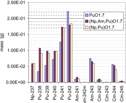
FIGURE 13–MASSES OF TRU NUCLIDES AT EOC FOR THE THREE INITIAL COMPOSITIONS IN HTR...45
FIGURE 14–MASSES OF TRU NUCLIDES AT EOC FOR THE THREE INITIAL COMPOSITIONS IN GCFR ...45
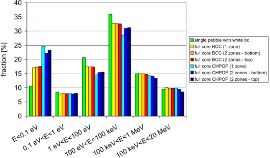
FIGURE 15–6-GROUPS SPECTRUM (%) AT BOC FOR THE DIFFERENT CORE MODELS...50
FIGURE 16–6-GROUPS SPECTRUM (%) AFTER 1062.50EFPD FOR THE DIFFERENT CORE MODELS...50
FIGURE 17– KEFF VS. BURN-UP FOR THE DIFFERENT CORE MODELS...51
FIGURE 18–PRODUCTION OF SOME LIGHT FPS PER INITIAL HM MASS IN THE DIFFERENT CORE MODELS (AFTER 1062.50EFPD)...51
FIGURE 19–PRODUCTION OF PU NUCLIDES PER INITIAL HM MASS IN THE DIFFERENT CORE MODELS (AFTER 1062.50EFPD)...52
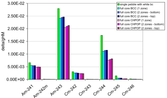
FIGURE 20–PRODUCTION OF AM AND CM NUCLIDES PER INITIAL HM MASS IN THE DIFFERENT CORE MODELS (AFTER 1062.50EFPD)...52
FIGURE 21–U NUCLIDES TREND IN THE PBMR CORE...53
FIGURE 22–PU NUCLIDES TREND IN THE PBMR CORE...54
FIGURE 23–MAIN MA NUCLIDES TREND IN THE PBMR CORE...54
FIGURE 24–SOME U NUCLIDES VS. IRRADIATION TIME IN GCFR...58
FIGURE 25–U238 VS. IRRADIATION TIME IN GCFR ...58
FIGURE 26–SOME PU NUCLIDES VS.IRRADIATION TIME IN GCFR...59
FIGURE 27–SOME MA NUCLIDES VS. IRRADIATION TIME IN GCFR ...59
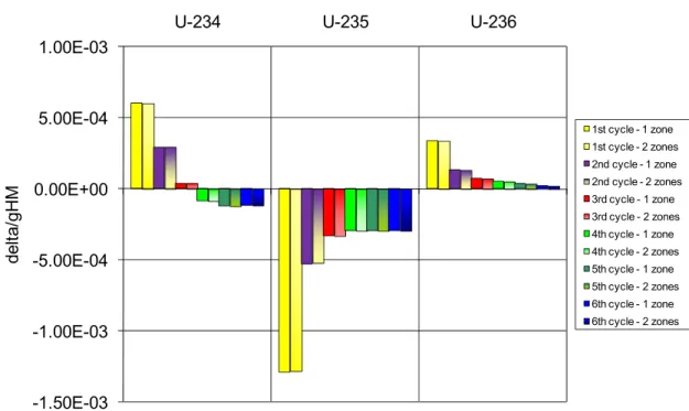
FIGURE 28–PRODUCTION/DESTRUCTION OF SOME U NUCLIDES PER INITIAL HM MASS IN THE DIFFERENT CORE MODELS, FOR EACH RECYCLE...60
FIGURE 29 –PRODUCTION/DESTRUCTION OF SOME NP AND PU NUCLIDES PER INITIAL HM MASS IN THE DIFFERENT CORE MODELS, FOR EACH RECYCLE...60
FIGURE 30 –PRODUCTION/DESTRUCTION OF SOME AM AND CM NUCLIDES PER INITIAL HM MASS IN THE DIFFERENT CORE MODELS, FOR EACH RECYCLE...61
FIGURE 31–LOMBT OF PBMRSNF(FPS,AM AND CM) ...65
FIGURE 32–LOMBT OF PBMRSNF(FPS,PU,MA) ...65
List of Figures
13
FIGURE 34–LOMBT OF GCFRSNF END 2ND CYCLE (FPS,AM AND CM)...65
FIGURE 35–LOMBT OF GCFRSNF END 3RD CYCLE (FPS,AM AND CM)...65
FIGURE 36–LOMBT OF GCFRSNF END 4TH CYCLE (FPS,AM AND CM) ...65
FIGURE 37–LOMBT OF GCFRSNF END 5TH CYCLE (FPS,AM AND CM) ...66
FIGURE 38–LOMBT OF GCFRSNF END 6TH CYCLE (FPS,AM AND CM) ...66
FIGURE 39–CONTRIBUTIONS TO RADIOTOXICITY VS. TIME –PBMRSNF(AM,CM AND FPS) ...66
FIGURE 40–CONTRIBUTIONS TO RADIOTOXICITY VS. TIME –GCFRSNF END 1ST CYCLE66 FIGURE 41–CONTRIBUTIONS TO RADIOTOXICITY VS. TIME –GCFRSNF END 2ND CYCLE ...66
FIGURE 42–CONTRIBUTIONS TO RADIOTOXICITY VS. TIME –GCFRSNF END 3RD CYCLE ...66
FIGURE 43–CONTRIBUTIONS TO RADIOTOXICITY VS. TIME –GCFRSNF END 4TH CYCLE ...67
FIGURE 44–CONTRIBUTIONS TO RADIOTOXICITY VS. TIME –GCFRSNF END 5TH CYCLE ...67
FIGURE 45–CONTRIBUTIONS TO RADIOTOXICITY VS. TIME –GCFRSNF END 6TH CYCLE ...67
FIGURE 46–CORRELATION BETWEEN DF AND FLUX FOR A ΣA FIXED: ΣA =1 BARN...71
FIGURE 47–CORRELATION BETWEEN DF AND FLUX FOR A ΣA FIXED: ΣA =10 BARN...72
FIGURE 48–CORRELATION BETWEEN DF AND FLUX FOR A ΣA FIXED: ΣA =100 BARN...72
FIGURE 49–THEORETICAL MODERATION RATIO NM/NF AS A FUNCTION OF THE HM MASS FOR THE IM FUEL AND THE STANDARD TRISO FUEL...76
FIGURE 50–REACTION RATE AS A FUNCTION OF THE HM MASS IN THE DA ...77
FIGURE 51–REACTION RATE AS A FUNCTION OF THE HM MASS IN THE DA–INERT MATRIX (IM) FUEL...78
FIGURE 52–REACTION RATE AS A FUNCTION OF THE HM MASS IN THE DA–STANDARD TRISOFUEL (SF) ...78
FIGURE 53–FLUENCE ON AM241 AS A FUNCTION OF THE HM MASS IN THE DA– COMPARISON BETWEEN IM AND SF...79
FIGURE 54–FLUENCE ON AM243 AS A FUNCTION OF THE HM MASS IN THE DA– COMPARISON BETWEEN IM AND SF...79
FIGURE 55–FLUENCE ON CM244 AS A FUNCTION OF THE HM MASS IN THE DA– COMPARISON BETWEEN IM AND SF...80
FIGURE 56–SPECTRUM AS A FUNCTION OF THE HM MASS IN THE DA–IM FUEL...81
FIGURE 57–SPECTRUM AS A FUNCTION OF THE HM MASS IN THE DA–STANDARD TRISO FUEL...81
FIGURE 58–SPECTRUM AS A FUNCTION OF THE HM MASS IN THE DA IN CENTRAL POSITION...82
FIGURE 59–SPECTRUM AS A FUNCTION OF THE HM MASS IN THE DA IN PERIPHERAL POSITION...82
FIGURE 60–AM241 MASS VS. BURN-UP...86
FIGURE 61–AM243 MASS VS. BURN-UP...86
FIGURE 62–CM244 MASS VS. BURN-UP...87
FIGURE 63–MODERATION RATIO IN THE DA AS A FUNCTION OF THE HM MASS AND OF THE COOLANT FRACTION...88
FIGURE 64–6-GROUP SPECTRUM AT BOC...89
FIGURE 65–X-Y VIEW OF GCFR“E”2400 MODEL WITH 13DAS IN THE CENTRE; EACH DA CONTAINS 6 KG OF (AM+CM) ...90
FIGURE 66–COMPARISON OF THE SPECTRUM IN THE FINAL CONFIGURATION WITH THE SPECTRA IN FIGURE 64 ...91
List of Figures
FIGURE 67–MASS OF THE DIFFERENT ELEMENTS IN THE DEDICATED FUEL AS A FUNCTION
OF BURN-UP...93
FIGURE 68–MASS OF THE DIFFERENT ISOTOPES IN THE DEDICATED FUEL AS A FUNCTION OF BURN-UP –THE SAME COLOUR INDICATES DIFFERENT NUCLIDES OF THE SAME ELEMENT...93
FIGURE 69– KEFF TREND COMPARISON –IMPACT OF THE PRESENCE OF 13DAS IN THE CORE ...94 FIGURE 70–6-GROUP CORE SPECTRUM –IMPACT OF DAS...94
FIGURE 71–CONTRIBUTIONS TO HEATLOAD VS.TIME –PBMRSNF(AM,CM AND FPS – BURN-UP 350GWD/THM) ...99
FIGURE 72–CONTRIBUTIONS TO HEATLOAD VS.TIME –GCFRSNF(AM,CM AND FPS) END FIRST CYCLE (BURN-UP 100GWD/THM) ...100
FIGURE 73–CONTRIBUTIONS TO HEATLOAD VS.TIME –GCFRSNF(AM,CM AND FPS) END SECOND CYCLE (BURN-UP 100GWD/THM)...100
FIGURE 74–CONTRIBUTIONS TO HEATLOAD VS.TIME –GCFRSNF(AM,CM AND FPS) END THIRD CYCLE (BURN-UP 100GWD/THM)...101
FIGURE 75–CONTRIBUTIONS TO HEATLOAD VS.TIME –GCFRSNF(AM,CM AND FPS) END FOURTH CYCLE (BURN-UP 100GWD/THM)...101
FIGURE 76–CONTRIBUTIONS TO HEATLOAD VS.TIME –GCFRSNF(AM,CM AND FPS) END FIFTH CYCLE (BURN-UP 100GWD/THM)...102
FIGURE 77–CONTRIBUTIONS TO HEATLOAD VS.TIME –GCFRSNF(AM,CM AND FPS) END SIXTH CYCLE (BURN-UP 100GWD/THM) ...102
List of Tables
15
List of Tables
TABLE 1–RATIOS OF URANIUM RESOURCES TO PRESENT (2006) ANNUAL CONSUMPTION
FOR DIFFERENT CATEGORIES OF RESOURCES, SHOWING THE IMPACT OF
RECYCLING IN FAST NEUTRON REACTORS (IN YEARS)...18
TABLE 2–LWRPU AND MA COMPOSITION (BURN-UP 33GWD/THM; INITIAL ENRICHMENT 3.2%U235;5 YEARS COOLING)...21
TABLE 3–DECAY POWER AND OTHER PROPERTIES OF SOME ACTINIDE NUCLIDES...22
TABLE 4–SUMMARY OF SOME ADVANCED PROCESSES FOR AN PARTITIONING...26
TABLE 5–MAJOR DESIGN AND OPERATING CHARACTERISTICS OF THE PBMR ...34
TABLE 6–FUEL ELEMENT CHARACTERISTICS...34
TABLE 7–MAIN CORE PARAMETERS OF GCFR2400MWTH“E”...36
TABLE 8–MAIN FUEL PLATE CHARACTERISTICS...39
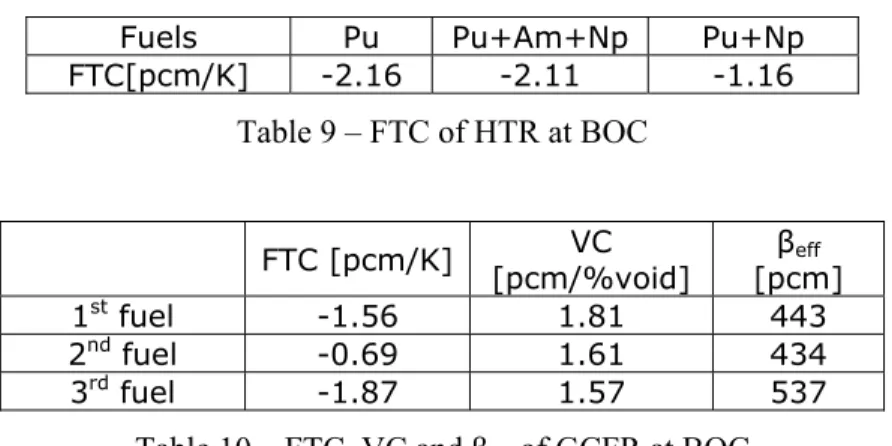
TABLE 9–FTC OF HTR AT BOC...46
TABLE 10–FTC,VC AND ΒEFF OF GCFR AT BOC...46
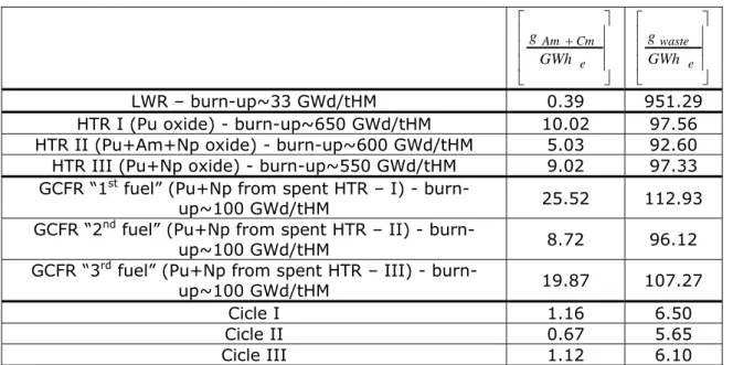
TABLE 11–MASS PRODUCED PER UNIT ENERGY FOR THE DIFFERENT KIND OF CORE AND FUEL COMPOSITIONS...46
TABLE 12–MASS OF WASTE PER UNIT ENERGY FOR THE DIFFERENT KIND OF CORE AND FOR THE PROPOSED SYMBIOTIC CYCLES...47
TABLE 13–CORE MODELS ANALYZED: MAIN CALCULATION PARAMETERS...49
TABLE 14–PBMRHM COMPOSITION AT BOC AND EOC(356GWD/THM)...53
TABLE 15–TEMPERATURES OF THE CONSIDERED CORE MODELS...56
TABLE 16–COMPOSITION OF GCFR FUEL AT THE BEGINNING OF EACH CYCLE CONSIDERED (EACH CYCLE CONSISTS OF 3162.50EFPD, I.E.100GWD/THM) –CYCLES 1–3 ...57
TABLE 17-COMPOSITION OF GCFR FUEL AT THE BEGINNING OF EACH CYCLE CONSIDERED (EACH CYCLE CONSISTS OF 3162.50EFPD, I.E.100GWD/THM) –CYCLES 4–6 ...57
TABLE 18–REACTIVITY PARAMETERS FOR THE 1-ZONE GCFR“E” CORE MODEL...61
TABLE 19-REACTIVITY PARAMETERS FOR THE 2-ZONE GCFR“E” CORE MODEL...62
TABLE 20–LOM FOR SNF OF THE CONSIDERED REACTORS...64
TABLE 21–WASTE PER UNIT ENERGY –COMPARISON...64
TABLE 22–TOTAL MASS OF AM AND CM AT THE END OF THE SYMBIOTIC CYCLE...69
TABLE 23–AVERAGE MASS FRACTIONS OF AM+CM WASTE COMING EACH YEAR FROM THE CYCLE...69
TABLE 24–EFFECTIVE 1-GROUP ABSORPTION CROSS SECTIONS OF THE MAIN AM AND CM ISOTOPES IN PBMR AND GCFR SPECTRUM...70
TABLE 25–AVERAGE FLUX INTENSITY IN PBMR-400 AND GCFR2400“E” ...70
TABLE 26–MA-BASED TRISO PARTICLE PROPOSED FOR THE DEDICATED ASSEMBLY....75
TABLE 27–MA-BASED TRISO PARTICLE WITH IM KERNEL PROPOSED FOR THE DEDICATED ASSEMBLY...75
TABLE 28–IMPACT OF 9DA WITH 9 KG OF HM ON THE CORE SAFETY PARAMETERS AS A FUNCTION OF DA POSITION –IM FUEL...83
List of Tables
TABLE 30–RESULTS OF BURN-UP CALCULATIONS CONCERNING AM243...84
TABLE 31–RESULTS OF BURN-UP CALCULATIONS CONCERNING CM244...84
TABLE 32–RESULTS OF BURN-UP CALCULATIONS CONCERNING THE TOTAL HM MASS..85
TABLE 33–REACTIVITY PARAMETERS –IMPACT OF 13DAS EACH CONTAINING 6 KG OF
MA, PLACED IN THE CENTRE OF THE CORE...92
TABLE 34–6TH IRRADIATION CYCLE –RESULTS FOR 13DAS EACH CONTAINING 6 KG OF
MA AT BOC, PLACED IN THE CENTRE OF THE CORE...92
TABLE 35–MAIN FUEL COMPOSITION (W/O)–IMPACT OF 13DAS IN THE CORE...92
TABLE 36–HEATLOAD AS A FUNCTION OF DECAY TIME FOR PBMR AND GCFR WASTE
...103 TABLE 37–AN EXAMPLE OF UNCERTAINTIES ON THE FISSION CROSS-SECTION OF TWO
MAIN CM ISOTOPES FOR SOME ENERGY RANGES OF INTEREST FOR SFR
TECHNOLOGY...104
TABLE 38–TARGET ACCURACIES FOR FAST NEUTRON SYSTEMS...104
TABLE 39–SUMMARY OF HIGHEST PRIORITY TARGET ACCURACIES FOR FAST REACTORS
...105 TABLE 40–HM COMPOSITION IN THE PBMR-400 MODEL –U,NP AND PU...108
TABLE 41–HM COMPOSITION IN THE PBMR-400 MODEL –AM,CM, OTHER NUCLIDES AND TOTAL HM ...108
TABLE 42–HM COMPOSITION IN THE GCFR-2400 MODEL –U,NP AND PU...109
TABLE 43–HM COMPOSITION IN THE GCFR MODEL –AM,CM, OTHER NUCLIDES AND TOTAL HM ...110
Introduction
17
Introduction
The need to cut greenhouse gas emissions (GHG) in an effort to tackle climate change has become a major driver of energy policy. Indeed, an “energy revolution” is needed to decarbonise energy supply, which is heavily reliant on fossil fuels. An important part of the scientific community believes that at least 50% of GHG emissions must be cut from 2005 levels by 2050, in order to limit the average temperature increase to 2-3ºC and to avoid the worst consequences of global warming [OECD/NEA, 2009].
As of 1 January 2010, a total of 436 commercial nuclear reactors are operating in 30 countries, with an installed electric net capacity of about 370 GWe,and 56 reactors with
an installed capacity of 51 GWe are under construction in 15 countries
[http://www.euronuclear.org]. That means, about 15% of the global energy production
is assured by nuclear power, which is the only energy source, along with hydro power, that is at present greenhouse-free and highly available at the same time. Furthermore, an other important peculiarity of nuclear energy is its fuel, Uranium (and, potentially, Thorium), which does not have any other significant application field beyond nuclear power production. In contrast, fossil fuels (oil, gas, etc.) are very valuable materials that constitute for example the basis for the most of the current and future chemical industry. Furthermore, as known [http://www.world-nuclear.org], the impact of the rough material on the final price of kWh is by far smaller for nuclear power than for fossil sources: just to set an example, 17% of the total kWh generation cost for EPRTM is expected to be fuel costs, and those broke down as 51% natural uranium, 3% conversion, 32% enrichment, and 14% fuel fabrication. The total fuel costs of a Nuclear Power Plant (NPP) are about a third of those for a coal-fired plant and between a quarter and a fifth of those for a gas combined-cycle plant. Finally, we should never forget that 1 g of Uranium produces the same energy of 1 ton of coal, and the same ratio remains true regarding waste production.
As of today, the worldwide experience in producing civil nuclear power is equal to 13948 Reactors-Years [http://www.world-nuclear.com]. It is undoubted that today the Light Water Reactor technology has reached a full maturity, particularly from the safety point of view. Almost all the reactors currently under construction, like EPRTM, belong to Generation III/III+, which represents a further improvement of previous technology (like “classical” PWR and BWR), particularly thanks to their stricter safety requirements.
At the moment, at least until nuclear fusion will not be available, only an extensive production of energy by nuclear fission can save the planet not only from excessive greenhouse emissions, but also from the risk of an excessive depletion of fossil resources. Hence, the Generation III/III+ LWR technology is the only one which could answer to the increasing energy demand at once, since hydro power has already almost reached its highest expansion. Indeed, world demand for electricity is expected to double from 2002 through 2030 to meet the needs of an increasing population and, above all, sustain the world economic growth and the improved population life quality of developing countries [OECD/NEA, 2008]. Furthermore, electricity represents only 16% of the total energy used worldwide [Hittner, 2007]: that means, for solving energy
Introduction
issues, substitutes to fossil fuel have to be found not only for electricity generation but also for other uses. Several alternative uses of nuclear energy have the potential to heighten its role worldwide [OECD/NEA, 2008], such as the desalination of seawater, heat production for industrial or residential purposes and ultimately, production of the
energetic vector hydrogen. Particularly, desalination and hydrogen production could
become significant application fields of nuclear energy: for example, producing hydrogen1 by nuclear power could make this alternative energy carrier available with significantly less (or, even, not at all) greenhouse gas emissions in comparison with current methods. Indeed, any electricity producing reactor can produce hydrogen through the process of electrolysis. Moreover, if an effective high temperature nuclear reactor technology were developed, the production of high temperature heat and of hydrogen with more efficient processes would be possible. Of course, if these plans came to fruition, they could significantly increase uranium requirements. Hence, if a
fully sustainable nuclear energy production is envisaged, the LWR technology is not the final solution. Without considering the low operating temperatures, which do not allow
for producing high temperature heat and realizing cycles with high efficiencies, the current LWR technology is characterized by two main drawbacks, which are intrinsically connected to each other: the relatively small capacity of exploitation of U resources and the production of relatively “large” amounts of waste remaining toxic for hundreds of thousands of years, to store in geological repositories. However, sufficient resources exist to support a significant growth in nuclear capacity for electricity generation in the long term. In fact identified resources are enough for over 80 years, considering 2006 uranium requirements [OECD/NEA, 2008]. Moving to advanced reactors and recycling fuel, they could increase the long-term availability of nuclear energy from hundreds to thousands of years [OECD/NEA, 2009] (see Table 1).
Known conventional
resources
Total conventional
resources With unconventional resources With present
reactor technology 100 300 700
With recycling
using fast reactors > 3000 > 9000 > 21000
Table 1 – Ratios of uranium resources to present (2006) annual consumption for different categories of resources, showing the impact of recycling in fast neutron reactors (in years)
In addition, thorium, which is 3 times more abundant than uranium in the earth’s crust
[http://www.world-nuclear.org], is also a potential source of nuclear fuel, if alternative
fuel cycles are developed and successfully introduced. Thus, in principle sufficient nuclear fuel resources exist to meet current and future energy demands.
In order to develop the full potential of nuclear energy production, considerable exploration, research and investments are required. That is the goal of the so-called
Generation IV Initiative [http://www.gen-4.org]. As known, the Generation IV Initiative, which started in 2002, proposes six reactor concepts (SFR, LFR, GCFR,
VHTR, SCLWR, MSR) that, if developed, would allow for a fully sustainable nuclear energy production. All these concepts have their strong and weak points, but they would compensate each other if combined in a symbiotic way, in order to realize close, proliferation resistant fuel cycles. In such “symbiotic” cycles, 100% of U resources are virtually exploited and high level waste produced are recycled as a fresh fuel. Of course,
Introduction
19 we should not forget that not only innovative reactors, but also Partitioning and Transmutation (P&T) technologies are a key point so as to reach this goal.
A great effort is requested to develop this new nuclear age, and these technologies will not be available before 2030 at least. Meanwhile, the LWR technology could effectively supply all the energy for the world needs, leaving a waste which is valuable material to feed tomorrow’s reactors.
The symbiotic LWR-HTR-GCFR cycle here proposed belongs to this framework: the choice of such a cycle is due to the successful past operating experience with the HTR technology as well as to the unique potentialities offered by Helium as coolant both for thermal and fast reactors. In agreement with the principles inspiring the Generation IV
Initiative, the combination of LWR, HTR and GCFR aims at realizing a cycle where
each concept can do what the others cannot, exploiting Uranium resources integrally and minimizing the amount and the long-term toxicity of the final waste to store in geological repositories. Another direct consequence of this kind of cycle is a strong proliferation resistance, since a deep burn-up is realized and only chemical separation of elements of irradiated fuel is envisaged.
Chapter 1 – Closing the nuclear fuel cycle: an important challenge for the future nuclear technology
Chapter 1 – Closing the nuclear fuel cycle:
an important challenge for the future nuclear
technology
1.1 Advantages
and
drawbacks
of the current LWR based
nuclear fuel cycle
Currently there are more than 400 power reactors running worldwide, supplying about 15% of the total electricity produced. Nuclear power is, as known, the only CO2-free
source that is capable to satisfy today’s increasing energy demand. Nuclear power, thanks to the well-proven LWR technology, is very reliable and safe. Although among power plants NPPs have by far the highest ratio between energy supplied and waste produced, actually waste is probably their major drawback. Indeed, nuclear waste contains elements that are dangerous for more than 100000 years; in addition, the natural resources of nuclear fuel are limitedly exploited by the LWR technology, because of both neutronic and technological reasons. It has been clear since the beginning of the nuclear age that the nuclear fuel availability could be substantially increased by the Fast Reactor (FR) technology, which is virtually capable of utilizing almost 100% of U from mine against ~1% of LWRs. Furthermore, fissioning the whole U amount extracted from mine means to reduce the long-term radiotoxicity of the final waste as well. Thus, in order to reach these two goals contemporarily (so realizing a “sustainable” nuclear power production), more kinds of reactor have to be used, linked each other in a “symbiotic” way (see Par. 1.5). As known, the discharge burnup of fuel elements depends on both nuclear and technological reasons, consequently it can be quite different for different kinds of reactor. Regarding LWR, the most widespread concept worldwide, it lies in the range between 30000 and 60000 MWd/tHM. That entails that the mass loaded into a “typical” LWR (electric output equal to 1 GWe and
efficiency around 33%) amounts to about 25/30 tons of Heavy Metals (HM) per Full Power Year (FPY) and is followed by the same discharge rate of spent fuel, of which a relatively important fraction is composed of TRansUranics (TRU). After about 3 years of permanence inside the reactor core, the spent fuel is transferred to cooling pools. Approximately 350 different nuclides (200 of which radioactive) were created during irradiation, with the following average composition:
− 94% U238,
− 1% U235 (hence, Spent Nuclear Fuel (SNF) is still enriched if compared
to Unat),
− 1% Pu,
− 0.1% Minor Actinides (MA), − 3 ÷ 4% Fission Products (FP).
As far as the isotopic composition of Pu and MA is concerned, it is shown in Table 2 [IAEA, 2007].
Chapter 1 – Closing the nuclear fuel cycle: an important challenge for the future nuclear technology
21
Isotope Quantity [g/t HM] Mass fraction [%]
Pu238 140 1.5 Pu239 5470 59.0 Pu240 2230 24.0 Pu241 956 10.3 Pu Pu242 486 5.2 Np237 437 51.6 Am241 296 35.0 Am243 83.8 9.9 Cm242 6.2 0.7 MA Cm244 24 2.8
Table 2 – LWR Pu and MA composition (burn-up 33 GWD/tHM; initial enrichment 3.2% U235; 5 years cooling)
FP dangerousness decays in few centuries, but Pu and MA are very long-living, even more than 100000 years. Then, it is of particular concern the approximately 1 wt% of SNF composed of Pu and MA isotopes; furthermore, it is important to remember that Pu recycling alone has a rather insignificant impact on long term radiotoxicity reduction [IAEA, 2009a]. Therefore, the management, the minimization of SNF quantity, and its safe disposal are key issues for the present and the future of nuclear energy. However, it is important to recognize that what is called “nuclear waste” is actually composed largely of recyclable material. In principle, all actinides are able to produce energy by fission, either directly or indirectly by transmutation into fissile nuclei by one or more neutronic captures. That means, ~96% of SNF is potentially recyclable, whereas only FPs are really “waste,” at least from the energy production point of view (indeed, some of them could be extracted and used, as an example, for technological or medical applications). At the moment, only Pu is partially recycled in some countries in Mixed Oxide (MOX) fuel for LWRs. MOX technology allows the possibility to double the current natural resource exploitation, which corresponds to ~1% with the Once Through Then Out (OTTO) cycle. However, an integral use of U resources can be achieved only with the FR technology. Indeed, the Generation IV Initiative, aiming at a sustainable nuclear power, proposes 6 reactor concepts, whose 3 are fast (see Par. 1.2). In addition, recycling all HM from SNF reduces the mass of the material to be stored in geological repositories and may also reduce its long-term radiotoxicity. This reduction will be very strong if the final waste is constituted of only light FPs (see Figure 1, [OECD/NEA, 2006a]): indeed, their radiotoxicity balances the reference level (the so-called Level Of
Mine, LOM2) in less than 500 years. Moreover, recycling HM entails high neutronic
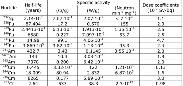
fluencies on them and, consequently, the build-up of MA and Pu nuclides with high mass number (240 or higher). That means, HM are made useless for military purposes3, because many of these heavier isotopes are characterized by both a high decay power and a high probability of self-fission (Table 3, [OECD/NEA, 2006a]).
2 The LOM corresponds to the radiotoxicity of that natural Uranium (U
nat) mass from which the
considered waste descends
3 In this connection, it is useful to remember that at least 93% of Pu-Weapons Grade (Pu-WG) is
composed of Pu239, because Pu-WG cannot contain more than 7% of Pu240 due to the relatively high
Chapter 1 – Closing the nuclear fuel cycle: an important challenge for the future nuclear technology
Figure 1 – Radiotoxicity of SNF vs. time
Specific activity Nuclide Half-life (years)
(Ci/g) (W/g) min(Neutron -1 mg-1)
Dose coefficients (10-7 Sv/Bq) 237Np 2.14·106 7.07·10-4 2.07·10-5 < 7·10-6 1.1 238Pu 87.404 17.2 0.570 155 2.3 239Pu 2.4413·104 6.13·10-2 1.913·10-3 1.35·10-3 2.5 240Pu 6580 0.227 7.097·10-3 53.7 2.5 241Pu 14.98 99.1 4.06·10-3 4.7 242Pu 3.869·105 3.82·10-3 1.13·10-4 95.3 2.4 241Am 432.7 3.43 0.1145 3.55·10-2 2.0 242mAm 144 10.3 3.08·10-2 1.9 243Am 7370 0.200 6.42·10-3 2.0 242Cm 0.445 3.32·103 122 1.21·106 0.13 244Cm 18.099 80.94 2.832 6.87·105 1.6 245Cm 8265 0.177 5.89·10-3 3.0 252Cf 2.64 537 38.3 2.3·1012 0.98
Chapter 1 – Closing the nuclear fuel cycle: an important challenge for the future nuclear technology
23
1.2 The innovative nuclear reactor concepts: the Generation
IV Initiative
Since the beginning of this century, a new interest in nuclear energy has increased as high capacity CO2-free energy source. Furthermore, there is a growing pressure from
society to reduce the amount of Pu stockpiles as well as of long-lived nuclear rest material as far as possible, and to further increase the safety of nuclear power stations. These points are addressed by the Generation IV Initiative. The Generation IV International Forum (GIF) is an international research initiative for the fourth generation of nuclear power plants, envisaged to enter service halfway the 21st century [US DOE, 2002]. Generation IV targets to improve all aspects of nuclear power generation: safety, economics, sustainability and availability. Six reactor concepts are considered, both thermal and fast, and almost all were studied in the past. The six reactor type are listed hereafter:
− VHTR: Very High Temperature Reactor − SCWR: Supercritical Water Reactor − GCFR: Gas Cooled Fast Reactor − SFR: Sodium cooled Fast Reactor − LFR: Lead cooled Fast Reactor − MSR: Molten Salt Reactor.
Each concept has its strong and weak points; if all (or at least some of) these concepts were used in a symbiotic system, they should counterbalance their mutual weak points. It is interesting to note that Generation IV is supported by other initiatives, like the Advanced Fuel Cycle Initiative (AFCI), in the effort of integrating all the aspects of nuclear power generation cycle, from U mining to waste storage. That means, not only the reactors, but also the whole fuel cycle (and then, the interconnections among reactors as well as among reactors, fabrication, reprocessing and disposal) are taken into account at the same time. This is a crucial point that makes Gen. IV technologies different from the past ones.
Thus, in the following paragraph we will have a look at the main aspects of advanced fuel cycles beyond the reactors themselves: fuels, partitioning and transmutation.
1.3 Advanced fuels and fuel cycles: characteristics and
technological challenges
As partially anticipated, closing the nuclear fuel cycle4 would permit the possibility to solve almost all the open issues regarding nuclear power, while assuring the energy supply worldwide for the future centuries. Of course, there are some challenging aspects at the moment as far as Partitioning and Transmutation (P&T) are concerned. Probably, the best way to close the nuclear fuel cycle would be an integral fuel cycle (as proposed for GCFR reactors [US DOE, 2002]). In such an approach, LWR SNF is reprocessed and its HM content represents part of the feed for a FR fleet. Hereafter, the spent fuel of FRs is reprocessed in situ, and all HM are recovered together (i.e. without separation of the different actinides) and reused to produce new fuel for the same FR fleet (multiple
homogeneous recycles), while FPs constitute the final waste. Such a strategy is at the
4I.e. all HM from mine are exploited to produce energy by fission, directly or indirectly by transmutation, then they are reprocessed and recycled; the final nuclear waste (virtually) consists of only (light) FPs
Chapter 1 – Closing the nuclear fuel cycle: an important challenge for the future nuclear technology
moment quite challenging, because a economically feasible process that allows for treating highly radioactive materials and for extracting HM with a very high efficiency (at least 99.9%) is needed. Moreover, treating not-negligible quantities of MA (particularly Cm, due to its strong γ and neutron emissions) seems to be quite difficult due to radioprotection problems, particularly in large facilities and along with large amounts of other HM. In addition, all the processes involved should be very effective as far as the separation of HM from FPs and the recoverability of reactants are concerned. Hence, recycling U, Pu and Np and, if appropriate, Am seems to be more feasible at the moment than recycling the whole group of HM. Np can be partitioned during the PUREX process, although this procedure has not yet been fully developed on an industrial scale. Regarding Cm, it seems to be advisable to store it temporarily, while waiting for its decay into Pu (the half-life of Cm244 is around 18 years). On the other hand, the separation of Cm from Am is quite challenging as well because of their similar chemical behavior. Then, storing Cm could entail storing Am together. However, Am and Cm could be recovered in some smaller dedicated facilities and reused in dedicated assemblies (heterogeneous recycle) for critical reactors or for Accelerator Driven Systems (ADS). In this connection, it is important to take into account that [Bomboni et al. 2009a]:
− Depending on neutron spectrum, recycling Cm entails the production of not-negligible quantities of Cf252, which is a very strong neutrons emitter (much stronger than Cm itself, Table 3) and, consequently, which is very difficult to be managed
− The opportunity of recycling Am without Cm has to be deeply assessed: indeed, it does not reduce the long–term radiotoxicity very much (not more than a factor 10 o less, due to the production of Cm from Am by neutron capture). That means, a challenging procedure of partitioning could eventually not be very effective from the long-term radiotoxicity reduction point of view
− In principle, building dedicated facilities for recycling Am and Cm could not be economical
As far as transmutation is concerned, a single reactor concept is probably not enough to burn HM effectively, but this purpose may be reached by chains of different reactors, each doing what the others are not able to do (see Par. 1.5). LWRs can be considered the starting point of all the possible chains, due to their current large diffusion worldwide, their proven technology and reliability as well as, last but not least, the large amounts of LWR SNF that are available worldwide. In addition, as shown above, LWR SNF is rich in fissionable elements. Nevertheless, it is not possible to burn HM completely in LWRs because of neutronic and technological reasons. Instead, HTRs and FRs have a larger flexibility from the point of view of the fuel choice. While HTRs can burn Pu as a fertile free fuel, FRs can exploit Pu by breeding U238, thus increasing largely the availability of nuclear fuel. Furthermore, the good neutron economy of the fast spectrum enables us to transmute even Pu isotopes and MA as well. Thorough analyses are requested in order to use new TRU-based fuels, particularly as far as the dynamic behavior of the core is concerned. In fact, the introduction of large fractions of Pu and MA tends to make worse safety parameters like the Fuel Temperature Coefficient (FTC) and the effective delayed neutrons fraction (βeff). Thus, it is advisable to design cores
with a very good neutron economy, which are able to reach and maintain the criticality also with small fractions of Pu.
Chapter 1 – Closing the nuclear fuel cycle: an important challenge for the future nuclear technology
25 After a quick overview of the state of the art in the P&T technology (Par. 1.4), on the basis of the considerations outlined up to now, the concept of symbiotic fuel cycle is presented at the end of this chapter. This foreword permits us to explain the background on which the idea of linking LWRs, (V)HTRs and GCFRs in a “symbiotic” way is based.
1.4 A brief overview of the state of the art in the materials and
the technology of partitioning and transmutation (P&T)
We are now aiming at summarizing just the main aspects of the very wide and complex issue of P&T, to focus on what is useful to know in the frame of the present study (we refer to the literature available for further information).
As far as the technology of advanced fuels for transmutation is concerned [Ogawa et al., 2005; Warin, 2008; IAEA 2009a], different options are currently considered. The main issue is the very different chemical behaviour of the different actinides. That entails that, at least in principle, the “classic” fuel forms like oxides, successfully used up to now for U- and (U,Pu)-based fuels, are not directly applicable to MA-bearing fuels. Furthermore, in order to obtain a high level of transmutation, the fuel should be irradiated up to very high burn-ups, then it should be particularly resistant to radiation damage. Key-points for the choice of a transmutation fuel are also the thermal conductivity and the density: carbides and nitrides are particularly favourable regarding these aspects, conversely carbides and nitrides of Am are volatile and then extremely difficult to treat, while carbides and nitrides of Cm are still poorly known [Somers, 2008]. An other important aspect to consider is the strong production of He in MA-based fuels due to the transmutation of Am241, which could cause too pronounced swelling rate. Thus, experiments were and are being carried out on (U,Pu,MA)- or MA-bearing oxides, nitrides [Arai et al., 2008], carbides [OECD/NEA, 2005], metals [Pasamehmetoglu, 2008], for thermal and fast reactors. Of course, the fuel form is dependent not only on the kind of reactor (thermal or fast), but also on the type of cycle (heterogeneous or homogeneous) and on the reprocessing envisaged as well.
When we are talking about transmutation fuels, an other interesting option to mention is the concept of fuel dispersed in a matrix: the Inert Matrix Fuel (IMF) consists of a neutron-transparent matrix (generally with good thermal conductivity) and a fissile phase that is either dissolved in the matrix or incorporated as macroscopic inclusions. The matrix plays the crucial role of diluting the fissile phase to the volumetric concentrations required by reactor control considerations, the same role U238 played in conventional low enriched uranium (LEU) or MOX fuel. The key difference is that replacing fertile U238 with a neutron-transparent matrix eliminates plutonium breeding as a result of neutron capture. A lot of different materials are potential candidates, among which oxides, but also metals, carbides and nitrides have been found to be acceptable in specific cases. Just as an example for the He-cooled high temperature reactor technology, two typical IM materials are silicon carbide (SiC) and Zirconia Stabilised Yttrium (ZRS) [IAEA, 2006], as we are going to see in the next chapters. Finally, an other important topic in the frame of transmutation is the concept of dedicated (partially moderated) assembly for burning MA in FRs: in order to exploit better the intense flux of FRs, introducing a MA-bearing fuel mixed with moderating material in certain zones of the core can maximise the transmutation rate of these nuclides. As far as the moderators are concerned, a lot of different materials have been considered for these dedicated assemblies: for example, hydrides are a particularly promising option, since they are very good moderators because of their H content.
Chapter 1 – Closing the nuclear fuel cycle: an important challenge for the future nuclear technology
However a not-negligible disadvantage is their relatively “low” (at least as far as He-cooled advanced reactors are concerned; see Ch. 2) operating temperatures (<800 °C, [Newton et al., 2003]).
As far as the reprocessing/partitioning technology of advanced fuels is concerned, a few processes have already developed at the laboratory scale obtaining the target efficiency (see Table 4 for some examples of processes developed in Europe [Warin and Boullis, 2008]). This is a very important point, since the feasibility of some options has been demonstrated, even though not at industrial scale yet. Indeed, we should keep in mind that, to have any significant impact on reducing the long term radiological toxicity of high level nuclear waste streams, minor actinide recovery requires an high efficiency – in the range of 99.9% [IAEA, 2009a]. Along with a few aqueous partitioning processes, pyrochemical ones are to be mentioned: indeed, they are a very attractive option for high burn-up fuels, since they are based on fuel dissolution in molten salts from which individual actinides are selectively precipitated by electrorefining. While aqueous processes are based on organic molecules that are scarcely resistant to radiolysis, molten salt are highly stable in all the possible conditions. Furthermore, whereas aqueous processes require mainly oxide fuels5, pyrochemical processes allow for treating each type of fuel form and for recovering virtually each kind of element. Nevertheless, they are currently characterized by low recovery efficiencies, very corrosive reagents, and high secondary losses [OECD/NEA, 2006b].
Process Aim Efficiency reached at the lab scale [%]
Advanced PUREX
Partitioning of Np, I, Tc (in addition to U and Pu, like in
the classic PUREX)
>99.9
DIAMEX Separation of (Am, Cm, Ln) from FPs >99.9
SANEX Separation of (Am, Cm) from Ln >99.9
SESAME Separation of Am from Cm >99.9 [Tuček, 2004]
GANEX6 Pu, Np, Am and Cm
co-extraction
>99.9 for U; experiments now running for Pu, Np, Am and Cm
in the ATLANTE facility Pyrochemical
processes extracted by electrorefining Each element could be Not available; generally low [Tuček, 2004]
Table 4 – Summary of some advanced processes for An partitioning
Before closing this short paragraph dedicated to these crucial technological aspects, it is interesting to show an estimate of the current and future inventory of actinides (Figure 2, [IAEA, 2009a]). As of the year 2006, it is estimated that about 110 tonnes of MA are contained in spent fuel storage worldwide, and other 40 tonnes are contained in high level waste products from reprocessing. In the absence of partitioning and transmutation, their amount will double by the year 2020 [IAEA, 2009a]
To conclude the present chapter, let us deepen a little the last “innovative” concept introduced by Gen. IV: the concept of “symbiotic” fuel cycle, object of the next paragraph.
5 If the fuel form is different (e.g. nitride or carbide), it is necessary to convert it into oxide before
reprocessing [Somers, 2008]
Chapter 1 – Closing the nuclear fuel cycle: an important challenge for the future nuclear technology
27
Figure 2 – Estimated inventory of minor actinides worldwide
1.5 The concept of “symbiotic” fuel cycle
As introduced above, a key concept of Gen. IV Initiative is a mixed nuclear fleet, where the different reactors counterbalance their mutual weak points, in order to obtain a fully sustainable nuclear energy production. That is particularly true as far as nuclear waste transmutation is concerned. A few different integrated cycles were proposed up to now7: generally, they are rather complex cycles, whose starting point is the current or the advanced (i.e. belonging to Gen. III/III+, like EPRTM) LWR fleet. The LWR SNF constitutes the “fresh” fuel for the innovative Gen. IV reactors. Each cycle has its advantages and drawbacks, and a fully satisfying (even if theoretical) solution has not been found yet. In addition, due to the extreme complexity of MA behavior from the core kinetics point of view, some integrated cycles also envisage a dedicated “sub-“part with ADS [OECD/NEA, 2006c]. Some additional examples are supplied in Figure 3 and Figure 4 [Van Der Durpel, 2008].
In this connection, it is interesting to briefly mention some observations of a study by NEA [OECD/NEA, 2006c]. Three kind of possible fuel cycles may be recognized:
a. Cycles based on the “current industrial technology and extensions”, where only LWRs and, if necessary, CANDUs are involved and only one recycle of HM is envisaged
b. “Partially closed fuel cycles”: these cycles are fully closed only for Pu; in some schemes a single recycle of some MA is envisaged in LWRs or FRs
c. “Fully closed fuel cycles”: all the advanced reactor concepts, ADS included, could be involved; only HM losses and FPs go to the geological repositories; pyrochemical reprocessing is envisaged
Hence, a key feature of the complete transmutation of HM underlined by this study is the following: in a full closed fuel cycle “all actinides are recycled continuously until
their fission”. That implies, a closed fuel cycle cannot be achieved without multiple
recycling of all HM.
Chapter 1 – Closing the nuclear fuel cycle: an important challenge for the future nuclear technology
Aim of the present work is to analyze an advanced fuel cycle, based on innovative He-cooled reactors, which may maximize the exploitation of natural resources, minimize the final mass and radiotoxicity of the waste and be proliferation resistant. Although longer and deeper analyses are still requested, it is possible to draw a first assessment highlighting the potentialities of a kind of symbiotic cycles based on two of the most promising Generation III+
/IV reactor concepts, i.e. (V)HTR and GCFR.
This cycle does not aim at being “the” solution: instead, it could be considered as an interesting, reasonably feasible possibility among the others, which could satisfy the exigencies of particular socio-political scenarios.
Chapter 1 – Closing the nuclear fuel cycle: an important challenge for the future nuclear technology 29 At-Reactor SF Centralised Interim SF Storage LWR-UOX LWR-UOX De-Centralised Interim SF Storage UOX Disposal Centralised Interim HLW Storage Reprocessing Aqueous Reprocessing LWR-MOX LWR-MOX MOX-Fabrication MOX UOX/MOX/CP-Fuel MOX (V)HTR (V)HTR CP-Fabrication CP-Fuel CP-Fuel UOX/M O X /CP-F u e l HLW Separated Pu/Np Storage Separated Am Storage Separated Cm Storage Advanced Aqueous Reprocessing At-Reactor SF Centralised Interim SF Storage LWR-UOX LWR-UOX De-Centralised Interim SF Storage UOX Disposal Centralised Interim HLW Storage Reprocessing Aqueous Reprocessing LWR-MOX LWR-MOX MOX-Fabrication MOX UOX/MOX/CP-Fuel/(S)FR-Fuel MOX (V)HTR (V)HTR CP-Fabrication CP-Fuel CP-Fuel U O X /M O X/ CP -Fue l HLW Separated Pu/Np Storage Separated Am Storage Separated Cm Storage Advanced Aqueous Reprocessing (S)FR (S)FR (S)FR-fuel Fabrication Group Separation
Chapter 1 – Closing the nuclear fuel cycle: an important challenge for the future nuclear technology At-Reactor SF Centralised Interim SF Storage LWR-UOX LWR-UOX De-Centralised Interim SF Storage UOX Disposal Centralised Interim HLW Storage Reprocessing Aqueous Reprocessing LWR-MOX LWR-MOX MOX-Fabrication MOX UOX MOX U O X /M O X/ CP -Fue l HLW Separated Pu/Np Storage Separated Am Storage Separated Cm Storage Advanced Aqueous Reprocessing (S)FR (S)FR (S)FR-fuel Fabrication Group Separation
Chapter 2 – The Helium cooled advanced reactors: main characteristics and potentialities of burning Transuranics elements
31
Chapter 2 – The Helium cooled advanced
reactors: main characteristics and
potentialities of burning Transuranics
elements
2.1 The High Temperature gas-cooled Reactor (HTR)
Developed since the middle of 1950s, the High Temperature gas-cooled Reactor (HTR or HTGR) is one of the most promising Gen. III+
/IV concepts. The peculiarities of this
kind of reactor can be summarized as follows [Bende, 1999]: − Fully ceramic core
− Helium as coolant (which is inert both from neutronic and chemical point of view; that makes possible a high-efficiency direct Brayton cycle)
− Semi-heterogeneous fuel, composed of tens of thousands of micro-spheres embedded in a matrix of graphite. That allows for a great flexibility as far as the fuel composition is concerned (see later)
− Graphite as moderator and reflector
− High thermal capacity and low power density (2÷3 kW/l) that make incidental transients very slow
− High surface-to-volume ratio of the coated particles in combination with the high heat conductivity of the graphite, which provides for an efficient heat transfer and a small temperature difference between the fuel kernels and the graphite matrix and, on the other hand, a small temperature difference between the centre of the fuel assembly and its surface. These small temperature differences enable relatively high overall fuel temperatures − High degree of passive safety, due to the combination of all these
characteristics
All these features allow for high operative temperatures (>800 °C), which make the plant global efficiency very high, particularly when the direct Brayton cycle is realized (in this case, the efficiency may be close to 0.50). Furthermore, the use of helium as coolant and of graphite as moderator and structural material entails reduced parasitic captures and then a very good neutron economy. Moderator separated from a neutronically inert coolant allows for changing the lattice parameters without changing dramatically the cooling conditions. As an example, if a loss of coolant occurs, the spectral shift is less important than in an LWR and the void coefficient remains negative. This implies a very large flexibility in the choice of the fuel and of the fuel cycle (e.g., in principle HTR can be loaded by Pu without fertile material [Bende, 1999]; an other interesting option is the possibility of using a Pu/Th fuel [Bomboni et al., 2008a],[Mazzini et al., 2009]).
Chapter 2 – The Helium cooled advanced reactors: main characteristics and potentialities of burning Transuranics elements
The key point of HTR is the fuel form. The fuel assemblies consist of cylindrical or spherical graphitic elements containing thousands of micro-particles of carbides or oxides of HM. The present work focuses on HTR loaded with spherical fuel elements: the so-called “pebble-bed” core. It is worth remembering that some important examples of HTR realized in the past are pebble-bed (e.g. the German AVR), as well as that the only HTR currently “scheduled to be first commercial scale HTR in the power
generation field” [http://www.pbmr.co.za], the Pebble Bed Modular Reactor (PBMR),
is a pebble-bed one as well.
The pebble-bed HTR is fuelled with graphite spherical fuel elements (Figure 5
[http://www.pbmr.co.za]) of 6 cm diameter. Within these pebbles one can distinguish a
fuel-free outer shell with a thickness of 0.5 cm and a fuel zone with a diameter of 5 cm in which tens of thousands of tiny coated fuel particles (CP) are embedded. The heart of such a coated particle is the fuel kernel, which has a diameter of 200÷500 µm, while the CP diameter can vary between 500÷1000 µm. The fuel kernel is surrounded by a few layers, each with a different function:
− A first layer of porous graphite, which provides the volume for the expansion of fission gases and volatile FPs,and attenuates fission recoils
− An inner layer of Pyrocarbon (PyC), which sets the substrate for the SiC layer
− A layer of SiC, which retains the gas and metal fission products and provides the mechanical resistance
− An outer PyC layer, which sets a bonding surface for compacting and acts as fission products barrier in particles with defective SiC
Figure 5 – HTR coated particle structure
Such a fuel element is a sort of miniature pressure vessel. The coatings of these particles provide for the retention of fission products up to very high temperatures (1600 °C). The cylindrical core of the pebble-bed reactor consists of a core cavity that is enclosed by axial graphite reflectors, at the bottom and the top, and by an annular cylindrical graphite reflector. The core cavity is filled with pebbles which constitute the actual pebble-bed (Figure 6 [de Haas and Kuijper, 2008]).
Previous studies showed that the pebble-bed HTR has great potential as a plutonium burner because of the following properties [Bomboni et al. 2008a; Bomboni et al., 2008b]:
Chapter 2 – The Helium cooled advanced reactors: main characteristics and potentialities of burning Transuranics elements
33 − Continuous refuelling, which enables the pebble-bed reactor to remain
critical without any large excess of reactivity at Beginning Of Cycle (BOC). This is realised by adding fresh pebbles on top of the pebble bed and/or by extracting irradiated ones from the bottom
− Ultra-high burn-up: coated particles dedicated to burning of plutonium were fabricated and tested in irradiation experiments up to 740 GWd/tHM [Rodriguez et al., 2002], that entails an incineration of about three quarters of the initial heavy metal content
− Moderation-ratio that can be easily varied by varying the number of CPs per pebble
.
Figure 6 – PBMR core layout
After this short overview of the unique features of HTR systems, let us have a look at the main parameters of the PBMR system proposed in the framework of the EU PuMA project [http://www.puma-project.eu], which will be the reference HTR system in the following of our study (Table 5 [de Haas and Kuijper, 2008]). As far as the fuel is concerned, the main pebble parameters are shown in Table 6 [de Haas and Kuijper, 2008].
Chapter 2 – The Helium cooled advanced reactors: main characteristics and potentialities of burning Transuranics elements
PBMR Characteristic Value
Installed thermal capacity 400 MWth
Installed electric capacity 165MWe
Core configuration Vertical with fixed centre graphite reflector
Fuel TRISO coated particles in graphite spheres
Primary coolant Helium
Primary coolant pressure 9MPa
Moderator Graphite
Core outlet temperature 900°C
Core inlet temperature 500°C
Total inlet He mass flow rate 192.7 kg/s
Equivalent core outer radius 1.85 m
Cylindrical height of the core 11.0 m
Total core volume 83.72 m3
Fixed central column graphite
reflector radius 1.0 m
Table 5 – Major Design and Operating Characteristics of the PBMR
Description Value Fuel pebble
Fuel pebble outer radius 3.0 cm
Thickness of fuel free zone 0.5 cm
Total heavy metal loading per fuel pebble 2.0 g
Matrix density 1.74 g/cm3
Packing fraction in pebble bed 61 %
Coated Particle
Kernel Coating Material C / C / SiC / C
Layer thickness 90 / 40 / 35 / 40 µm
Layer densities 1.05 / 1.90 / 3.18 / 1.90 g/cm3
Fuel kernel
Fuel kernel diameter 200 micron
Kernel material type PuO1.7
Pu-oxide density 10.89 (95% TD)
Table 6 – Fuel Element Characteristics
The capability of reaching ultra-high burn-ups, coupled with the possibility of using fertile-free fuels, makes the pebble-bed HTR a very good plutonium burner. However, a not-negligible production of higher MA (i.e. Am and Cm) is the major drawback of transmutation performed in this kind of core [Bomboni et al. 2008a; Bomboni et al., 2008b]. Thus, if we aim at reducing the LOMBT of the final waste, an other symbiotically coupled reactor is necessary to burn MA effectively. This task can be potentially performed by a GCFR, which is the subject of next paragraph.
Chapter 2 – The Helium cooled advanced reactors: main characteristics and potentialities of burning Transuranics elements
35
2.2 The Gas-Cooled Fast Reactor (GCFR)
As already explained in Ch. 1 and reminded in the former paragraph, the Gen. IV proposes new reactor concepts to reach a sustainable nuclear power production. Among the others, GCFR (which has already been studied in the early 1970s) is a particularly promising type. Incidentally, it is the only one for which a fully closed, all-FR cycle [OECD/NEA, 2006c] is envisaged. As known, the SFR is the concept that has reached the highest level of development among FRs up to now. Nevertheless, in comparison with sodium, gas coolants have advantages for fast reactor applications [van Rooijen, 2009]:
− Chemical compatibility with water, obviating the need of an intermediate coolant loop, and generally a good chemical compatibility with structural materials (if He is chosen as coolant, a full compatibility with all materials is obtained)
− Negligible activation of coolant
− Optically transparent, simplifying fuel shuffling operations and inspection. − Gas coolants cannot change phase in the core, reducing the potential of
reactivity swings under accidental conditions
− Strong reduction of the void worth in comparison with Sodium
− Harder neutron spectrum, which increases the breeding potential of the reactor
− Since gas coolants have a low number density, one can allow a larger coolant fraction in the core without an unacceptable increase in parasitic capture Of course, some disadvantages have made difficult the development of GCFR. All these disadvantages essentially derive from the very poor specific heat capacity of gases in comparison with liquid coolants, which entails:
− Necessity of artificial roughening of the cladding to maintain acceptable cladding temperature, resulting in an increased pressure drop over the core, and a higher requirement on pumping power
− Need to maintain high pressure in the system (for He-cooled systems, 7 MPa are needed)
− Higher pumping power compared to liquid coolants
− High coolant flow velocity, which can lead to significant vibrations of the fuel pins
− Difficulty of extracting the decay heat from an high power density core, particularly following a depressurisation event (this is a key point in the framework of the passive safety features of Gen. IV systems)
Nevertheless, GCFR is a very interesting option, particularly as far as the He-cooled one is concerned. Like for thermal HTR, in principle Helium allows for realising a direct Brayton cycle with high efficiency (about 50%). The He outlet temperature is around 850 °C, then the core has to be completely ceramic. As a backup option, an indirect cycle is envisaged: for this design, a secondary circuit with supercritical CO2 (25 MPa,
650 °C) is envisaged, realizing a cycle with a similar efficiency [van Rooijen, 2009]. In this study, the plate-type GCFR 2400 MWth “E” proposed by CEA is considered
[Richard et al., 2006], since it is the most recent and perhaps the most promising among the others. It is however to remember that at the time of writing no definitive
Chapter 2 – The Helium cooled advanced reactors: main characteristics and potentialities of burning Transuranics elements
configuration has been fixed for the GCFR core design, and a few different concepts are under study (e.g. the pin-type core).
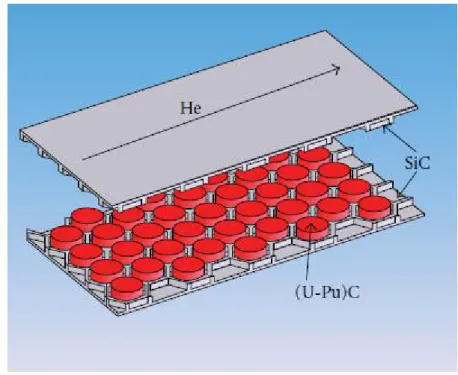
Thus, let us have a look at the main design parameters of the plate-type GCFR in Table 7 [Richard et al. 2006; Girardin et al., 2006]; a core layout overview is supplied in Figure 7 [Girardin et al., 2006]; the geometry of a typical fuel assembly is shown in Figure 8 [Richard et al. 2006], while the main fuel plate characteristics are in Table 8 [Richard et al. 2006].
Thermal Power [MWth] 2400
Power density [kW/l] 100
Specific Power [W/gHM] 40
Height/Diameter (H/D) ratio 0.63
Theoretical Breeding Gain 0.0
Fissile Height [mm] 2300
N° Fuel assemblies 162+120
N° Control rods 24
N° Reflector assemblies (Mixture of Zr3Si2, SiC
and He) 168
Nominal Coolant Pressure [MPa] 7.0
Helium inlet temperature [°C] 480
Helium outlet temperature [°C] 850
Maximum clad temperature [°C] 985
Maximum fuel temperature [°C] 1860
Coolant volumetric fraction [%] 30.8
Structural material volumetric fraction [%] 20.8
Helium pressure drop through the core [bar] 1.6
Average coolant speed through the core [m/s] 85
Table 7 – Main core parameters of GCFR 2400 MWth “E”