Supporting freight operators decision on investing in technology for rolling stock L.Cantone1, F. De Maria2, A. Palazzolo3, D. Negretti1
1
Università di Roma “Tor Vergata”, Dipartimento di Ingegneria Meccanica, via del Politecnico, 1 – 00133 Roma
2
Faiveley Transport Italia S.p.A.
3
TRENITALIA S.p.A., Direzione Tecnica – Ingegneria Rotabili e Tecnologie di Base, V.le Spartaco Lavagnini 58, 50129 Firenze
1 Introduction
Whilst on the AAR (Association of American Railroads) market the freight train already evolved embarking electronics for smarter power and braking control, European railways still rely on the UIC pneumatic brake system and manual buffers and draw gears. Nevertheless, thanks to the need to increase the railway freight capacity, the climate is good for the introduction of already available technologies like centre couplers (blocked or automatic), distributed traction and brake control and, as a consequence, the chance to increase the braking performance of rolling stocks.
The above mentioned technologies are considered fundamental in order to increase the capacity of railway freight transport achieved through the extension of the train length and mass, the increment of its speed and the reduction of idle times. However, according to their configuration and the train composition, these measures have an impact on the longitudinal dynamics that is in turn a parameter for ensuring running safety.
This research therefore presents the reference case of a European, conventional freight train on which certain driving manoeuvres are applied. Starting from the reference case, a number of possible new scenarios have been established. Each scenario is a combination of technologies applied on the train (for example the kind of coupling, the brake power and control) and its configuration (for example the number and the position of locomotives and the distribution of the freight mass). The trains related to the reference case and to each new scenario have been modelled and a longitudinal dynamic simulation has been run, using the TrainDy software1, according to different operational parameters. The simulation results can be compared in order to know how the new scenarios improve the running safety by reducing the longitudinal forces.
The outcome of this research, together with the operational model (for example blocked trains on fixed routes or single wagon) and integrated by business models (out of the scope of this research), enables freight operators to decide to invest on one, more or all the technologies according to the result of a rational cost/benefit analysis.
The mathematical models used in the TrainDy software are described in [1] and the validation of the software can be found in [2]-[4].
2 The reference case
This paragraph presents the reference case as a combination of a train configuration and the manoeuvres applied to it. The longitudinal forces exchanged between two following vehicles results from the simulation carried out with the TrainDy software. Positive values of the forces indicate a force slackening the train, negative values indicate forces tightening the train.
Table 1 reports the main data of the wagon and of the locomotive used to assembly the trains investigated in this paper, whereas Fig. 1 displays the diagrams of force-displacement characteristics for draw gears (a) and buffers (b).
Table 1 Main data of wagon and locomotive
Wagon length over buffers 21.78 m
Locomotive length over buffers 18 m
Brake pipe wagon length 22.87 m
1
Developed by Faiveley Transport Italia in collaboration with the University of Rome “Tor Vergata” and now owned, improved and certified by UIC.
Challenge C: Increasing freight capacity and services
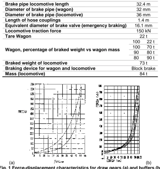
Brake pipe locomotive length 32.4 m
Diameter of brake pipe (wagon) 32 mm
Diameter of brake pipe (locomotive) 36 mm
Length of hose couplings 1.4 m
Equivalent diameter of brake valve (emergency braking) 16.1 mm
Locomotive traction force 150 kN
Tare Wagon 22 t
Wagon, percentage of braked weight vs wagon mass
100 22 t 100 70 t 90 80 t 80 90 t
Braked weight of locomotive 73 t
Braking device for wagon and locomotive Block brake
Mass (locomotive) 84 t
(a) (b)
Fig. 1 Force-displacement characteristics for draw gears (a) and buffers (b)
As reference case, it is considered a train set with one master locomotive and 18 wagons, resulting in an overall length of around 400 m. This train set has been chosen since it is typical of freight train transportation in Italy. Three levels of mass hauled are considered: Empty (E, all vehicles are empty), Half (H, all vehicles carry the half load) and Full (F, all vehicles carry the full load); of course, the uniform distribution of carried load is not representative of the general case, but it is here considered in order to have a first overview of the benefits offered by the different braking technologies and coupling equipments. The Empty case is here reported simply in order to pick out a linear or non-linear dependency of the longitudinal dynamics (expressed in terms of maximum longitudinal forces) as function of mass hauled.
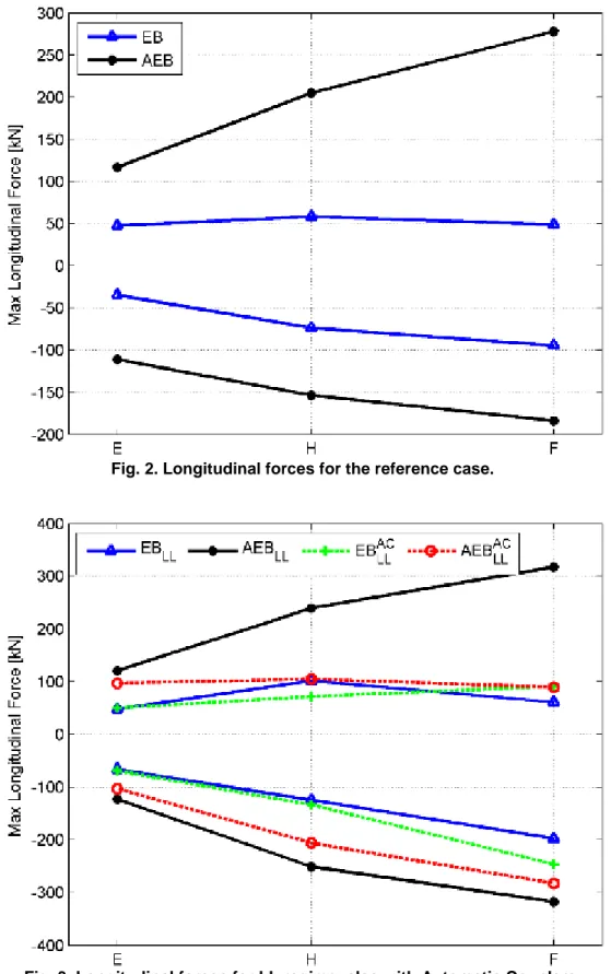
Two manoeuvres are considered in this paper: i) the emergency braking from 30 km/h (hereafter indicated as EB); ii) the emergency braking after the traction application that accelerates the train up to 30 km/h (hereafter indicated as AEB); these train operations have been chosen since they are usually considered as the most critical from the safety point of view. The braking regime chosen for the locomotive is G (goods) whereas the braking regime chosen from the wagons is P (passengers): this strategy of braking is typical and it aims to reduce the longitudinal compressive forces that may cause a derailment if they are experimented on a curve and/or between one or two empty vehicles.
Fig. 2 shows the maximum longitudinal forces (LF) for the reference case. It is clear that the emergency braking, after the train acceleration, enhances the longitudinal dynamics much more than the simple emergency braking: this is a general behaviour, even if the specific values, of the tensile and compressive longitudinal forces, change according to the characteristics of the traction unit. The evolution of the LF with the carried load is almost linear, in this case, for all considered tests: by increasing the hauled load the LF increase as well.
Fig. 2. Longitudinal forces for the reference case.
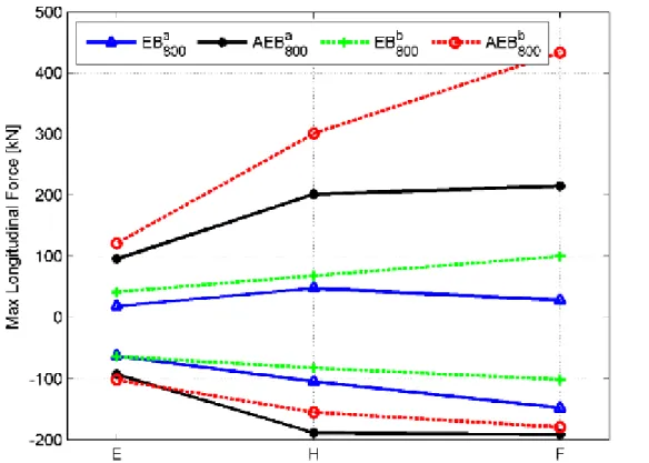
Fig. 3. Longitudinal forces for LL regime, also with Automatic Couplers.
In order to increase the carried load of the train using the common circulating wagons, it is a common practice setting the first locomotive and the 5 following wagons in braking regime G and the remaining wagons in braking regime P; this braking practice is called Long Locomotive braking regime (LL) and it has been recently approved also in Italy. Fig. 3 shows the longitudinal forces for such trains, whose lengths have been increased up to 600 m (carrying roughly 50% more than the reference case). By comparing the values of LF with the counterpart of Fig. 2, it is clear that the regime LL lets an increment of mass hauled but with an increment of the LF values, especially for the emergency braking that follows the train acceleration. This means that, in order to move to the LL regime, from the reference case, it is necessary to further investigate
Challenge C: Increasing freight capacity and services
the maximum permissible LF of the train set. Fig. 2 also shows the LF when the Automatic Couplers (AC) are used instead of the usual buffers/draw gears: the equipment of the vehicles with this technology provides a reduction of LF levels, especially for tension longitudinal forces.
3 The new scenarios
Aiming to further increase the hauled load, it is now considered a train equipped with two active and synchronized locomotives (i.e. both locomotives acting on the brake pipe and set to braking regime P), whose length is around 800 m (the hauled load is roughly two times more than the reference case). A typical question to address when there are two active locomotives distributed along the train is where to place the second (remote) locomotive; here this issue is not addressed systematically, but two cases are considered: a) the remote locomotive is in the middle of the train and b) the remote locomotive is placed at the end of the train. In general, the best placement of the remote locomotive (in terms of longitudinal forces) mainly depends on the mass distribution of the train. By comparing Fig. 4 with Fig. 3 and Fig. 2, it is clear that a train set with distributed brake pipe control (and traction) results in longitudinal forces (both tensile and compressive) comparable with the reference case, even if it carries the double load. Results show that it is preferable to place the remote locomotive in the middle of the train rather than at its end, especially if the attention is focused on the tensile longitudinal forces occurring during the emergency braking that follows the train acceleration.
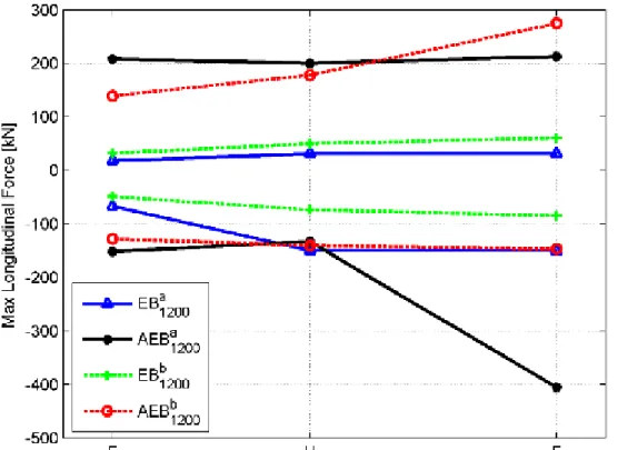
Fig. 5 shows the maximum longitudinal forces occurring in a train whose length is 1200 m and moved by three active and synchronized locomotives. In Fig. 5, it is indicated with “a” the train set made by the connection of three trains like the one of the reference case with the three locomotives placed at the head of the train and braking in regime P), whereas in the case “b”, the second locomotive is placed in the middle of the train and the third at its end. Fig. 5 shows that the placement of the remote locomotives is more important than in the case of only one remote locomotive, especially if the attention is focused on the emergency braking that follows the train acceleration and the train is heavily loaded. Among the different technologies considered until now, the results here reported confirm that the usage of remote locomotive is an effective practice for heavily loaded trains, resulting in longitudinal forces comparable with those of a train that carries a third of its load.
Fig. 5 Longitudinal forces for train of 1200 m length and two placements of the remote locomotives.
Fig. 6 Longitudinal forces for several train lengths and placements of remote locomotives, when all vehicles are braking.
Of course the synchronization between the locomotives is critical; in case of communication problems, missing or delayed braking, by the remote locomotives, has the potential consequence of a dangerous increase of the longitudinal forces.
The last technology here considered to increase the mass hauled is distributed braking that is having electro-pneumatic devices, at each wagon, for local brake under the control of the head locomotive. Fig. 6 refers to the case where all the vehicles brake at the same time, after removal of the traction. It is considered only this case since the previous results have shown that it is the most critical for the longitudinal dynamics. Results reported in Fig. 6 refer to trains of 800 m and 1200 m length, with the previously defined placements for the
Challenge C: Increasing freight capacity and services
remote locomotives. Comparing the results of Fig. 6 and of Fig. 5, especially focusing the attention on the 1200 m train, it is evident that braking all vehicles give a considerable reduction of the longitudinal dynamics (also respect to the reference case).
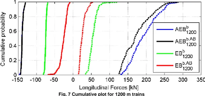
Fig. 7 Cumulative plot for 1200 m trains
Finally, a statistical analysis has been carried out considering the 1200 m train with the locomotives placed at the train head, in the middle and at the end, randomly changing the mass of the wagons; the same analysis has been carried on considering the wagons equipped with the electro-pneumatic brake: in this second analysis, vehicles masses are the same of the previous analysis, in order to emphasize the benefits of the newer technology. The results, in terms of cumulative probability vs. longitudinal forces, are reported in Fig. 7. The statistical analysis confirms that the worst manoeuvre, from the longitudinal dynamics point of view, is the emergency braking, occurring after the train acceleration: the compressive forces, with both communicating locomotives and electro-pneumatic devices, are similar and close to 150 kN, since this is the value of the maximum traction force of the locomotives and, in both cases, the rear locomotive pushes the train. When an emergency braking occurs, the electro-pneumatic brake guarantees longitudinal forces lower than those obtained using the radio or wired locomotive communication, but with a general higher statistical dispersion. In both cases the longitudinal forces are quite low. Fig. 7 shows, as the previous Fig. 6, that the benefits of electro-pneumatic brake in terms of longitudinal forces, compared to the technology of communicating locomotives, even if important (reduction of mean longitudinal forces around 50% in emergency braking), further improve an already satisfactory behaviour, that is comparable to the reference case of Fig. 2. Anyway, results of Fig. 7 should be further investigated considering a wider range of vehicles, and also what happens when the system works in off design conditions (e.g. pressure in brake cylinders is not always equal to 3.8 bar for all vehicles, etc. ).
4 Closing remarks
As it can be inferred from the computational results shown in the paragraphs above, the braking technology that delivers the highest reduction of longitudinal forces exchanged between the wagons of a freight train is the distributed braking through local brake control devices installed on each wagon. However, very good results are obtained also with distributed brake pipe control through remote, synchronized locomotives. The opinion of the Authors is to consider these results as very promising according to the chance to increase, both in a mid and in a long term scenario the performances of freight trains and, finally, the revenues that they could generate. In fact, the radio control of freight locomotives is an operational action easy to implement on the freight fleet, requiring low hardware upgrades and experimental tests on the locomotives. Instead, in a long term scenario, Operators could start planning to purchase new freight wagons, able to travel at speed higher than the actual ones (140 km/h – 160 km/h) equipped with disk brakes and, as a consequence, with Wheel Slide Protection (WSP) systems. This new class of wagons will enable Car Builders and System Suppliers to install new electrical/mechatronics devices on each single wagon that will allow to brake simultaneously wagons (contributing to increase mass and length of freight trains) and will deliver additional benefits like instantaneous brake release on all wagons, diagnostics of running gear and payload, parking brake control, semi-automatic brake testing etc.
5 References
[1] L. Cantone, “TrainDy: the new Union Internationale des Chemins de Fer software for freight train interoperability”, Proc. IMechE, Part F: J. Rail and Rapid Transit, 2011, 225, 57-70.
[2] L. Cantone, E. Crescentini, R. Verzicco, V. Vullo, “A numerical model for the analysis of unsteady train braking and releasing manoeuvres”, Proc. IMechE, Part F: J. Rail and Rapid Transit, 2009, 223 (F3), 305-317.
[3] L. Cantone, R. Karbstein, L. Müller, D. Negretti, R. Tione, H-J. Geißler, “TrainDynamic Simulation – A new Approach”, WCRR 2008, May 18th-22nd, 2008.
[4] L. Cantone, D. Negretti, A. Palazzolo, R. Karbstein, “Validazione dinamica di TrainDy con dati sperimentali DB e Trenitalia”, Ingegneria Ferroviaria, Nr. 2, pp. 165-172, 2009.