Table of Contents
Table of Contents ... 2
1. Introduction ... 3
2. Statement of work ... 3
3. Maximum removable power ... 4
3.1. Maximum allowed temperature ... 4
3.2. Natural circulation cooling ... 4
4. Residual heat decay curve ... 6
4.1. Reference decay curve for spent fuel elements ... 6
4.2. Effect of neutron irradiation during interim storage ... 7
5. Discussion and conclusions ... 8
One of the main challenges for fast reactors operating with liquid metals is to manage the refueling of the spent fuel elements, ensuring the continuous and reliable removal of the residual heat which – in the early phases after irradiation – is almost entirely due to the decay of the fission products. To this regard, reliability means that passive provisions for cooling have to be looked for, at least to provide an effective back-up in case of arrest of active cooling systems to prevent accidents; e.g. natural circulation of the coolant in the pool (for in-vessel refueling strategies) or of gas filling the building (for ex-in-vessel refueling).
Since in-vessel refueling imposes either the enlargement of the main vessel or the realization of a second one – connected to the former by a transfer channel – so as to accommodate the racks hosting the spent fuel elements to be cooled, the ex-vessel refueling option represents an interesting possibility to reduce the capital costs of the plant. Hence, efforts are being spent to investigate in depth the conditions ensuring the reliable cooling of the Fuel Assemblies (FAs) in gas: an objective set for this work with reference to ALFRED – the Advanced Lead Fast Reactor European Demonstrator [1].
2. Statement of work
Fission products can be grouped by families according to their half-life, which ranges between fractions of second to years. Dual to this is the fact that short-lived fission products generate the highest thermal load and vice versa. Thus, in order to lower the residual power generated within a spent FA down to levels which can be removed by natural circulation of gas, enough time is to be waited for, to ensure the short-lived fission products have decayed. In order to not impair the operation of the reactor (i.e. to ensure an availability factor of the plant high enough to ensure competitiveness), the possibility for an interim in-vessel storage of the spent FAs before refueling out of the vessel is here investigated and discussed.
As a first step, the limiting cladding temperature that poses no concern for its integrity will be evaluated. In parallel, the cladding temperature as a function of the power generated in the FA, when the latter is removed by natural circulation of the gas in the reactor building, will be investigated. By combining these two information, the maximum residual power that can be safely managed even in case of arrest of the active provisions during ex-vessel refueling operation will be defined and set for the successive analyses.
Then, an analysis of the time evolution of the residual power as a function of time after reactor shutdown will be performed using the specific neutronic (i.e. burn-up) data of ALFRED and through simulation by means of a dedicated depletion code (FISPACT [2]). The analysis also includes the further generation of new fission products when the FA is parked in the interim storage area, to account for all heat sources of the problem.
Finally, all the results are combined together to point out the strategy that allows the ultimate cooling of FAs by natural circulation of gas even in case of arrest of the forced ventilation system normally used for refueling.
3. Maximum removable power
As stated in the previous Section, in order to evaluate the maximum removable power, some assumptions have been adopted:
1) the operation of FA movement from the reactor vessel to the storage pit is assumed to last 2 hours;
2) the gas filling the reactor building is nitrogen;
3) out of these, the lift phase (when the FA remains in the vertical of the open reactor vessel) lasts few minutes; during this phase the temperature of the gas entering the FA is conservatively assumed to be 380 °C, representing the most challenging situation;
4) due to the internal pressure, the stress in the cladding is assumed to be 300 MPa, which is a fictitious value set to include the effect of cladding wastage after 5 years irradiation in core by means of a factor 2 to be used in the formula for a fresh 15-15Ti tube;
5) in case of arrest of the FA manipulator during transfer, it is assumed that safe procedures are set to guarantee that, within one hour, due provisions are taken to ensure the due stable cooling of the FA.
3.1. Maximum allowed temperature
Starting from the assumptions listed above, the correlation used to determine the allowed stress for a given rupture time,
t
T 13 log 086 . 0 1520 ,is inverted to retrieve a correlation providing the maximum temperature at which the cladding fails at a certain time and under a given stress
t
T log 13 086 . 0 1520 where σ is the applied stress (in MPa), t is the time to rupture (in hours) and T is the temperature (in K).
By introducing the values presented in the list of assumptions, it is determined a maximum allowed temperature of 820 °C.
3.2. Natural circulation cooling
To evaluate the cooling capacity in natural circulation of nitrogen, the general law of balance of the thermal head and pressure losses is combined with the enthalpy balance in the heated region. From the former, an expression for the mass flow rate can be retrieved to be substituted in the latter, leading to a single equation relating the maximum allowed temperature jump through the heating region with its residual power, providing in this way a reference value for the second phase of this analysis.
p
k mwhere, apart from the straightforward meaning of some symbols, all the pressure drops terms have been generically written as a function of the squared mass flow rate of the cooling gas. It is worth mentioning that, as chimney determining the buoyancy of the gas promoting natural circulation, the whole FA length from the inlet to the outlet orifices has been considered for evaluating hc.
For the pressure losses, three contributions are pointed out:
the entrance of the FA (where concentrated pressure drops occur),
the bundle (where distributed friction losses occur) and
the outlet of the FA (where again concentrated pressure drops occur).
For the former and the latter, the coefficients evaluated by means of CFD simulations [3] have been used as starting point. However, since the physics of pressure losses invokes the dependency upon a term ρv2, while in our assumption the dependency is a function of the whole mass flow rate, the coefficients to be used have to be rescaled according to the ratio of the lead and nitrogen densities.
Concerning the friction losses in the bundle, an iterative approach to the solution is to be used since the friction factor is a function of the Reynolds number, which in turn depends on the mass flow rate.
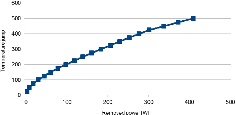
Retrieving the data for the nitrogen properties, and combining these with the assumed inlet temperature and the maximum allowable outlet temperature, the final combined equation
T c k h g Q p c
brings to about 340 W that can be removed by natural circulation of nitrogen without exceeding 820 °C as maximum temperature. A plot of the dependence of 𝛥T versus Q is shown in Figure 1.
Figure 1 –Plot of the correlation between residual power of a FA and outlet nitrogen temperature (the inlet one being 380 °C) under natural circulation.
It is to be noted, however, that at such temperatures the heat removal by irradiation plays a non-negligible role. From similar studies [4] its contribution can be assumed to increase the maximum residual power of a single FA to about 545 W (+60%).
4. Residual heat decay curve
Now that a target value is found for the maximum residual power allowing safe ex-vessel refueling (in the sense: making viable the option relying on natural circulation of the gas for the passive cooling of a FA stuck outside the primary pool), a study of the decay heat produced in a FA after irradiation is to be performed.
As a premise, it is worth resuming the interim in-vessel storage procedure in order to catch all the elements needed for the correct modeling and simulation of the phenomena.
The core is operated in a 5-batches refueling strategy that is: the FAs are apportioned in 5 groups so that, after each operation cycle, all the FAs belonging to one of the batches (changing in turn every cycle) are unloaded from the core, having achieved the design residence time, and substituted by fresh ones.
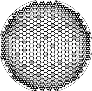
The spent elements are then moved towards the storage area aside the core (Figure 2), waiting the sufficient time to be moved outside of the primary system towards the storage pond of the plant.
Figure 2 – ALFRED core map: the interim in-vessel storage area is the outermost ring (darkest gray).
4.1. Reference decay curve for spent fuel elements
As previously mentioned, the unloaded FAs are parked in the in-vessel storage area until their residual power lowers enough to be cooled in gas, allowing refueling. However, they cannot be moved until the next, or one of the successive, planned outages for refueling. Now, being 5 both the years of overall in-pile residence time for the FAs, and the number of batches for the
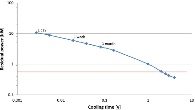
The starting point for the correct evaluation of the in-vessel storage option is, therefore, to evaluate the natural behavior of the residual heat in a FA after the five years of full-power irradiation in core. The results of the FISPACT code for this first case are shown in Figure 3.
Figure 3 – Time decay of the residual power of a FA after 5 years full-power irradiation in ALFRED. Looking for the intersection of this decay curve with the line quoting the maximum power that can be removed by natural circulation of nitrogen (previous Section), it turns out that a time between two and three years is required. For the considerations drawn in the opening of this Subsection, three years of in-vessel cooling are the minimum candidate to be considered for the further analyses.
4.2. Effect of neutron irradiation during interim storage
The previous analysis has to be corrected because of the neutron flux illuminating the spent FAs during their residence in the in-vessel interim storage area. This flux indeed generates locally new fissions, hence new, fresh fission products, which are to be accounted to more precisely evaluate the overall residual power produced by the fuel elements waiting for transfer to the plant storage pond.
A consideration is however due to this regard. The spent fuel elements in the parking area must be as much as possible decoupled from the fuel elements in core, not only to minimize the effects on the driver region, but also in order to not pose safety concerns. The decoupling is usually done by means of absorbers in the outermost positions of the shield surrounding the driver core, again in order to reduce their impact on the core performances.
To the aims of this work, and to the sake of the companion one [5], all this turns out to be a matter of tradeoff between not impairing core performances (weak absorbers) and minimizing the re-ignition of the spent FAs (strong absorbers).
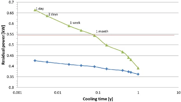
The effect of the further irradiation on a spent FA parked in the in-vessel storage area, can be well seen by the shift of the residual power right after reactor shutdown after the third cycle following the unloading of the FA (Figure 4): with respect to the original residual power after an equal cooling period (blue line taken from Figure 3), the new curve (green line) is shifted upwards, notably right after the new irradiation (+56% one day after shutdown) and then progressively reducing the difference with time (+8% after one year).
Figure 4 – Time decay of the residual power of a FA after 3 years of interim in-vessel storage (green line) compared with the corresponding curve of Figure 3 (blue line).
Since the target allowed power was already lowered well before reaching three years natural cooling, it can be seen that the time of outage needed after shutdown is approximately in the order of one month.
This result, retrieved for the average FA, means that the ones in the farter positions of the storage area from the core will be allowed to exit the system well before one month (between one and two weeks after shutdown); on the other hand, the FA that will have received the highest flux during interim storage will need almost two months to be cooled down below the threshold value of 545 W.
5. Discussion and conclusions
In order to provide a comprehensive understanding of the implications of in-vessel storage, some general considerations have to be put forward.
A general question is useful at this point to support driving the discussion: what is the acceptable time for an outage to wait the spent fuel elements to cool down before removal from the primary pool? For ALFRED, as a demonstrator reactor, although no economic performance is expected, the proof of a viable and economic solution for refueling might anyway be desirable. Moreover, there are other issues (notably safety-related) associated to the decision of the optimal in-vessel storage time that have to be taken into account.
leaving the spent FAs in the parking positions for 5 years instead of 3 permits to reach manageable residual powers already few days after shutdown, instead of about one month. But, on the other hand, of course a longer in-vessel storage implies a higher number of batches to be accommodated. And – since the performances of the shield protecting the inner vessel from core leakage cannot be lowered – to create new positions the inner vessel itself has to be enlarged. This has a direct impact on the overall plant dimensions, increasing costs and both static and dynamic loads. The latter implying a tougher seismic design, which once again impacts on costs.
Moreover, the more spent elements are placed in the parking area, the higher the self-sustaining effect due to the local increase of the reactivity. Which has a twofold impact:
the further increase of the new fission products generated during storage, hence of the residual power expected at outages, partially reducing the benefits of extending the storage period;
the increase and hardening of the neutron flux insisting on the inner vessel, potentially imposing the use of neutron-absorbing pads aside the inner vessel to protect the latter against irradiation damaging; for using the pads, once again the inner vessel has to be enlarged, and the cost of the plant increases.
For the envisaged refueling scheme (in-vessel storage area sized to accommodate 3 batches), the outer ring of dummy elements had to be replaced by absorbers in order to decouple the driver core from the parking area. In the investigated case, as a tradeoff solution, natural boron carbide was considered, having the non-negligible impact on core criticality of about 620 pcm. Increasing the number of spent elements to be hosted might require the use of enriched boron carbide, enhancing the anti-reactivity to be managed at core level.
All these considerations are to be added when evaluating the possibility of adopting the in-vessel storage strategy. It is opinion of the writers that referring to not less than three batches in the storage area, with all the implications discussed above, is increasing the complexity of an already complex procedure beyond the point where confidence of solving a challenge is questioned by the new drawbacks introduced. Beyond enough to let the Authors envisage different solutions to manage the refueling of spent fuel elements.
References
[1] A. U.S. Department Of Energy Nuclear Energy Research Advisory Committee and Generation IV International Forum. A Technology Roadmap for Generation IV Nuclear Energy Systems. Technical Report GIF(2002), http://www.gen-4.org/Technology/roadmap.htm.
[2] B. R. A. Forrest. The European Activation System: EASY – 2005. UKEA FUS 513; FISPACT -2005 User’s Manual, UKEA FUS 614.
[3] C. K. Mikityuk et al. Thermal-hydraulic assessment of the ALFRED core. LEADER Project, Deliverable TEC056, 2012.
[4] D. J. Janssens et al. Description, functional sizing and drawings of the main components of ALFRED. LEADER Project, Deliverable TEC057, 2013.
[5] E. F. Lodi et al. Characterization of the new ALFRED core configuration. Ricerca di Sistema Elettrico, Technical Report ADPFISS-LP2-085, 2015.