ADS-B signals reception: a Software Defined Radio
approach
Emilio G. Piracci, Gaspare Galati, Marco Pagnini
Tor Vergata UniversityElectronic Engineering Department Via del Politecnico, 1
00133, Rome, Italy
[email protected], [email protected] Abstract—In Air Traffic Control, ADS-B (Automatic
Dependent Surveillance - Broadcast) systems provide surveillance information as obtained by the cooperating airplanes. This usage of air-derived data and of a common link opens various issues: performance in dense traffic area, signals validation and security. A Software Defined Radio (SDR) permits the needed flexibility and modularity in order to easily develop prototypal devices for evaluation and test of novel enhancements of ADS-B receivers. In this frame, a multi-channel receiver for 1090 MHz ADS-B signals was implemented, using an array antenna, a specific designed analog front-end and a software defined receiver. The device is useful to test signal processing algorithms and to analyse the channel traffic. The receiver is also jointly used with another SDR device capable to generate 1090 MHz traffic. With this configuration it is possible to generate specific traffic scenarios characterized by interferences from multiple sources and/or by jammer. This paper deals with the hardware and set-up description, the presentation of the developed software receiver and its functions, and, finally, the results achieved using the system.
Keywords— ADS-B, 1090 MHz signals receiver, Software Define Radio
I. INTRODUCTION
ADS-B (Automatic Dependent Surveillance – Broadcast) systems provide air traffic informations for surveillance purposes [1] using the 1090 MHz mode S signals [2]. The airborne transponders with ADS-B capabilities transmit periodically several information about the flight status including: identity, 3D position (latitude, longitude and height), velocity vector. The data, that are obtained by on-board navigation equipment, are sent on a 1090 MHz carrier signal, in compliance with the mode S requirements [2] using an amplitude modulation: the signal is composed by a four pulses preamble followed by a data-block with a 1 Mbit/s data rate. Each bit is encoded with a pulse position modulation (PPM) dividing the 1 µs interval into two 0.5 µs chips: for bit ‘1’ the signal is present only in the first chip, and for bit ‘0’ the signal is present only in the second chip. Figure 1 shows the typical signal scheme. The airborne component of an ADS-B system transmits airplane position and height as derived from the on-board navigation equipment (typically
GPS). The repetition period of the data messages varies from 6 s (en-route area) to 0.5 s (approach and airport area).
t [μs ]
0 1 3.5 4.5 8
8 μs preamble 56/112 μs data block
= 1
= 0 PPM scheme
c1 c2 c1 c2
Fig. 1. Mode S signal scheme
ADS-B systems are characterized by an easy implementation and a lower cost as compared to surveillance radars. However, they are affected by problems related to security, system integrity, and system performance in high traffic density areas. A typical ADS-B ground station receiver (that usually is equipped with a non-directional antenna) is easily exposed to radio-frequency threats, and in high air traffic density, due to the random access to the channel, the probability of receiving overlapping signals is not negligible [13]. Possible solutions based on algorithmic method for signal separation are proposed in [9]-[11]. Moreover the ‘open’ mode S protocol does not guarantee security: actually low cost devices are available to receive the ADS-B signals and then to track the pertaining flights. It is also possible to generate false traffic (spoofing). The latest issue is addressed in [3] and [4] with a more general survey of security on airplanes and related elements, including ADS-B. Finally, an unavailability or damage of the on-board equipment implies the transmission of bad information for the pertaining flight that should be not detected by the receiver if not validation solution are adopted. There is a large literature about integrity monitoring, ADS-B signal validation, reception enhancements and related signal processing techniques. In [14] a solution for the integrity check is proposed combining multilaterations at the ground controller. Another solution for terminal area is the
use of secondary surveillance radar for verifying the position information [15].
Actually, activities on ADS-B and 1090 MHz signals related problems from intentional and un-wanted interferences are ongoing. The goal of this field of research is the implementation of signal processing algorithms and methods for 1090 MHz overlapping signals separation [18]. These methods are useful both to increase surveillance capacity and to detect a jammer. The algorithms act on the received signal upstream the messages decoding stage. In this context a 1090 MHz multichannel receiver was implemented (Transponder Data Recorder, TDR in the following) [5]. The TDR is designed to receive and record live signals from an array antenna, is useful for channel characteristics estimation, as well as to collect signals for trials and tests. Moreover, the algorithms are tested by a heavy garbling and jamming scenario, obtained by the joint use of the TDR and a SDR model USRP 2920 [6], used to generate RF traffic. Both the receiver and the transmitter are configured and managed via software developed in National Instruments (NI in the following) LabView and Matlab programming environment. This paper contains in section II the description of the hardware and the description of the set-up, in section III the presentation of the TDR and NI USRP software functionalities. The achieved results on channel traffic evaluation and the jammer simulation are presented in section IV, finally in section V contains the conclusions and perspectives.
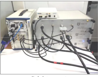
II. HARDWARE AND SET-UP DESCRIPTION The 1090 MHz multi-channel receiver is composed by the antenna, the analog section and the digital section. The antenna is an array of six patch elements placed on the Engineering Faculty roof; a detailed description is in [7]. The analog section is a dedicated front-end for RF signal reception and downconversion with five channels: four independent linear channels and one ‘logarithmic’ channel. The four linear channels are connected to the central elements of the array, they downconvert the signal to intermediate frequency (IF) at 21.5 MHz. The logarithmic channel is connected to a side element of the array. It is based on the Analog Device AD8313 [8] receiver, with a base-band output. The six-th element of the array is connected to a 50 Ohm dummy load. A detailed description of the TDR analogue section is in [5]. The digital section is based on a NI platform composed by the controller NI PXIe 8135, three acquisition cards NI PXIe 5122 and a FPGA card NI FlexRio PXIe7966. Each acquisition card NI PXIe 5122 has two input independent channels, and a sample rate up to 100 Msamples/s. These devices are controlled by software in National Instruments LabView programming environment. In the following paragraph the receiver software modules are described. The other SDR device used to generate 1090 MHz signals is the NI USRP 2920. It is possible to control with NI LabView both the analog and digital sections of the device, programmable as transmitter and/or receiver. USRP is equipped with two bi-directional (input/output) selectable channels. Figure 2 shows a photo of the system components: on the left the digital
section, on the right the TDR analog section, on the top the NI USRP device.
Fig. 2. System components
Depending on the application, various experimental set-ups have been implemented. For signal processing algorithms test, the four linear channels and the logarithmic channel outputs of the TDR are connected to the input channels of the digital section. The NI 5122 acquisition cards acquire the signals directly at IF, with a sampling frequency of 100 Msamples/s. This set-up permits also to test array signal processing algorithms. Another set-up has been implemented to generate a traffic scenario characterized by an high signals density or to simulate the presence of threats like jammer or spoofer. The USRP output is cable-connected to a RF combiner with an element of the receiver antenna. The output of the combiner is connected to a TDR input channel The USRP is properly programmed to generate 1090 MHz signals, like ADS-B messages or interferences (jamming, noise etc.). The resulting signal is used to test the effectiveness of interferences mitigation methods. Another antenna element is directly connected to the TDR, the acquired signals (with no interferences) is used for test and evaluation. Figure 3 shows the described set-up schemes.
(a) Trials with interferences/jammer
array coupler USRP TDR ch1 ch2 ch3 ch4 LOG NI NI5122 NI5122 NI5122 NI5122 FPGA user work-station
(b) signal processing trials
Fig. 3. Hardware set-up
III. RECEIVER/TRANSMITTER FUNCTIONALITIES AND SOFTWARE DEVELOPMENT
A. TDR SDR receiver for 1090 MHz signals
The software modules to control the NI hardware of the TDR digital section have been programmed in LabView. The software of the receiver is based on two operational levels. The high level is useful to set the recording session parameters. The user can choose which channels to acquire and which type of signal to detect and to process. In practice, it is possible to receive only Mode S, only Mode A/C or both, from any combination of the five receiving channels. Then it is possible to configure the time settings: the session should be time continuously or time defined, or stop after the receiving and decoding of a defined number of signals. The software permits to set the acquisition triggering mode: setting ‘software trigger’, the acquisition start with a logical state of the software (e.g. the software sets the trigger after the detection of a certain waveform); using ‘signal trigger’ the acquisition start when the signal exceed a user defined threshold and finally, with the ‘immediate mode’ the acquisition start without any external trigger. Other settings are related to memory recording. It can be chosen whether to record the decoded signals, choosing what type (Mode S, Mode A/C or both) and from which channels, otherwise it can be recorded only the timestamps associated to the decoding events. The last option is useful to evaluate the channel traffic, avoiding memory usage for signals recording. Finally, the relative parameters to the reception of ADS-B messages can be set. The user can enable this feature, obtaining the air-derived data from cooperating flights. The analysis of ADS-B signals is very useful to evaluate detection and decoding methods. In fact, the ADS-B message payload, in addition to the position data, contains the unique 24 bit ICAO Identifier of the airplane, that allows to perform error check on the decoded binary sequence. It permits to get statistics and quantitative assessments. Table 1 summarizes the configurable parameters and settings of the ‘high level’ human machine interface (H.M.I.).
TABLE I. TDR PARAMETERS SETTING
Parameter settings
Channel Any combination of the four linear and LOG channels Signals Mode S/Mode AC/DF 17: any combination Session
duration Time cont. / Time defined / # Decoded signals based Acquisition
start Software trigger / Immediate / Signal trigger Memory
recording Linear / LOG channels (any combination) / Type DF17
functionality Track flights / Discard
Prior to TDR usage, the receiver parameters are to be configured. The human-machine-interface (HMI) permits to configure different receiver and recording modes. The software to manage the above described parameters, operates on the digital section controller. Instead, the software for the ‘low level’ settings, useful to manage signal processing configuration operates directly on the acquisition cards NI 5122, and includes the FPGA module. The object oriented programming permits a user friendly H.M.I., as shown in figure 4 where the front-panel of the software is shown, also for the low level settings.
Fig. 4. Screen-shot of the TDR acquisition software (front-panel) The software section dedicated to the configuration of decoding and signal processing settings allows the user to define the decoding and confidence declaration methods. The detection of Mode S and conventional signals is implemented in compliance with the standards [1]-[2]. The user can choose different decoding and confidence evaluation methods: the enhanced methods in appendix I of [1] or the methods proposed in [16]. In this section the user can also set-up the sampling frequency of the A/D converters (from 10 Msamples/s to 100 Msamples/s), and can decide to enable additional signal processing algorithms to implement signal separation methods [9]-[10]-[11]. It is also possible to add
array TDR ch1 ch2 ch3 ch4 LOG NI NI5122 NI5122 NI5122 NI5122 FPGA user work-station
other signal processing functionalities by adding the related block in the receiver software scheme and properly “wiring” it into the receiver block diagram. Figure 5 shows a part of the related block diagram.
Fig. 5. Screen-shot of the TDR acquisition software (block-diagram) Once the additional signal-processing block is “wired” into the block diagram, with a control button on the front-panel (figure 4) it will be possible to enable/disable the related functionality. Actually, for the ongoing research activity a software module for single channel processing is implemented: the so-called PASA method [11] permits the detection and separation of overlapping signals.
B. NI USRP 2920 for 1090 MHz signals and jammer generation
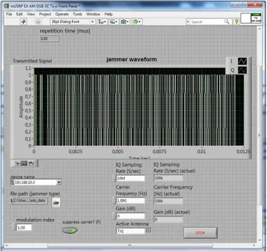
The 1090 MHz signals and interference (jammer) generation is managed by the USRP 2920. This device permits the transmission and/or reception in the 50-2200 MHz band, with a settable sampling frequency up to 25 Msamples/s. The analog and digital sections of NI USRP are software controlled in LabView. When used as transmitter, first a file containing the I and Q samples (the base band signal) is loaded and the modulation mode and type is defined (both analog and digital modulation modes are available). Then, the parameters of the signal to be transmitted are chosen, i.e. the I and Q sampling rate and the carrier frequency. Finally the output power can be set from -11 dBm to 20 dBm (EIRP). For SSR 1090 MHz signal generation, the base band samples file has been composed in Matlab, the I and Q sample rate has been set at 10 Msamples/s. It permits to obtain edge shape of the transmitted signal pulses in compliance with the timing requirements [1] and [2]. The implemented software permits to choose on the front-panel the signal waveform to be transmitted, the repetition period and the signal level. Figure 6 shows a screen-shot of the front-panel.
Fig. 6. Screen-shot of the USRP software (front-panel) IV. RESULTS
Using the described hardware and software it is possible to test detection mode S and ADS-B and signal processing algorithms. Moreover it is possible also to analyse the 1090 MHz channel characteristics in terms of traffic load, probability to receive interference (overlapping signals), signals carrier frequency and other. Finally, the developed system is useful to evaluate the consequences of intentional threats (jamming) on a typical ADS-B ground receiver and the effectiveness of mitigation methods. The following sub-sections contain the description and the first pertaining results about the activities on channel estimation and ADS-B vulnerability to jammer.
A. 1090 MHz channel traffic estimation
The estimation of the 1090 MHz channel traffic is useful to understand which problems can arise for an ADS-B receiver, and to define the most efficient solutions. For instance, the proposed methods [9]-[11] for the signals garbling problem have the better performance greater is the overlapping signals diversity (in terms of directions of arrival or carrier frequency). The recording sessions were performed during the week of 6-13February 2014, from 8.30 a.m. to 3.30 p.m.. Table 2 shows the traffic load and the interference rate related to the area around the TDR site (Tor Vergata University, South-East w.r.t. the centre of Rome). Less than 6 % of the received signals are affected by some garbling problem. Under this condition the interference are still acceptable and this low interference rate is due to the limited number (not more than 22) of Mode S transponder equipped aircraft under visibility. A ground receiver close to a big airport and an airway area should be affected by interferences, as stated in [17]. The data shows also a substantial actual usage of the conventional Mode A/C of the SSR. The area under TDR visibility is
‘interrogated’ by two SSR radar at least (an approach radar at Fiumicino airport and a near-by en-route station), and maybe more depending by the operational status of the radar sites network. The acquisition time (5 sec.), considering the typical scan time of a SSR (5-12 sec.), was decided in order that all the airplanes in visibility were interrogated by an SSR.
TABLE II. 1090MHZ TRAFFIC CHANNEL DATA
Acquisition time 9.30 a.m. 12 a.m. 1 p.m. 3.30 p.m.
Recording time 5 sec 5 sec 5 sec 5 sec
% of conventional signals 79 % 82 % 78 % 84 % % of Mode S signals 21 % 18 % 22 % 16 % % of garbling signals 4 % 4 % 6 % 3 % n. of Mode S transponders 14 10 22 14
Based on received signals, an analysis on the carrier frequency of the received signals was conducted. The results obtained shows a not-negligible frequency diversity between the different transponder. As shown in figure 7 the airborne transponders carrier frequencies (nominally at 1090 MHz) are distributed from 1089 MHz to 1091 MHz, with a standard deviation of 260 KHz (data obtained by the analysis of signals from 177 airplanes). This result is of interest considering the need of frequency diversity for the feasibility of PASA algorithm [13] to separate overlapping signals.
Fig. 7. Mode S signals frequencies distribution (UTV acquisition)
B. ADS-B vulnerability to jammer
In order to assess the effect of a jammer signal on an ADS-B receiver, as explained in section III.B, an external signal from
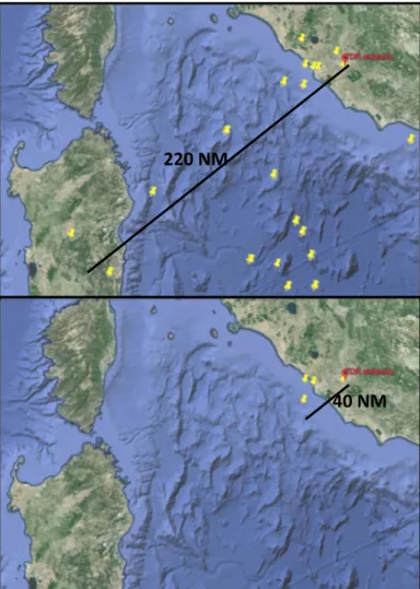
the NI USRP has been coupled to the antenna signal up-stream the input of the TDR. Before the antenna coupling, the NI USRP signal is 90 dB attenuated. Then, varying the output power from 0 dBm to 16 dBm, is equivalent to varying the jammer-TDR range from 7 km to 1 km. Another antenna element, jamming free, is directly fed into TDR. It is used to compare the decoding of the jammed channel. Three types of jamming waveform was elaborated: a) Mode S pulses train; b) Mode S preambles train; c) fake ADS-B signal train. The TDR was set to detect and decode Mode S signals in compliance with standard method as in [1]. As the jammer waveform are in compliance with SSR requirements [2], they are processed by the receiver, then the effects is a saturation of the computational capabilities. Moreover, since a signal to be detected and decoded must be 3 dB or stronger than an interference [1], the consequence is a reduction of the receiver range. Figure 8 shows the comparison of ADS-B flight tracks between free and jammed channel. The USRP output power was set at 7 dBm EIRP (equivalent to jammer at 3 km to the TDR antenna), and the range decreases from 220 NM to 40 NM.
Fig. 8. Comparison of the ADS-B plot between free and jammed channel The comparative analysis between free and jammed channels decoding, reveals that also nearest signals could be affected by
220 NM
the interferences. As shown in figure 9, from a target at 25 NM from the TDR, instead of 12 ADS-B messages, the receiver was able to detect and decode only 3 messages. The consequence should be a time discontinuous surveillance of target, not in compliance with the update interval requirements.
Fig. 9. Comparison of a ADS-B track between free and jammed channel V. CONCLUSIONS AND FUTURE WORK A SDR tool for the TDR, a multi channel 1090 MHz signal receiver, has been designed and implemented. The system allows us to receive and record avionic transponder signals, emitted as replies to the secondary surveillance radar and the ADS-B signals spontaneously emitted. The flexibility given by the SDR concept, permits an easy implementation and interexchange of additional processing modules. Then the TDR is a very useful system to analyse the traffic characteristics of the 1090 MHz channel, and to test new signal processing methods, array processing algorithms and enhanced decoding procedures. In this context a NI USRP permits to generate any traffic scenario, that can be coupled with the antenna signal at RF. The joint use of TDR and NI USRP permits to evaluate the ADS-B receiver performance in high FRUIT rate environment, and permits to compare the proposed decoding methods with the standard methods.
Ongoing research activities are related to the study and analysis of risk from RF threats (jammer and spoofer) for ADS-B ground systems, and to the solutions for these problems.
REFERENCES
[1] RTCA DO-260A: ‘MOPS for 1090 MHz ES ADS-B and TIS-B’, 2003. [2] ICAO: ‘Annex 10 to the convention on international civil aviation,
Aeronautical Telecommunications, Vol. IV Surveillance Radar and Collision Avoidance systems’, 2002
[3] Costin, A., Francillon, A.: ‘Ghost in the Air(Traffic): On insecurity of ADS-B protocol and practical attacks on ADS-B devices’, Black Hat USA 2012, available on EURECOM web site at https://www.eurecom.fr/fr/publication/3788/download/rs-publi-3788.pdf [4] Sampigethaya, K., Poovendran, R., Bushnell, L.: ‘Secure operation,
control, and maintenance of future e-Enabled airplanes’, Proceedings of IEEE, Vol. 96 n. 12 2008, pp. 1992-2007
[5] Galati, G., Leonardi, M., Petrochilos, N., Piracci, E.G., Samanta, S.: ‘Trasponder Data Recorder: final implementation and first results’ IEEE Aerospace and Electronic Systems Magazine, Vol. 29, I. 2, pp. 6-13. [6] NI website: USRP datasheet
http://sine.ni.com/ds/app/doc/p/id/ds-355/lang/it
[7] G. Amendola, S. Costanzo, V. Martire and G. Di Massa, “A broadband microstrip antenna for SAR applications,” in Proc. of 1999 IEEE AP-S Int. Symposium, 1999, Orlando (Florida)
[8] Analog Device AD8313 website datasheet: http://www.analog.com/static/imported-files/data_sheets/AD8313.pdf
[9] Petrochilos, N., Galati, G., Piracci, E.G.: ‘Separation of SSR signals by array processing in multilateration systems’, IEEE Transactions on Aerospace and Electronic Systems, 2009, Vol. 45, No. 3, pp. 965-982 [10] Piracci, E.G., Petrochilos, N., Galati, G.: ‘Mixed SSR sources exploiting
sparsity: a geometrical approach’, Proc. European Microwave Conference, 6th Radar Conference EuRad, Rome, Italy, September-October 2009, pp. 85-88
[11] Piracci, E.G., Petrochilos, N., Galati, G.: ‘Single antenna projection algorithm for Mode S based airport traffic surveillance’, Proc. European Microwave Week, 4th Radar Conference EuRad 2007, Munich, Germany, October 2007
[12] Piracci, E.G., Leonardi, M., Galati, G.: ‘ADS-B vulnerability to low cost jammer: risks assessment and possible solutions’, accepted to ESAV 2014, on January 2014
[13] Piracci, E.G, Galati, G., Petrochilos, N., Fiori, F.: ‘1090 MHz channel capacity improvement in the air traffic control context”, International Journal of Microwave and Wireless Technologies, 2009, 1 (3), pp. 193-199
[14] Sharples, M. Hutchinson, H., Carpenter, K., Browen, D.: “Integrity and security of ADS-B”, in Proc. SurTech, 2004.
[15] Krozel, J., Andrisani, I.: “Independent ADS-B verification and validation” in Proc. AIAA 5th Aviation, Technol., Integr., Oper. Conf
(ATIO), 2005, pp. 1-11
[16] Galati, G., Gasbarra, M., Piracci, E.G.: “Decoding techniques for SSR Mode S signals in high traffic environment”, in Proc. of European Microwave Week EuRad 2005, Paris, France, October 2005
[17] EUROCONTROL, ‘1090 MHz Capacity study – final report, CASCADE Programme’, edition number 2.6, June 2006.
[18] Petrochilos, N., Galati, G., Piracci, E.G.: “Array processing of SSR signals in the multilateration context, a decade survey”, in proc. Of ESAV 2008, Italy, Rome, September 2008, pp. 60-64