Vol.8 (2018) No. 1
ISSN: 2088-5334
A Model of Control Valve for Wagons Equipped by k-Blocks
G. Arcidiacono
*, L. Cantone
#* Dept. of Innovation and Information Engineering, Marconi University, Via Plinio 44, Rome, 00193, Italy E-mail: [email protected]
#
Dept. of Engineering for Enterprise “Mario Lucertini”, University of Rome “Tor Vergata”, Via del Politecnico 1, Rome, 00133, Italy E-mail: [email protected]
Abstract— Paper illustrates the key features of the control valve model of TrainDy, renewed to be compliant with wagons that equip
composite brake blocks type k in their braking systems. TrainDy is an international software owned by UIC (The International Union of Railways) and used by major Railway Undertakings in Europe to perform computations of Longitudinal Train Dynamics. Composite brake blocks type k equips new or revamped freight trains in Europe and are used to reduce train noise caused by particles of friction material between wheel and rail. This topic is particularly relevant since a relevant part of freight traffic in Europe is performed during night and many railway lines are close to highly populated areas. Paper shows the validation of this new model against experimental test campaigns performed at bench and in real field and made available for the revision process of UIC CODE 421 for freight train interoperability.
Keywords
—
Freight trains; composite brake blocks; k-Blocks; Control Valve; UIC CODE 421, TrainDy, Longitudinal TrainDynamics.
I. INTRODUCTION
European freight trains, differently from passenger trains, mainly employs brake blocks in their braking devices. Friction material of brake blocks is mainly cast iron P10 (P10) and it equips more than the 75 % of European freight wagons. Experimental tests carried out by UIC (The International Union of Railways) have proved that one of the main reasons for freight trains noise is caused by the cast iron particles, which keep attached to wheels after a braking and determine noise during the rolling of wheels on rail. Since a relevant part of railway freight traffic occurs during night and many railway lines are close to highly populated areas, noise reduction has become a relevant issue. In order to overcome this problem, since July 2006, all new or retrofitted wagons have to be conform to regulation [1].
According to some studies [2], by using composite brake blocks (CBB), it is possible to reduce emitted noise at 100 km/h up to 10/15 dB, with respect to P10 brake blocks, because CBB keep the running surface of wheels smooth, reducing wheel/rail contact noise. However, train noise reduction is appreciable if at least 75%-80% of trainset wagons are equipped by CBB. Since introduction of CBB is considered the preferred option to achieve a substantial noise reduction, according to the prescriptions of UIC CODE 541-3 [541-3], main European Manufacturers of CBB friction
material have developed two types of shoes. First type is labelled as “type k” (or k-blocks) and second type is labelled as “type LL” (or LL-Blocks); these types of shoes have values of friction coefficient higher than P10 and similar to P10, respectively. Because of its higher friction coefficient, employment of CBB type k requires a substantial renewal of wagon braking system: for example, brake cylinder is usually replaced with one of smaller cross section, control valve (or distributor) is redesigned, brake leverages are changed and so on. Moreover, friction coefficient variability with speed and normal force (between wheel and shoes) is lower than P10 and this guarantees better performances in terms of Longitudinal Train Dynamics (LTD).
LTD deals with the study of relative motion of adjacent railway vehicles running in track direction; LTD is a key factor in determining safety of freight trainsets: in fact, high in-train compressive forces can determine train derailment [4]. High in-train tensile forces are also dangerous, since they can disrupt trains (because of draw gears failure), causing a freight traffic inefficiency. LTD studies are carried on not only by Research Centres and Universities but also by Railway Undertakings, in order to develop longer and heavier freight trains. Reference [5] provides an excellent review of this matter and in [6] there is a benchmark of several LTD simulators coming from all over the world. Of course, such studies require a statistic approach [7], as
requested by UIC CODE 421 [8] for freight trains interoperability and, among the papers in literature that cover this topic, we can mention here [9] and [10].
In 2009, UIC has created the TrainDy Special Group, formed by the major Railway Undertakings and brake Industries of Europe, with participation of the University of Rome Tor Vergata (URTV), to enhance the TrainDy software, originally developed by URTV validated against Trenitalia data in [11]-[12] and internationally in [13]. This software is currently subjected to upgrade of some of its modules, in view of a revision process of UIC CODE 421, needed also according to [14].
As mentioned before, in order to model, in LTD simulations with TrainDy, wagons equipped by CBB type k, it is necessary to renew its model of Control Valve and its friction material module. This paper focuses on the first topic whereas the other is still under development and testing against experimental data, also as a result of approaches that the authors have developed in other works [15].
II. MATERIAL AND METHOD
A. Control Valve Model
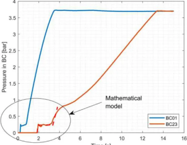
In UIC braking scheme, control valve (or distributor) is the device that transforms the air pressure drop in brake pipe (BP) into an air pressure increase in brake cylinder (BC); at this aim, it spills the pressurized air from the auxiliary reservoir (AR). This device has to be compliant with UIC CODE 540 O [16]. Figure 1 shows the time evolution of air pressure in two brake cylinders of a 600 m train.
Fig. 1 Filling of first and last brake cylinder of a 600 m train Following the time evolution of air pressure in those two brake cylinders (the first is placed at the beginning and the second at the end of the train), it is possible to split the brake cylinder filling into four phases (see also [17]):
1) Application stroke: It is the first phase of brake cylinder
filling when pressure rises in a short time because the hysteresis and the counteracting forces are overcame. After initial “spike”, air pressure is maintained constant for a certain time or until the air pressure, in brake pipe, is above a certain value.
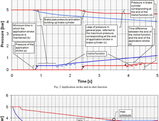
2) In-shot function: After application stroke, air pressure
in brake cylinder rises according to a linear function. At this end, it is enough to specify the duration and the final pressure reached at the end of in-shot function.
3) Filling, according limiting curve or brake pipe pressure drop: In-shot function is followed by air
pressure increment in brake cylinder according to “limiting curve” or “transfer function”. Usually, wagons close to the source of air pressure drop (i.e. close to the traction unit) follow the “limiting curve profile”, whereas wagons far from the source of air pressure drop follow the “transfer function”.
4) Plateau: When air pressure reaches the maximum
value, it remains constant until air pressure in brake pipe does not increase because of a brake release. Figure 2 summarizes the first two phases, whereas Figure 3 synthetizes the last two phases, which refer to a train in braking position G (“Goods”). Curves, in both figures, refer to brake cylinders of first and last wagon of the train.
As shown by Figure 3, limiting curve is defined by two values of time: the first is the time, after brake cylinder initial filling (i.e. start of application stroke phase), needed to reach the 95% of maximum pressure (t95); the second is the time to reach the 100% of maximum pressure (t100). By these times and by the final point of in-shot function, a parabolic curve is computed with null slope at t100. Figure 4 shows a typical transfer function of a control valve for braking and brake realise manoeuvre. Transfer function is a design characteristic of control valve and it provides, in a quasi-static way, the pressure in brake cylinder knowing the local pressure in brake pipe. In reality, as the experimental results of this paper clearly show, air pressure in brake cylinder does not follow exactly the behaviour imposed by transfer function, but it is close to it. During a braking, control valve numerical model in TrainDy imposes to the time value of air pressure in brake cylinder to be equal to the minimum value between the limiting curve and transfer function.
Comparing the real behaviour showed in Figure 1 with the curves modelled in Figure 2 and Figure 3, it is clear that TrainDy model of control valve approximates the filling of brake cylinder, even if it is capable to replicate its main features: air pressure oscillation, during the application stroke or in-shot functions are not permitted, as they happen in reality. A more accurate modelling of control valve requires a higher computational effort, because of the complexity of fluid-dynamic problem. Anyway, practical effect of this approximation is negligible, as reported in [11], and one of the aims in designing the models of TrainDy is to find a trade-off among accuracy and computational efficiency. Therefore, first two phases are based on a mathematical (arithmetic) model; the other two are based on curves that can be derived by the design of control valve.
Maximum value of pressure in brake cylinder changes according to wagon payload; there are several design ways to achieve this task, but the result is the same and it can be split into:
a) Two stages of pressure: typical of “old” empty-load devices, where according to payload value, the wagon is set in “empty” or “loaded” (or “laden”) condition. b) Infinite stages of pressure: typical of “recent” auto-
continuous devices, where according to payload value, the wagon braking force changes continuously from low values (“empty” condition) to high values (“loaded” condition).
Fig. 4 Control valve transfer function for braking and releasing manoeuvre
In order to simulate the specific behaviours of control valves used for wagons equipped with CBB shoes type k, the previous (standard) model of TrainDy has been generalized, in order to meet one of the aims of UIC CODE 421, i.e. to create models able to increase the types of wagons manageable by TrainDy. Differently from previous model of control valve, the new one is capable to manage different values of pressure in brake cylinder, according to gross mass (i.e. payload plus tare) of the wagon, in order to simulate:
a) Application stroke. b) In-shot function. Releasing/braking transfer function
0.00 0.50 1.00 1.50 2.00 2.50 3.00 3.50 4.00 2.60 3.00 3.40 3.80 4.20 4.60 5.00 pBP [bar] p B C [ b a r] Braking Releasing
Fig. 2 Application stroke and in-shot function
0 1 2 3 4 5 6 0 5 10 15 20 25 30 35 40 Time [s] P re s s u re [ ba r] End of the inshot function 95% max pressure
For intermediate values of gross mass, linear interpolation of input data is used. Moreover, the time for in-shot function in braking position G is different from the counterpart in P (“Passenger”). The ratio of such times is the same of the ratio of the time to reach maximum pressure in brake cylinder in the two braking positions (usually this value is 5-6). Furthermore, since, in some cases of empty conditions, the target pressure is lower than the application stroke or in shot function pressure, pressure in brake cylinder follows the value of the pressure in brake pipe according to the transfer function. In standard TrainDy model, the pressure in brake cylinder cannot decrease during a braking application after in shot function and this result in pressure value that does not oscillates. In order to match experimental curves, this behaviour needs to be changed. Finally, since some devices exhibit peaks of air pressure in brake cylinders, control valve model has been generalized in order to manage a peak of air pressure, during the application stroke phase. All these models are validated in next section.
III.RESULTS AND DISCUSSION
A. Model Validation vs. Experimental Tests
During the development of the new control valve model described before, some representative experimental tests have been taken into account. Experimental tests can be divided in two types:
a) Bench tests: three devices tested, performing several types of braking applications.
b) Field tests: one device tested, in two nominally equal braking applications.
First control valve tested at bench changes maximum pressure in brake cylinder according to wagon gross mass. Three loading conditions have been tested:
a) Tare (Empty), tests from A19 to A24; b) Intermediate payload, tests from A25 to A30; c) Full load, tests from A31 to A36.
For each loading condition, there are 6 tests since each loading condition is further divided in three types of braking:
a)Emergency braking (target pressure in brake pipe equal to 0bar);
b)Service braking (target pressure in brake pipe equal to 3.5bar);
c)First time braking (target pressure in brake pipe equal to 4.5bar).
Finally, each braking, has been performed in braking position P and G, characterized by different times to reach the maximum pressure in brake cylinder. The overall number of tests for this device is equal to 18.
Since it is not possible to report all tests, for sake of conciseness, we report the following results for both braking conditions in:
Emergency braking in tare conditions, in Figure 5;
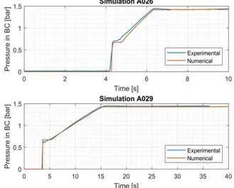
Service braking in intermediate conditions, in Figure 6;
First time braking in full load conditions, in Figure 7. It is worthwhile to point out that the results have been obtained with the same input settings, without any further adjustment. In all circumstances, the agreement among the experimental tests and the numerical counterparts is satisfying, since the absolute error is always less than 0.2 bar and relative error is always less than 5%: such values have
been considered acceptable during TrainDy certification [13]. It should be considered that the maximum air pressure in brake cylinder is never equal to 3.8 bar (typical of UIC
Fig. 5 Time evolution for air pressure in brake cylinder for an emergency braking performed in empty conditions: braking position P is above, and G is below
Fig. 6 Time evolution for air pressure in brake cylinder for a service braking performed in intermediate load conditions: braking position P is above, and G is below
Fig. 7 Time evolution for air pressure in brake cylinder for a first-time braking performed in full load conditions: braking position P is above, and G is below
brake cylinders), for the reported tests, since emergency braking has been performed in tare conditions, where the maximum air pressure is below 3.8 bar. For the other two braking conditions (service and first-time braking), the maximum pressure in brake cylinder is below 3.8 bar, because the air pressure drop in brake pipe is relatively “small”, i.e. not able to allow the control valve to fill the brake cylinder up to 3.8 bar.
Similar results, with the same level of agreement, can be found for the other two devices tested at bench:
a) An empty-load control valve with two levels of maximum pressure in brake cylinder: one for empty condition and another for load condition. For this device, the same three types of manoeuvre are tested: emergency, service and first-time braking. Control valve performances in braking position P and G are tested. Twelve tests have been performed.
b) An empty-load control valve with only one level of maximum pressure in brake cylinder: variation of braking force is obtained mechanically, by changing the rigging ratio. This device has been tested for the same braking manoeuvres both in P and in G. Six tests have been performed.
Hereby, each device, is characterized by a specific set of parameters, in order to build a “device library”, for TrainDy.
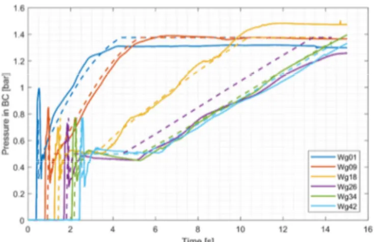
The last validation test refers to a field test performed with a different family of control valve and it is reported in Figure 8, where experimental measurements are reported in solid line and numerical results are reported in dashed lines. The same colours are used for the same wagons. Performed manoeuvre is an emergency braking in empty conditions and in braking position P; train length and mass are approximatively 530 m and 1000 ton, respectively. There are two field tests, the results of the two are similar since they perform the same manoeuvre and here only one of them is reported, for sake of conciseness. For this type of control valve, during the application stroke phase, the air pressure can be very high for a short time. This behaviour has been numerically modelled by a parabolic curve.
Fig. 8 Time evolution for air pressure in brake cylinder for an emergency braking performed in empty conditions: real field test
The agreement is still satisfactory but is lower than in the previous case, since brake cylinders filling in real field could differ from target behaviour and this is common for real field devices and it is not a particularity of this test. Solid lines of Figure 8 show that maximum experimental pressures are all
different; on the contrary, they should be the same. Experimental rising of air pressure is somehow oscillating, differently from numerical results, because numerical model does not take into account for all moving parts and contact hysteresis. During application stroke, experimental spikes are all different, whereas the numerical ones are all set at the same value, as it should theoretically happen. In spite of such differences, the developed numerical model of control valve is able to handle also this type of device, since it is able to catch its most relevant features.
IV.CONCLUSIONS
Paper reviews the numerical model of control valve used in TrainDy software, certified by UIC against more than experimental tests. It also introduces a generalization of this model in order to simulate control valves. typically used on wagons equipped with composite brake block (CBB) shoes type k. Control valve model is based on some equivalent (or calibrating) parameters that need to be set, by comparison against experimental tests. Procedure is not complex, and it can be automated, too. Almost forty experimental tests (bench and field test) have proved the accuracy of the new developed model and paper shows the matching experimental vs numerical for some of them, including one real field test. Once parameters identification is performed, the specific device is “mapped” and it can be used in TrainDy software for computation of Longitudinal Train Dynamics (LTD). This work belongs to the stream of revision process of UIC CODE 421 for the international freight train traffic. By this model, it is possible to simulate wagons equipped with CBB shoes type k, with a level of accuracy better than before, because of the model generalizations implemented. By this type of model, a better accuracy for computed in-train forces is expected for wagons equipped with CBB type k.
REFERENCES
[1] Commission Regulation (EU) No 1304/2014 of 26 November 2014
on the technical specification for interoperability relating to the subsystem ‘rolling stock — noise’ amending Decision 2008/232/EC and repealing Decision 2011/229/EU.
[2] A. Bracciali, M. Pippert, S. Cervello, Railway noise: the contribution
of wheels, Brescia, Lucchini RS 2009.
[3] UIC CODE 541-4, Brakes - Brakes with composite brake blocks –
General conditions for certification of composite brake blocks, 4th edition, December 2010.
[4] European Institute for Railway Research, ERRI B177.5/RP1 Etude
del probabilities de derailment de trains de marchandises sous l’influence d’efforts longitudinaux de compression eleves, 1999.
[5] C. Cole, M. Spiryagin, Q. Wu, et al., “Modelling, simulation and applications of longitudinal train dynamics”, Vehicle System
Dynamics, vol. 55, pp. 1498-1571, 2017.
[6] Q. Wu, M. Spiryagin, C. Cole et al., “International benchmarking of longitudinal train dynamics simulators: results”, Vehicle System
Dynamics, vol. 56, pp. 345-365, 2018.
[7] G. Arcidiacono, C. Calabrese, K. Yang, Leading Processes to Lead
Companies: Lean Six Sigma: Kaizen Leader & Green Belt Handbook. Milan, Italy: Springer Verlag, 2012.
[8] UIC 421 OR, Rules of the consist and braking of international freight
trains, 9th edition, January 2012.
[9] M. Ansari, E. Esmailzadeh, and D. Younesian, “Longitudinal dynamics of freight trains”, In. J Heavy Veh Syst, vol. 16, pp. 102– 131, 2009.
[10] G. Arcidiacono, R. Berni, L. Cantone, P. Placidoli, “Kriging models for payload distribution optimisation of freight trains”, International
[11] L. Cantone, A. Palazzolo, “Pneumatic validation of traindy with Trenitalia experimental data [Validazione pneumatica di TrainDy con dati sperimentali Trenitalia]”, Ingegneria Ferroviaria, Vol. 63, pp. 409-418, May 2008.
[12] L. Cantone, D. Negretti, A. Palazzolo, R. Karbstein, “Dynamic validation of the new International Union of Railways (UIC) simulator for the longitudinal dynamics of trains, namely, TrainDy with experimental data from Deutsche Bahn (db) and Trenitalia [Validazione dinamica di TrainDy con dati sperimentali DB e Trenitalia]”, Ingegneria Ferroviaria, vol. 64, pp. 165-172, February 2009.
[13] L. Cantone, “TrainDy: the new Union Internationale Des Chemins de Fer software for freight train interoperability”, Proc. IMechE, Part F:
J. Rail and Rapid Transit, vol. 225, pp. 57-70, 2011.
[14] L. Cantone, A. Ottati, “Methodologies for the hauled mass increase of freight trains in accordance with Fiche UIC 421 [Metodologie per l'incremento della massa rimorchiata dei treni merci in conformité alla Fiche UIC 421]”, Ingegneria Ferroviaria, vol. 70, pp. 109-128, February 2015.
[15] A. Giorgetti, C. Cavallini, A. Ciappi, G. Arcidiacono, P. Citti, “A holistic model for the proactive reduction of non-conformities within new industrial technologies”, International Journal of Mechanical
Engineering and Robotics Research, vol. 6(4), pp. 313-317, 2017.
[16] UIC CODE 540 O, Brakes – Air brakes for freight trains and
passenger trains, 5th edition, November 2006.
[17] L. Cantone, E. Crescentini, R. Verzicco, V. Vullo, “A numerical model for the analysis of unsteady train braking and releasing manoeuvres”, Proc. IMechE, Part F: J. Rail and Rapid Transit, vol. 223, pp. 305-317, 2009.